Article

Effect of Geometrical Factors on Torsion in Cold Roll Forming of the Lower Side Beam of a Car

1
School of Mechanical Engineering, University of Science and Technology Beijing, Beijing 100083, China
2
Jiangsu Durable Machinery Co., Yangzhou 225000, China
*
Author to whom correspondence should be addressed.
Appl. Sci. 2021, 11(17), 7852; https://doi.org/10.3390/app11177852
Submission received: 5 August 2021 / Revised: 20 August 2021 / Accepted: 24 August 2021 / Published: 26 August 2021
(This article belongs to the Section Transportation and Future Mobility)

Abstract

:
Cold roll forming is a continuous metal forming process used to produce a large variety of profiles. A significant product of cold roll forming is asymmetric profiles, whose application is expanding in the construction of cars, houses, bridges, etc. Torsion is one of the common defects in the cold roll forming process of asymmetric section steel and sometimes seriously affects cold roll forming products. With the development of the economy and technology, many asymmetric cold roll-formed parts are being gradually applied to automobiles. Three-dimensional finite element analysis models of 12 stands with 700L sheet material were carried out using the professional COPRA RF and MSC MARC software, taking the lower beam of an automobile as the research object. Five geometric factors of the lower side beam were researched, and the influence rules of different geometric elements on the forming torsion were analyzed. We found that with the increase of web width, flange width, and vertical edge height and the decrease of the corner radius and strip thickness, the torsion defects of cold roll forming were improved to different degrees. The results also showed that the width of the flange has the most significant effect on torsion.

1. Introduction

Cold bending forming is widely used in various fields due to its unique high efficiency. However, the technology has not been fully mastered, and there are many unnecessary defects in production, such as torsion. Torsion is a common defect in cold forming. In particular, in the creation of products with asymmetrical cross-sections, it is easy to produce torsion defects, causing high levels of resource waste in production. Therefore, the research on torsion has extraordinary guiding significance for cold forming. In cold forming production, the use of finite element simulation is essential [1] because the inefficient trial-and-error method is often used to obtain the process rules. These process rules mainly include whether the deformation method and deformation speed of the plate and strip are reasonable.
In the process of cold roll forming, an edge will produce longitudinal extension, resulting in residual longitudinal strain, bending, torsion, and other defects when the material moves longitudinally in the roll. The greater the residual strain, the higher the defect rate will be [2]. Some researchers have already investigated the torsion defect in the cold roll forming process. Wan-Gi Cha [3] et al. found that the difference of longitudinal strain at the webs and the vertical edge of U-shaped steel had an essential effect on torsion by studying the bending and torsion defects in the cold forming of asymmetric U-shaped high-strength steel. They proposed the application of pressure to the web to improve the torsion. Yaser Tajik [4] et al. also studied the torsion defects of asymmetric U-shaped steel. They found that the long side and the short side did not contact the roller successively in the forming process, leading to different applying forces in the direction of thickness, resulting in torsion. They proposed changing the roll’s shape to solve the torsion problem and found that the simultaneous change of longitudinal strain at the edge could effectively reduce the torsion. Behrooz Shirani Bidabadi [5] et al. studied the influence of geometrical factors on the torque required to form grooved steel and found that the thickness had the most significant effect on the forming torque. The torque was closely related to the longitudinal strain of the edge but not to the transverse strain. Cristopher D. Moen et al. [6], considering the factors such as the crimping and uncoiling of the cold-formed strip, conducted a prediction study on the residual stresses of cold-formed steel members, and the residual stresses and strains showed a nonlinear increase trend with the increase of strip thickness. John Paralikas et al. [7] studied the influence of process parameters on the cold-forming quality of grooved steel, reduced the longitudinal strain at the edge, and weakened the redundant deformation by optimizing process parameters. Davoodi et al. [8] studied the effects of yield strength, strip thickness, angular increment, flange width, and other factors on the required torque and vertical component force in cold forming. They found that decreasing the yield strength, strip thickness, and angular increment could reduce the sheer component force and required torque. Reducing the strip width could reduce the vertical component force and increase the total required torque. Paralikas et al. [9] analyzed and studied the factors influencing the energy consumption of cold forming and found that the angle increment, rack spacing, and forming speed significantly influenced energy consumption. Lindgren [10] studied the relationship between U-shaped steel edge longitudinal peak strain and deformation length and material yield strength. Safari and Moslemi Naeini [11] studied the influence of forming parameters on the longitudinal strain and bending of edges. They found that the longitudinal bending increased with the increase of the angle. The peak of longitudinal strain at the border increased with the increase of strip thickness and angular increments. However, it decreased with the increase in the random frame spacing, web width, and flange width, independent of the friction coefficient and forming speed.
At present, the research on torsion defects has mostly focused on a specific section, such as the U-shaped section. However, the cross-sections in actual production are usually more complex, and there are many factors affecting torsion. In this paper, based on the previous research [12], research on single flanges is added to bring the study closer to the actual production. In this paper, five geometric shape factors were studied, and three molding schemes were designed for each element. Through simulation results, we found that with the increase of the web width, flange width, and vertical edge height and the decrease of the corner radius and strip thickness, the torsion defects of cold roll forming were improved to different degrees. The results also showed that the width of the flange has the most significant effect on torsion. This work provides theoretical guidance for the subsequent production of section steel.

2. Materials and Methods

2.1. Material Property

2.1.1. Metallographic Structure and Chemical Composition

Automotive lower beams use high-strength steel 700L; the metallographic structure of this material is mostly fine-grain ferrite and sorbate, with a small amount of pearlite and a bainite structure. The material was observed with an electron microscope, and the internal microscopic diagram is shown in Figure 1. The structures formed by pearlite and ferrite can be clearly seen at 50 μm, and the structures formed by bainite and ferrite can be clearly seen at 20 μm. The way the two tissues are distinguished is that the dislocation density of bainitic ferrite is significantly higher than that of pearlite ferrite. It can be seen that the tissues of each part are relatively uniform. This material is mostly used in construction machinery, automobile production, and other industries. This material has good plasticity, toughness, weldability, and excellent cold bending performance [13] (see Table 1 for the chemical composition of 700L material).

2.1.2. Mechanical Properties

The lower side beam of an automobile is formed by the cold roll forming of the strip. It is necessary to understand the material’s mechanical properties accurately if we want to make an in-depth analysis of the cold roll forming process. In this paper, the detailed mechanical properties of the material were obtained through the tensile test. Tensile samples were plate-type specimens. According to the GB/T 228.1-2010 tensile test method standard, tensile samples were made by transverse rolling and longitudinal rolling, and the size of the test pieces is shown in Figure 2. The tensile test was carried out on a Yangzhou Xinhong XDL-100 KN electronic universal testing machine, and the test data were taken as the average value of three times. Test data are shown in Table 2.

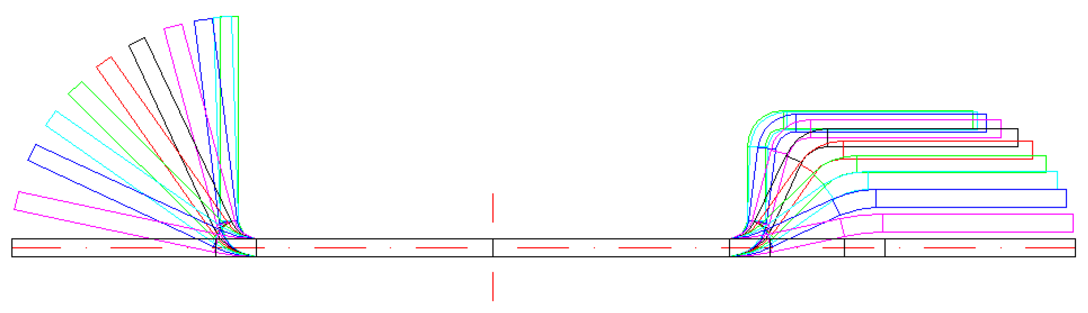
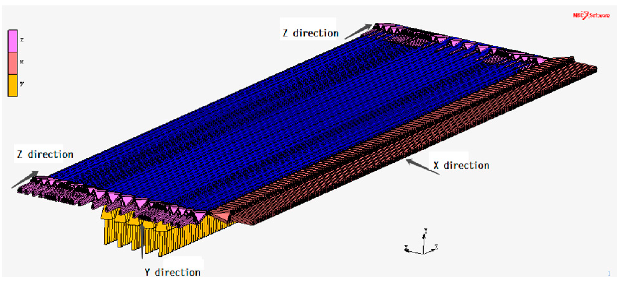
2.2. Establish the Simulation Model

The lower beam of the vehicle studied in this paper was asymmetric section steel, as shown in Figure 3. The thickness H and the radius W in the corner were both 4.5 mm. The number of forming passes was 12. The first 11 passes were forming passes, the last pass was used for straightening, and the vertical roller was added in the previous two passes for auxiliary forming. According to the up-front test verification, the platform angle control method [14] was adopted as the forming method and was conducive to torsion control; that is, the flange and the web were always parallel. The specific angle distribution is shown in Table 3, and the roll pattern diagram is shown in Figure 4.
In this molding simulation, the maximum diameter of the roller was Φ320 mm, the top frame spacing was 400 mm, and the length of the plate and belt was 2.3 times the maximum frame spacing; that is, the length of the plate and belt was 920 mm. The model element type was an 8-node hexahedral No.7 entity unit suitable for large area elastic-plastic deformation analysis. When dividing the elements, the size of the cross-section elements mainly involved in the deformation was refined, primarily when the smaller unit was used at the corner. Finally, it was divided into 11,016 cells, making a total of 15,244 grid nodes.
The boundary conditions of the lower beam model of the automobile were set as shown in Figure 5. During the forming process, the lower beam model did not produce displacement in the width direction, so the X direction’s degree of freedom was limited. Constraints were added to all web nodes to prevent the warping of the strip in the Y direction. Controls were added at the ribbon’s front and rear ends to limit the Z direction’s degree of freedom to prevent the strip from channeling.
Generally, the roll’s rigidity was much higher than that of the strip, so the registration was set as a rigid contact body. The strip was designated as a deformable contact body, and the friction coefficient was set as 0.2 [15]. The final model is shown in Figure 6.

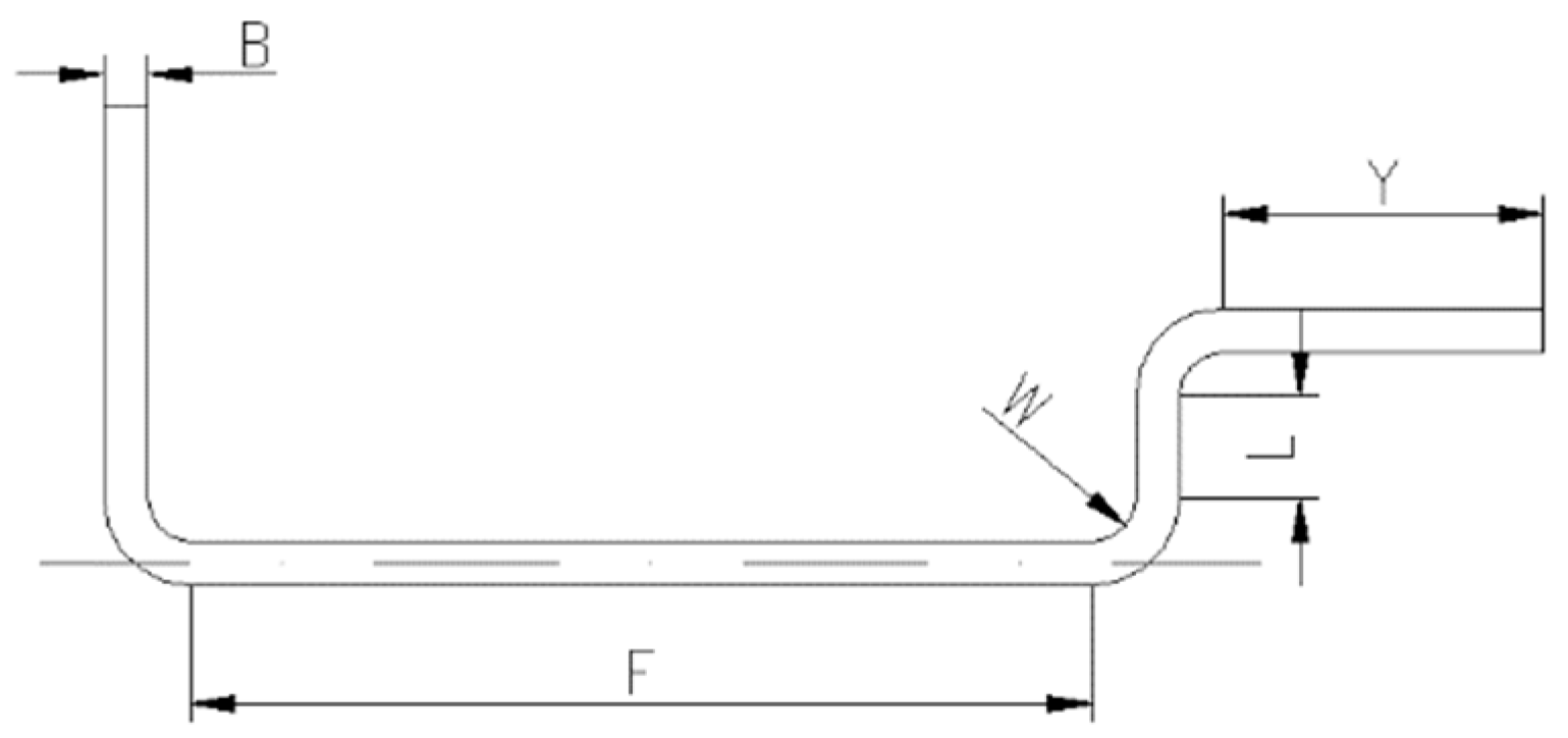
2.3. Study of Geometry Parameter

The model studied in this paper was an asymmetric structure. The asymmetric structure lead to the asymmetrical forces and stress, strain, and torque in the forming process, leading to some unnecessary defects. Therefore, it is necessary to study the influence of the product’s geometric parameters on the torsion defects of cold roll forming. Given the unusual shape of the automobile lower beam, this paper mainly studied five factors, including the web width, flange width, strip thickness, vertical edge height, and corner radius. By comparing the simulation results of each factor’s different values, each element’s influence law on torsion was obtained, which is of great reference value for practical design and production. The parameters, codes, and deals of various variables studied in this paper are shown in Table 4, among which the bold values are the original molding data.

3. Results and Discussion
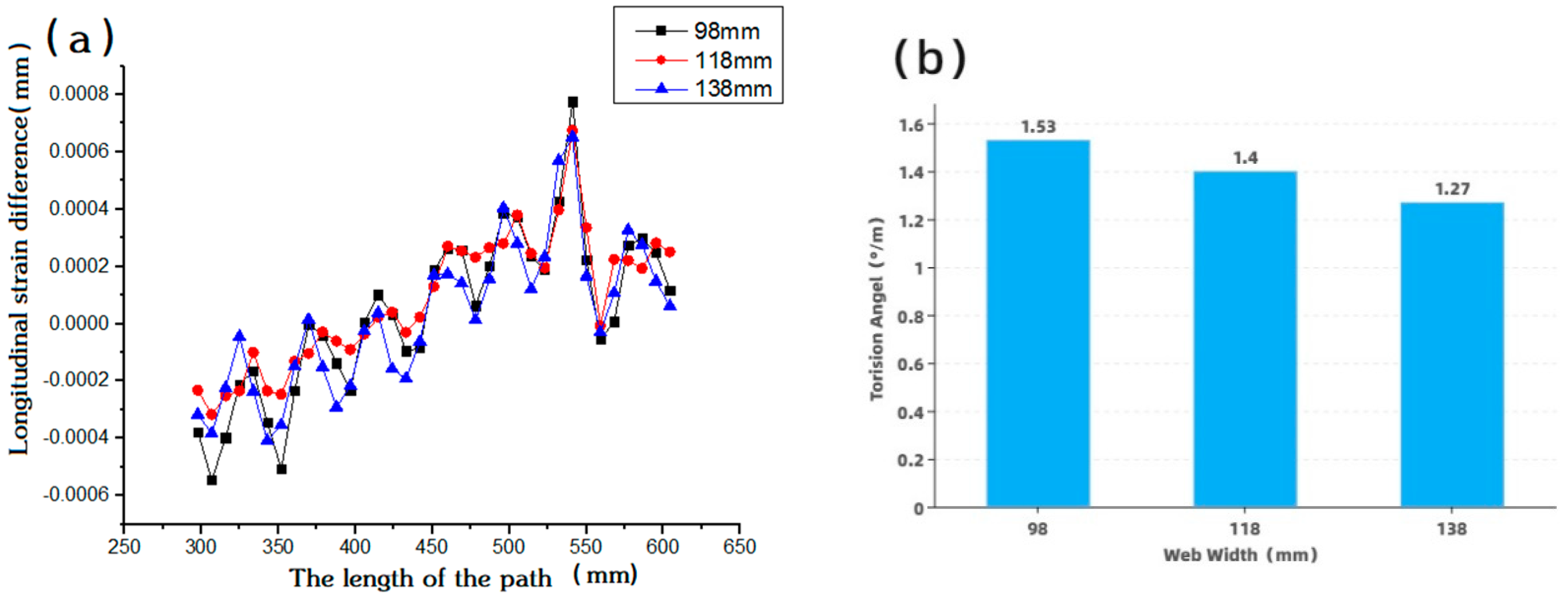
According to scholars’ research results, the more consistent the longitudinal strain change of the edge, the smaller the torsion degree. In this paper, the edge joints’ longitudinal strain on both sides of the automobile’s outer surface lower side beam was extracted. The strain difference was compared with the difference, taken as the assessment standard of the torsion degree. The closer the strain difference was to y = 0, the smaller the torsion. In order to avoid the influence of the end on the result, only the node data of the middle position of the strip were used, and the extraction path is shown in Figure 7. Besides, COCRA software was used for the cross-section extraction of simulation results. This paper directly extracted the cross-section of simulation results to obtain the torsion situation and used it as evidence for the strain difference assessment.

3.1. Web Width

As shown in Figure 8a, the strain differences of different web widths almost coincided. It is difficult to see a significant difference from the figure, but its peak value showed a gradual decrease with the addition of web widths. Regarding the torsion angle obtained from the section of simulation results, it can be seen (as shown in Figure 8b) that with the increase of web width, the degree of torsion eased. For every 20 mm increase of web width on average, the torsion decreased by 0.13°/m. Therefore, it can be concluded that although the web has little effect on torsion, increasing the web width is still beneficial to reduce torsion defects.
The reason for this is that, with regard to the webs of the materials involved in the torsional process, with the increased extension of the web surface materials engaged in torsion, the forming angle, thickness, and other factors will face the same circumstances, and after each iteration, the torque difference will also not change. The adverse effects generated by the torque error (i.e., torsional defects) are absorbed by more web material, thus reducing the degree of torsion on the whole.

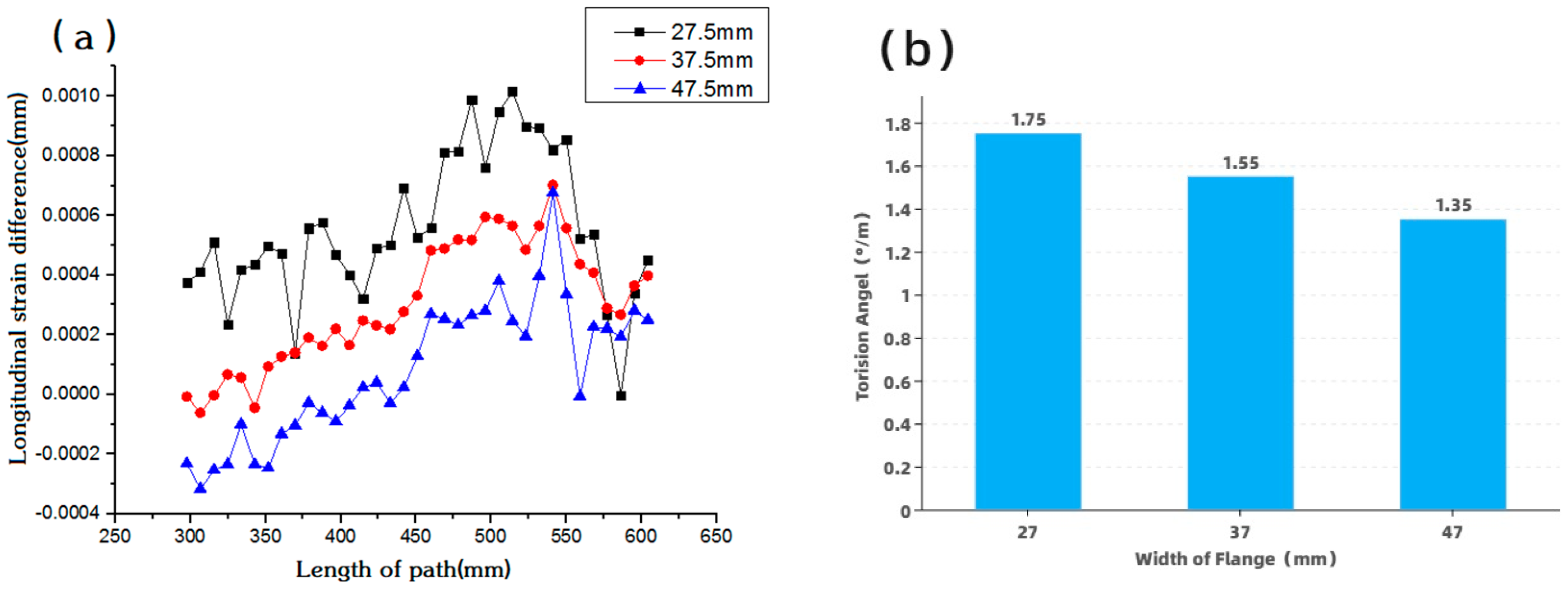
3.2. Width of the Flange

As shown in Figure 9a, with the increase of flange width, the longitudinal strain difference decreased gradually, and the strain difference of F = 47.5 mm was closer to y = 0. The above evidence indicates that the torsion improved with the increase of flange width within a specific range, as verified by cross-section comparison. As shown in Figure 9b, torsion decreased by 0.2°/m with an average 10 mm increase in flange width. Therefore, increasing the width of the right flange is beneficial for reducing torsion.
It was found that the torsion defect did not easily occur in the cold roll forming process of symmetrical section steel. This asymmetrical part is prone to torsion defects because the structure (with increased flanges) destroys the original U-shaped steel’s symmetrical structure. If the flange width is increased, the damage to the symmetrical structure will be more severe. It can be expected that the torsion defect of these parts will be more evident at this time.

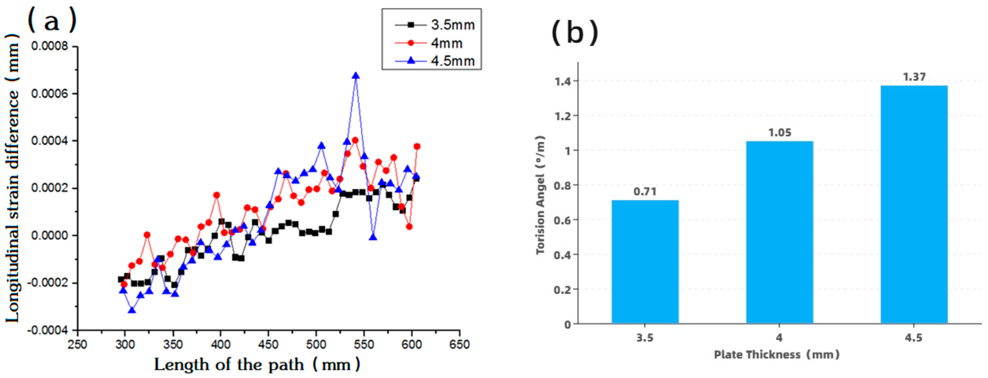
3.3. Plate Thickness

The strain difference corresponding to different thicknesses is shown in Figure 10a. With the decrease of strip thickness, the strain difference distribution gradually approached y = 0; that is, the torsion was improved. The cross-section was extracted to obtain the torsion angle, as shown in Figure 10b. As the thickness of the strip increased, the torsion angle gradually increased, which was consistent with the results of strain analysis. Thus, it can be seen that thickness has a significant effect on torsion in asymmetric forming.
The increase of strip thickness indicates that the larger the forming force required for each pass of forming, the larger the corresponding torque, the larger the overall torque difference, and the greater the longitudinal strain, thus aggravating the torsion defect.

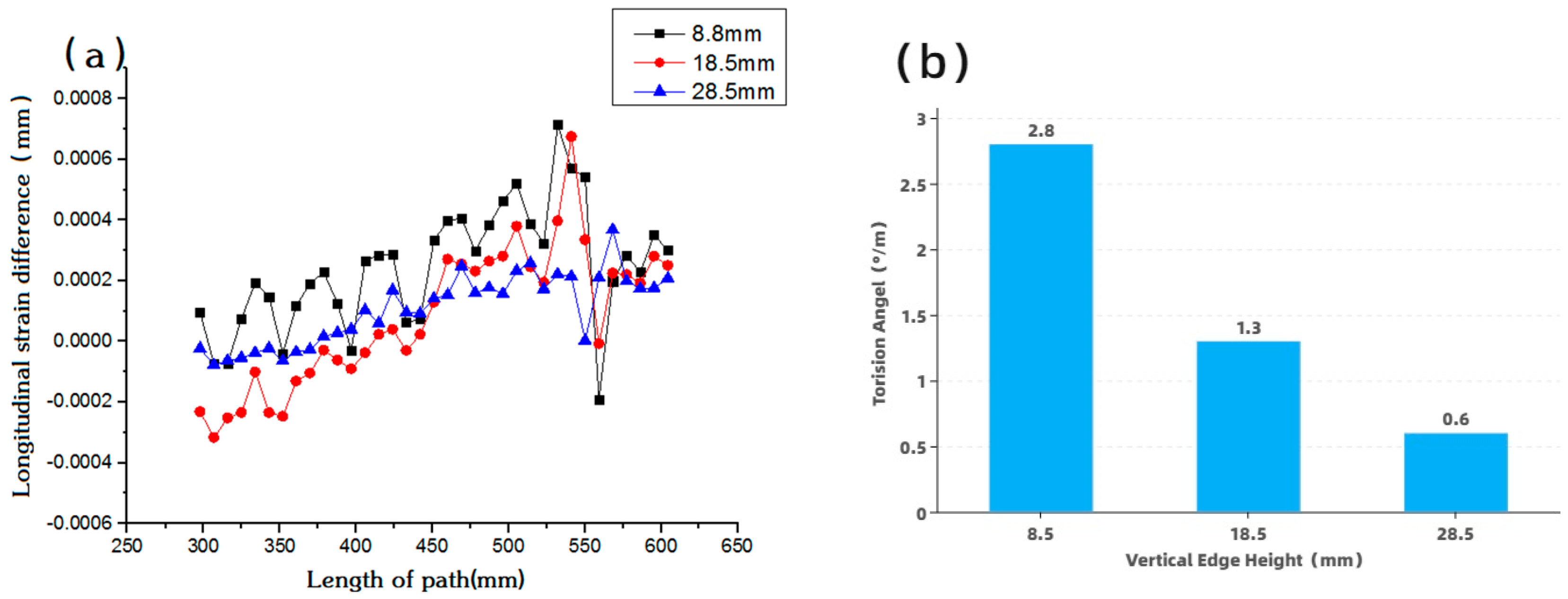
3.4. Vertical Edge Height
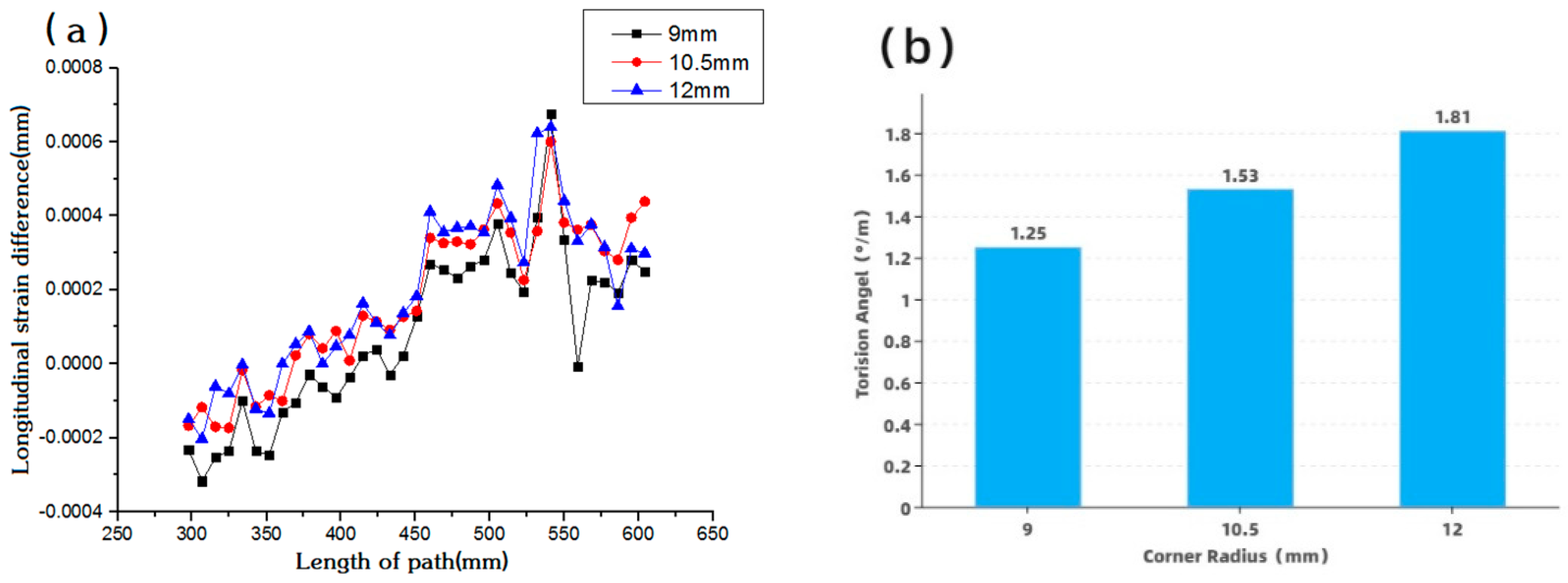
The longitudinal strain difference of the edge with different vertical edge heights is shown in Figure 11a. The strain difference of Y = 28.5 mm was closer to Y = 0, and the strain difference gradually decreased with the increase of vertical edge heights, indicating that the torsion also improved. As shown in Figure 11b, the section’s torsion was enhanced with the increase of the vertical edge height. For every 10 mm expansion of the vertical edge height, the torsion decreased by 1.09°/m. It can be seen that the size of the vertical edge also had an essential effect on the asymmetrical forming torsion defects.
With the increase of the vertical height, the lower beam tended to be symmetrical. This reduced the torque difference between the left and right sides in the forming process and reduced the longitudinal strain difference between the left and right sides to improve the torsion.

3.5. Corner Radius

The longitudinal strain difference of different elbow radii is shown in Figure 12a. With the increase of elbow radius, the strain difference also increased gradually, and the distribution of W = 9 mm moved closer to y = 0. This shows that within a specific range, the smaller the bend’s radius, the smaller the degree of torsion, which is well verified by the cross-section comparison. As shown in Figure 12b, for every 3 mm increase in the bend radius, the torsion improved by 0.28°/m. Therefore, reducing the radius of the bend improved the torsion to a certain extent.
With the increase of corner radius, more material deformation and elastic deformation occurred. With the increase of elastic deformation and the decrease of plastic deformation, the plate’s deformation force increased when it entered the next pass. In this way, the total torque required in the forming process also increased. The corresponding torque difference also expanded, increasing the longitudinal strain and torsion degree.

4. Summary

In this paper, the geometrical factors affecting the cold forming process of the bottom beam of the asymmetric section of a steel truck are studied, which are the width of the web, the width of the flange, the height of the vertical edge, the thickness of the strip, and the radius of the bending angle. Three-dimensional finite element analysis models of 12 stands with 700L sheet material were created using the professional COPRA RF and MSC MARC software. The results show that with the increase of the web width and vertical edge height and the decrease of bend radius and strip thickness, the torsion is improved. Although increasing the short vertical edge’s flange width increases the asymmetry of the lower side beam, it is worth noting that it significantly improves torsion. Of the five geometric factors, strip thickness has the greatest effect on torsion, followed by vertical edge height, and web width has the least impact.

Author Contributions

Conceptualization, J.L., Y.W., B.R.; data curation, J.L., Y.W., X.X. and B.R.; formal analysis, Y.W., X.X. and B.R.; funding acquisition, J.L. and R.Z.; investigation, J.L. and B.R.; methodology, Y.W., J.L.; project administration, J.L. and B.R.; resources, J.L. and R.Z.; software, X.X. and B.R.; supervision, J.L. and Y.W.; validation, J.L.; writing—original draft, Y.W. and B.R.; writing—review and editing, Y.W. and X.X. All authors have read and agreed to the published version of the manuscript.

Funding

This research received no external funding.

Institutional Review Board Statement

Not applicable.

Informed Consent Statement

Not applicable.

Data Availability Statement

The data are contained within the article.

Conflicts of Interest

The authors declare no conflict of interest.

References

  1. Li, Z.; Zhang, Y.; Li, J.; Qin, Y. Roll forming precess design and FEM analysis of automobile anti-collision beam based on copra. In Proceedings of the 15th China CAE Engineering Analysis Technology Annual Conference, Kitakyushu, Japan, 13–16 April 2019; pp. 266–269. [Google Scholar]
  2. Kim, Y.-I.; Kim, J.-H.; Jeoung, Y.-C.; Kim, N.-S. Buckling Analysis of Roll Forming Process using Finite element method. Trans. Korean Soc. Mech. Eng. A 2003, 27, 1451–1456. [Google Scholar] [CrossRef]
  3. Cha, W.-G.; Kim, N. Study on twisting and bowing of roll formed products made of high strength steel. Int. J. Precis. Eng. Manuf. 2013, 14, 1527–1533. [Google Scholar] [CrossRef]
  4. Tajik, Y.; Naeini, H.M.; Tafti, R.A.; Bidabadi, B.S. A strategy to reduce the twist defect in roll-formed asymmetrical-channel sections. Thin-Walled Struct. 2018, 130, 395–404. [Google Scholar] [CrossRef]
  5. Bidabadi, B.S.; Naeini, H.M.; Tafti, R.A. Experimental and numerical study of required torque in the cold roll forming of symmetrical channel sections. J. Manuf. Process. 2017, 27, 63–75. [Google Scholar] [CrossRef]
  6. Moen, C.D.; Igusa, T.; Schafer, B. Prediction of residual stresses and strains in cold-formed steel members. Thin-Walled Struct. 2008, 46, 1274–1289. [Google Scholar] [CrossRef]
  7. Paralikas, J.; Salonitis, K.; Chryssolouris, G. Investigation of the effects of main roll-forming process parameters on quality for a V-section profile from AHSS. Int. J. Adv. Manuf. Technol. 2008, 44, 223–237. [Google Scholar] [CrossRef]
  8. Davoodi, B.; Naeini, H.M.; Asl, Y.D.; Azizi, T.R.; Kasaei, M.M.; Panahizadeh, V.R.; Chinesta, F.; Chastel, Y.; El Mansori, M. Numerical and Experimental Investigation of Roll Forces and Torques in Cold Roll Forming of a Channel Section. AIP Conf. Proc. 2011, 1315, 581. [Google Scholar]
  9. Paralikas, J.; Salonitis, K.; Chryssolouris, G. Energy efficiency of cold roll forming process. Int. J. Adv. Manuf. Technol. 2012, 66, 1271–1284. [Google Scholar] [CrossRef]
  10. Lindgren, M. Cold roll forming of a U-channel made of high strength steel. J. Mater. Process. Technol. 2007, 186, 77–81. [Google Scholar] [CrossRef] [Green Version]
  11. Safdarian, R.; Naeini, H.M. The effects of forming parameters on the cold roll forming of channel section. Thin-Walled Struct. 2015, 92, 130–136. [Google Scholar] [CrossRef]
  12. Wei, L. Finite Element Analysis and Springback Prediction of U Section Steel Bending. Dalian Jiaotong University. 2010. Available online: https://kns.cnki.net/KCMS/detail/detail.aspx?dbname=CMFD2011&filename=2010236935.nh (accessed on 25 August 2021).
  13. Jia, G.; Sun, D.; Wang, R.; Zhao, Y. Production Practice of Medium Plate Large Beam Steel 700L. Hebei Metall. 2019, 2, 59–61. [Google Scholar] [CrossRef]
  14. Liu, X. Research on Springback Prediction and Control of Complex Section Ultra-High Strength Steel in Continuous Roll Bending. University of Science and Technology Beijing. 2018. Available online: https://kns.cnki.net/kcms/detail/detail.aspx?dbcode=CDFD&dbname=CDFDLAST2018&filename=1018224389.nh&v=8UfAKiloKarOQVHTZMOeKFhxTOXuTr7xSTZjaKnilFMeUkSRJFa884hHkH4lnRqc (accessed on 25 August 2021).
  15. Paralikas, J.; Salonitis, K.; Chryssolouris, G. Optimization of roll forming process parameters—A semi-empirical approach. Int. J. Adv. Manuf. Technol. 2009, 47, 1041–1052. [Google Scholar] [CrossRef]
Figure 1. Metallographic diagram of 700L material.
Applsci 11 07852 g001
Figure 2. Geometric dimensions of 700L high-strength steel tensile specimen.
Applsci 11 07852 g002
Figure 3. Cross-section of lower side beam of automobile.
Applsci 11 07852 g003
Figure 4. Automobile lower beam forming, roller flower drawing.
Applsci 11 07852 g004
Figure 5. Setting of boundary conditions of the lower beam model.
Applsci 11 07852 g005
Figure 6. Three-dimensional cold-bending model of automobile lower beam.
Applsci 11 07852 g006
Figure 7. The node was used to extract the path and direction.
Applsci 11 07852 g007
Figure 8. Simulation results of different web widths. (a) Influence of different web width on torsion; (b) Torsion decrease about 0.13°/m with an average 20 mm increase in flange width.
Applsci 11 07852 g008
Figure 9. Simulation results of different widths of the flange. (a) Influence of different width of flange on torsion; (b) Torsion decrease 0.2°/m with an average 10 mm increase in width of flange.
Applsci 11 07852 g009
Figure 10. Simulation results of different plate thicknesses. (a) Influence of different plate thickness on torsion; (b) Torsion increase about 0.3°/m with an average 0.5 mm increase in plate thickness.
Applsci 11 07852 g010
Figure 11. Simulation results of different vertical edge heights. (a) Influence of different Vertical edge height on torsion; (b) The torsion increases with the height of the vertical edge.
Applsci 11 07852 g011
Figure 12. Simulation results of different corner radii. (a) Influence of different corner radius on torsion; (b) Torsion decrease about 0.28°/m with an average 1.5 mm decrease in corner radius.
Applsci 11 07852 g012
Table 1. Chemical composition of 700L material (wt%).
CSiMnCr + MoBNb + V + Ti
0.07≤0.30≤2.00≤0.80≤0.0020≤0.10
Table 2. Tensile test results of 700L high-strength steel (thickness 4.5 mm).
Thickness
(mm)
Direction of RollingYield Strength
(MPa)
Tensile Strength
(MPa)
Elongation after Breakage
(A/%)
Modulus of Elasticity
(GPa)
4.5Transverse649.7771.723.1214
Longitudinal631.2749.323.5209
Table 3. Forming angle distribution of automobile lower beam.
Pass1234567891011
Forming Angle/°012253545556575838890
Table 4. Geometric factor parameter table.
Geometric FactorCode NumberUnitValue
Web widthFmm98118138
Flange widthYmm27.537.547.5
Plate thicknessBmm3.54.04.5
Vertical edge heightLmm8.518.528.5
Corner radiusWmm910.512
Publisher’s Note: MDPI stays neutral with regard to jurisdictional claims in published maps and institutional affiliations.

