Article

A Study on the Manufacture of Permanent Magnet Traction Control Valve for Electronic Stability Control in Electric Vehicles

1
R&D Center, SUNGJIN FO-MA Inc., 93 dalseodaero 109 gil, Dalseo-gu, Daegu 42710, Korea
2
Extreme Fabrication Technology Group, Korea Institute of Industrial Technology, 320 Techno sunhwan-ro, Yuga-myeon, Dalseong-gun, Daegu 42994, Korea
3
Tech Center, erae Automotive Systems Co., Ltd., 664 Nongong-ro, Nongong-eup, Dalseong-gun, Daegu 42981, Korea
4
School of Mechanical Engineering, Kyungpook National University, Daugu 41566, Korea
*
Author to whom correspondence should be addressed.
Appl. Sci. 2021, 11(17), 7794; https://doi.org/10.3390/app11177794
Submission received: 29 June 2021 / Revised: 20 August 2021 / Accepted: 22 August 2021 / Published: 24 August 2021

Abstract

:
Most solenoid valves in use today require a magnetic coil to be continuously energized to maintain the magnetization of the magnetic body in order to operate. The problem is that if the power is still supplied, the power consumption will continue. In addition, problems such as shortening the lifespan of solenoid valve internal parts due to the increase in the internal temperature of the electronic stability control (ESC) due to the continuous heating of the magnetic coil, and malfunction due to instantaneous power failure may occur. In this study, we conducted a study on the permanent magnet traction control valve (TCV) for ESC that can minimize the unnecessary power consumption of electric vehicle batteries. For optimal permanent magnet design, polarity direction setting and permanent magnet specifications were studied through FE simulation. A permanent magnet TCV was fabricated and an electromagnetic force test was conducted to compare and evaluate it with the FE simulation result. By using a permanent magnet, it was possible to lower the initial current value for the TCV to drive, therefore, it was possible to develop a permanent magnet TCV that can minimize the unnecessary power consumption of electric vehicle batteries.

1. Introduction

Currently, the automobile industry is rapidly changing from an internal combustion engine vehicle to an electric vehicle. With the transition to electric vehicles, there has been a change in the main raw material source from petroleum energy to electric energy. Efforts are being made to improve fuel efficiency in electric vehicles as in internal combustion engine vehicles. Since most parts of an electric vehicle are operated by receiving power from a battery, it is necessary to manufacture parts that minimize the use of batteries. In this study, the traction control valve (TCV) for electronic stability control (ESC), an active safety system component for electric vehicles, was designed and manufactured as a component that minimizes the use of batteries. In automobiles, technologies such as advanced safety devices and convenience devices are continuously being developed, and in particular, technology development in the field of passenger and pedestrian safety greatly contributes to the reduction of traffic accidents [1,2,3,4,5,6]. As a result, electric vehicles are attracting a lot of attention because of their higher efficiency, lower emissions, and various safety device features compared to internal combustion engine vehicles [7,8,9,10,11,12,13]. When the driver brakes or turns the vehicle in a direction different from the command, ESC detects this from sensors installed in the braking and steering system to functionally compensate for anti-locking brake system (ABS) and brakes each wheel independently. This helps maintain braking and directional stability. As shown in Figure 1a, the ESC controls the brake unit for each wheel through an electronic control unit (ECU), pump, and solenoid valves installed in a hydraulic electronic control unit (HECU) [14,15,16]. As shown in Figure 1b, the solenoid valves applied to ESC include inlet solenoid valve (IV), outlet solenoid valve (OV), electric shuttle valve (ESV), and TCV. It has a brake function when the vehicle is stopped, an auto-hold function that eliminates the need to press the brake pedal when waiting at a traffic light, and a solenoid valve to prevent slipping on slopes. Of the four solenoid valves, this is the TCV. As shown in Figure 2a, since the conventional TCV had to continuously supply power during the operation maintenance period after power on, the life of the electric system was shortened due to heat generation and power consumption. Solenoid valves up to now have a structure and method similar to those of conventional TCVs. The on/off solenoid valve that opens and closes the flow path or the proportional control solenoid valve that controls the flow rate by current has been mainly studied. Sung derived the governing equations for optimal on/off solenoid design and developed a design program consisting of electromagnetic theory and experimental parameter values [17]. Wu et al. studied the modeling, optimization, and validation methods of a hollow plunger-type solenoid for a high-speed on/off valve [18]. Branciforte et al. presented an electrical model of an on/off solenoid valve used to regulate brake pressure in an anti-lock braking control system (ABS) [19]. Yun et al. inferred and analyzed the factors affecting the performance of proportional solenoids, and studied how to select magnetic materials [20,21,22]. Tanaka studied the dynamic characteristics of the proportional solenoid and designed the solenoid to be automatically adjusted to the target performance [23]. However, for the on/off and proportional control type solenoid valve, it was necessary to maintain the magnetization of the magnetic material by continuously applying power to the magnetic coil. The problem is that the power consumption goes up when the power is still supplied. In addition, problems such as shortening of the lifespan of solenoid valve internal parts due to the increase in the internal temperature of the ESC due to the continuous heating of the magnetic coil and malfunctions due to instantaneous power failure may occur. To compensate for this, a permanent magnet TCV has been studied so that it does not lose its function even if the power is cut off during the TCV operation period, as shown in Figure 2b. The auto-hold function of the car was able to maintain the braking function by the permanent magnet even if the power is cut off after the TCV operation. After initial power is applied and the valve is actuated, even if the power is cut off during the maintenance period, the permanent magnet can maintain its function, reducing power consumption as no additional power is supplied. In addition, since the power is cut off during the auto-hold period, it has the advantage of reducing the heat generation of the magnetic coil and minimizing the shortened lifespan due to the internal temperature rise. Solenoid valves studied so far have focused on the magnitude and characteristics of electromagnetic force. In addition, research was conducted to confirm the electromagnetic characteristics according to the material properties and specifications of the magnetic material, and to suggest the optimal solenoid valve design method. Lee et al. conducted an optimal design study to predict and experimentally verify the electromagnetic force of a solenoid valve for a hydrogen-fueled electric vehicle through electromagnetic field analysis [24]. Liu, Sun, and Hung studied the structure of a solenoid magnetic material and the change in electromagnetic force according to the change of the air gap [25,26,27]. Tao and Bayat studied the optimal solenoid valve design by experimentally analyzing the B-H curves of various soft materials and taking into account the change in the electromagnetic force according to the shape [28,29]. Wang et al. used FEA to study the effect of magnetic cross-sectional area and magnet coil specifications of solenoid valves on static electromagnetic properties. He also simulated the dynamic process of a solenoid valve to quantitatively understand the effect of solenoid valve parameters on the dynamic response characteristics [30]. However, previous studies have studied the properties of electromagnetic force through FE simulation using the structure of the solenoid valve and the shape and material properties of magnetic materials. The product was manufactured based on FE simulation and verified through test evaluation. Through this study, a solenoid valve applied with a permanent magnet was studied through FE simulation. The magnetic force, electromagnetic force, and their resultant force were studied and evaluated according to the polarity direction and specification of the permanent magnet. A permanent magnet TCV was manufactured and an electromagnetic force test was conducted to compare and evaluate it with the FE simulation result. In order to check whether the braking function is maintained by the permanent magnet even when the current is cut in the auto-hold function of the TCV, a test evaluation was conducted under actual vehicle conditions. Also, by using a permanent magnet, it was possible to lower the initial current value for the TCV to drive. Therefore, it was possible to develop a permanent magnet TCV that can minimize the unnecessary power consumption of electric vehicle batteries.

2. Design of the Permanent Magnet TCV

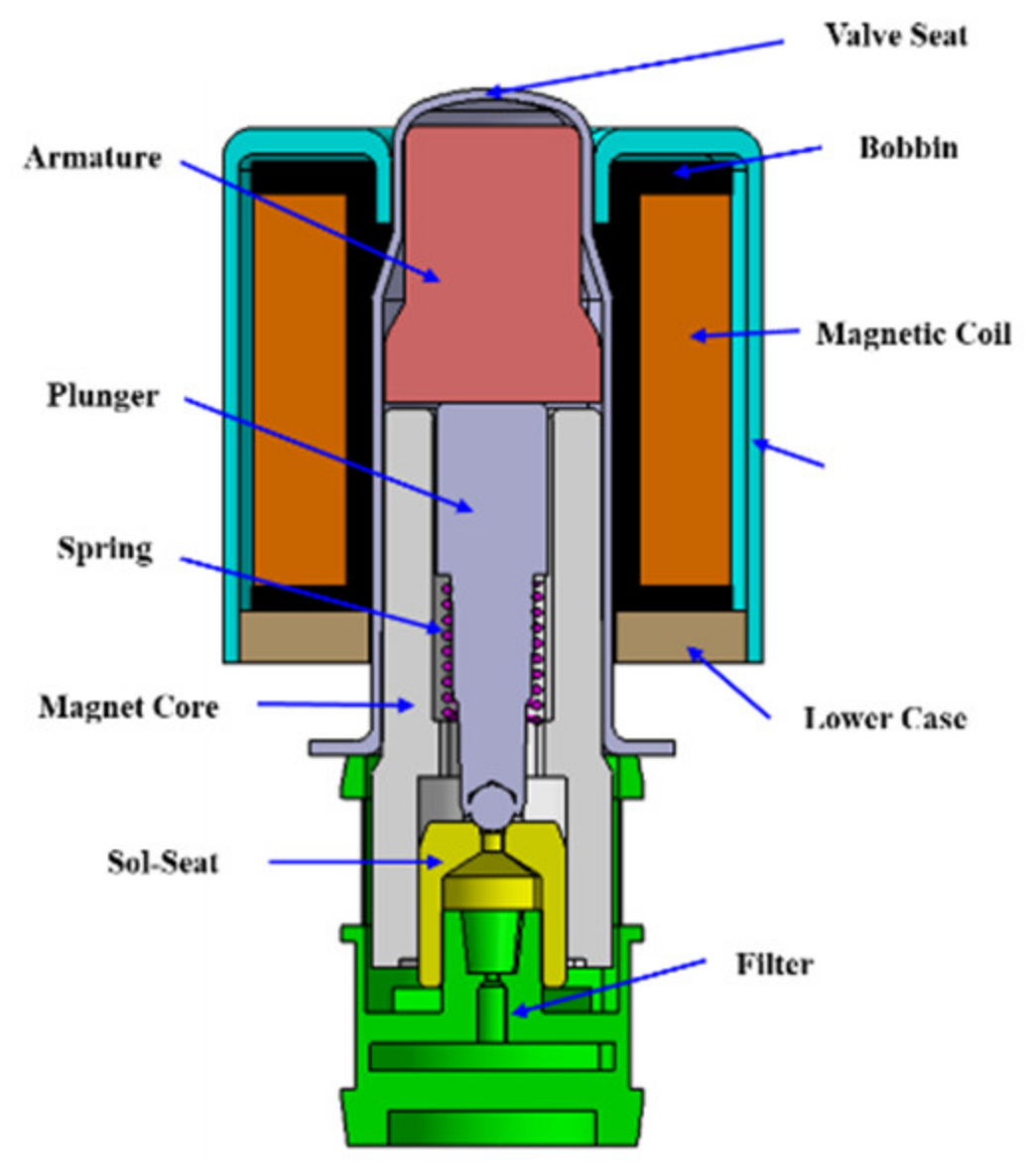
2.1. Schematic of the Conventional TCV

The currently widely used TCV for ESC has the structure shown in Figure 3. Among them, the armature, magnet core, upper case, and lower case are magnetic materials that are magnetized when power is applied. The magnetic body is made of materials with high magnetic flux density and low magnetic flux strength, and most of them are made of low carbon steel materials such as S10C. The armature, magnet core, and cases are magnetized by applying 3.4 A to the magnetic coil. This induces the armature to be adsorbed to the magnet core, pushing the plunger downwards to block the hole in the sol-seat. The hole in the sol-seat is blocked, and the flow of brake fluid is blocked. When the power supply is interrupted, the magnetic material is demagnetized. At this time, the plunger opens the flow path of the sol-seat by pushing the armature upward by the reaction force applied by the spring. However, in order to block the flow of brake oil in sol-seat in TCV for ESC, current must be continuously supplied. Continuous current supply generates heat in the magnetic coil and increases power consumption. If the auto-hold function is used for 2 h a day while driving an electric vehicle, the power consumption is about 82.3Wh. The heat generated by the magnetic coil rises up to a maximum of 200 °C, which in turn raises the temperature inside the ECU up to a maximum of 150 °C Therefore, in order to prevent the temperature rise of the magnetic coil, the initial current is lowered to 1.5 A after applying 3.4 A to prevent the temperature rise of the magnetic coil.
Figure 4a shows a state in which the flow path of the sol-seat is open because power is not supplied to the magnetic coil. At this time, the distance between the armature and the magnet core is 0.47 mm and the distance between the plunger and the sol-seat is 0.30 mm. Figure 4b shows the closed state of the flow path of the sol-seat. When power is applied and the plunger closes the flow path of the sol-seat, the distance between the armature and the magnet core is 0.17 mm. When power is applied and the plunger closes the flow path of the sol-seat, the distance between the armature and the magnet core is 0.17 mm. The reason to keep the 0.17 mm gap between the armature and the magnet core is to prevent the noise caused by the contact of the two metal objects. It also has the responsiveness to quickly separate the residual electromagnetic force generated between the armature and the magnet core when the power is cut off.

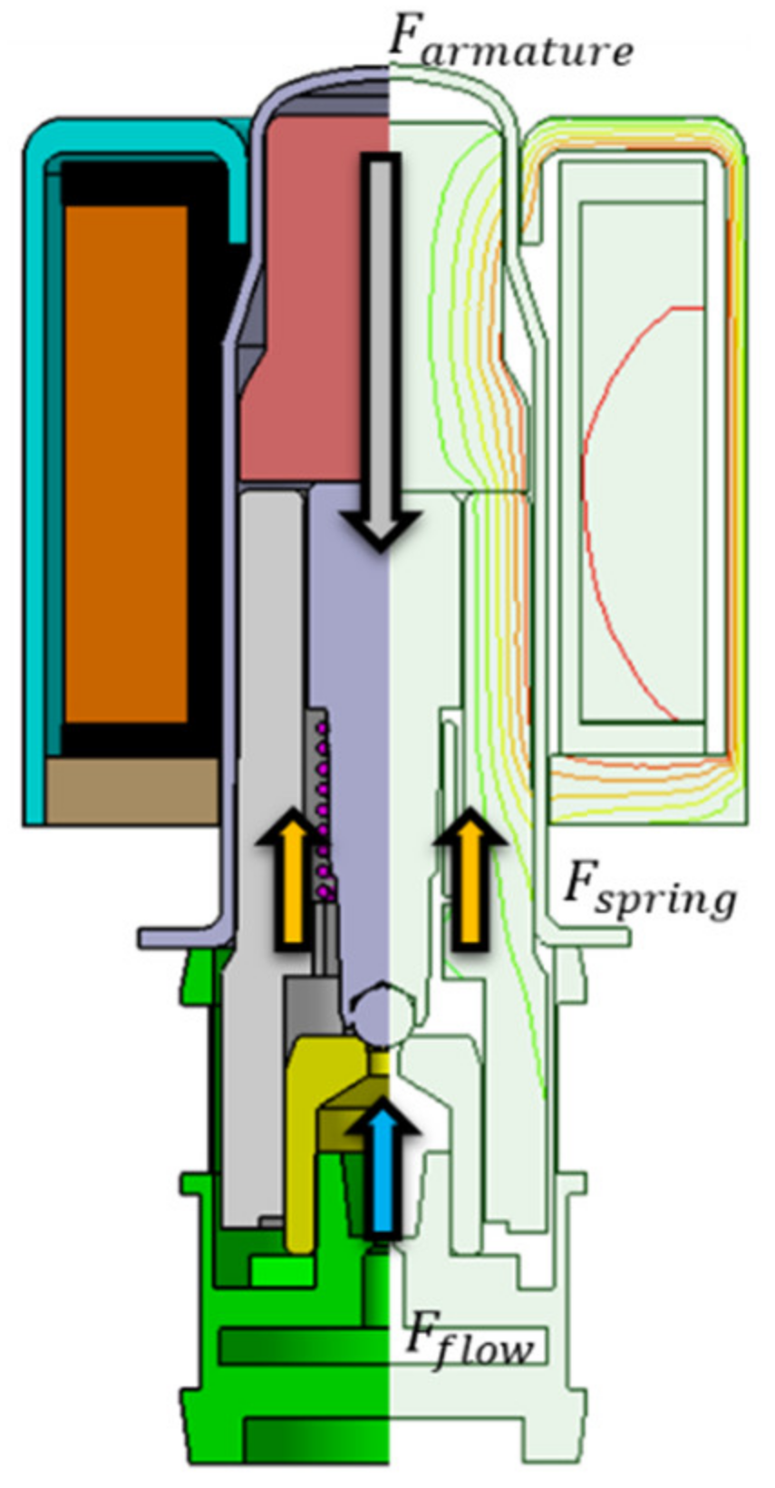
2.2. Required TCV Electromagnetic Force

When current flows through the TCV, the plunger must calculate the required electromagnetic force between the armature and the magnet core to block the flow path of the sol-seat. If the force applied to the plunger by the internal pressure of the valve is Ff, the spring load is Fs, and the margin factor for securing the reliability of TCV operation is c, the electromagnetic force Fa, required for TCV can be expressed as (1).
F a = c [ F f + F s ]
Here, if the free length of the spring is lf, the setting length is ls, and the spring constant is K, the load, Fs, of the spring can be expressed as (2).
F s = F 1 + ( l f l s ) K
Figure 5 shows the load distribution of armature, spring, and hydraulic pressure to confirm the electromagnetic force required for TCV. Since the hole diameter of the sol-seat is Ø0.7, the maximum operating load Ff of the valve at 60 bar was 2.3 N. With a free length of 6 mm, a set length of 4.7 mm, and a spring constant of 0.3 N/mm, the spring load Fs is 0.39 N by Equation (2). Here, if the reliability margin is set to 20%, the electromagnetic force required for the TCV is determined to be 3.2N by Equation (1).

2.3. Schematic of the Permanent Magnet TCV

As shown in Figure 6, the permanent magnet TCV places the permanent magnet in the flow section of the magnetic flux line generated by the magnetic material when power is applied. Therefore, permanent magnets can be placed between the armature, the magnet core, the upper case, and the lower case. The design of the permanent magnet TCV was accomplished by replacing the lower case with a permanent magnet in the conventional TCV. Here, the force of the permanent magnet is expressed as the magnetic force, the force of the TCV itself excluding the permanent magnet is the electromagnetic force, and the resultant force of the magnetic force and the electromagnetic force is expressed as the total electromagnetic force. When a current of 3.4 A is applied to the magnetic coil, the armature moves to the magnet core by magnetic force, blocking the flow path of the sol-seat. Even if the power supply is cut off, the armature remains magnetized without being separated from the magnet core by the magnetism of the permanent magnet. Therefore, heat generation of the magnetic coil can be prevented because the flow path of the sol-seat is blocked when power is not supplied. In addition, unlike conventional TCV, a continuous power supply is not required, which reduces power consumption. However, in order for the armature to return to its original position, the total electromagnetic force between the armature and the magnet core must be 0 N. Due to the polarized permanent magnet, a reverse current must be applied to make the total electromagnetic force between the armature and the magnet core 0 N.

2.4. Design of the Magnet Coil Winding

The electromagnetic force can be expressed as (3) as the product of the number of rotations N of the magnetic coil generating magnetic flux and the current I flowing through the magnetic coil.
U = N I
Figure 7 is a simplified representation of a bobbin and a magnetic coil wound around the bobbin. If the inner diameter of the bobbin is Bi, the outer diameter is Bo, the height h, and the diameter of the enamel wire is cd, the number of coil winding stacks in the bobbin axial direction, nc, and the number of coil winding stacks in the bobbin radial direction, mc, are as shown in (4) and (5). The number of coil turns can be expressed as (6) as the product of the number of stacks in the radial and axial directions.
n c = h c d 1
m c = w c d
N = n c m c
The current flowing in the magnetic coil can be expressed as (7) using the copper wire diameter Nd excluding the insulating layer of the enamel wire, the resistivity ρ , and the average length lca of the one-turn coil winding [31].
I = V 4 ρ l c a N π N d 2
In the magnetic coil design, the design conditions that affect the TCV electromagnetic force are the inner diameter, outer diameter, bobbin height, applied voltage, and the diameter of the enameled wire. Magnetic coil rotation is a factor that affects the electromagnetic force when voltage and resistance are fixed. The conducting and overall diameter were chosen to fill the magnetic coil to the maximum within the bobbin space. Therefore, the design elements of the magnetic coil assembly are shown in Table 1.
Figure 7. Schematic of the magnetic coil winding.
Applsci 11 07794 g007

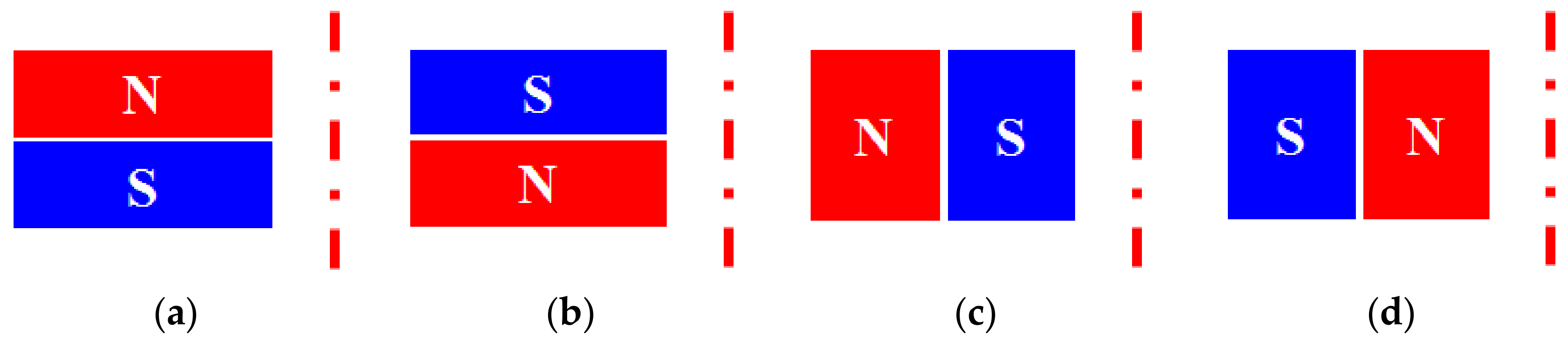
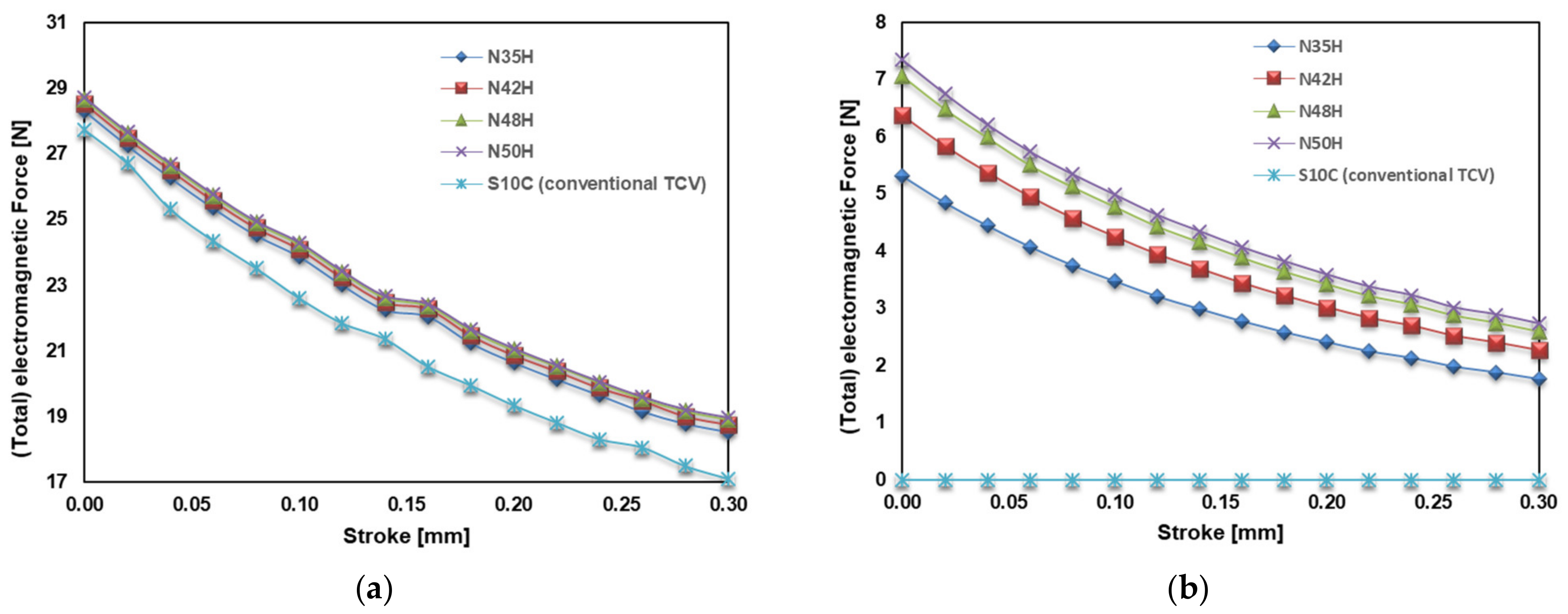
2.5. Design of the Permanent Magnet

In order to set the polarity direction of the permanent magnet, it was designed with four conditions, as shown in Figure 8. The polarity design condition of the permanent magnet is that even if the magnetic coil power is cut off, the magnetic force between the armature and the magnet core must be maintained over a certain level. Total electromagnetic force analysis was performed using a Maxwell V14 for the four polarities of a permanent magnet. A two-dimensional (2D) axisymmetric model was used for TCV. Figure 9 shows the total electromagnetic force according to the polarity of the permanent magnet by applying the N-35H standard of Nd-Fe-B material to the permanent magnet. In Figure 8a,b, when the polarity of the permanent magnet is located at the top and bottom, the total electromagnetic force is 0 N at the current 0 A, as shown in Figure 9. In the TCV with a permanent magnet in Figure 8a or Figure 8b, when power is applied, the armature moves to the magnet core, and when the power is cut off, the armature returns to its original position. Therefore, if the polarity of the permanent magnet is located at the top and bottom, the function of the conventional TCV is similar. As shown in Figure 8c,d, when the polarity of the permanent magnet is located at the inner diameter and outer diameter, the total electromagnetic force becomes more than 6 N at 0 A, as shown in Figure 9. In a TCV with a permanent magnet in Figure 8c,d, the armature moves to the magnet core when power is applied. However, even if the power is cut off, the magnetic force of the permanent magnet will not return the armature to its original position. Therefore, the polarity direction of the permanent magnet can be set to (c) or (d) in Figure 8.
The permanent magnet design is shown in Figure 10. According to the polarity direction results in Figure 8 and Figure 9, the inner diameter was set to N pole and the outer diameter to S pole. In addition, the small size of the permanent magnet facilitates magnetization and is designed with four sections in the axial direction to minimize material loss. To design the specifications of permanent magnets, total electromagnetic force analysis was performed for each permanent magnet specification. The material of the permanent magnet was selected as Nd-Fe-B. The designs were reviewed by applying N-35H, N-42H, N-48H, and N-50H according to the residual magnetic flux density and coercive force that affect the total electromagnetic force. Table 2 shows the residual magnetic flux density and coercive force values for each permanent magnet.
Total electromagnetic force analysis was performed from an initial air gap of 0.47 mm between the armature and the magnet core to a stroke of 0.30 mm with the plunger moving. In the conventional TCV, the lower case material was applied as S10C and the electromagnetic force analysis was performed. Permanent magnet TCV has applied permanent magnets of N-35H, N-42H, N-48H, N-50H specifications to the lower case. Figure 11 shows the comparison of electromagnetic force and total electromagnetic force according to the stroke of the conventional TCV and the TCV to which the permanent magnet specification is applied. Figure 11a shows the results of the electromagnetic force and total electromagnetic force for each stroke when a current of 3.4 A is applied to the TCV. At 0.30 mm stroke, the total electromagnetic force was about 11.8% higher in permanent magnet TCV than conventional TCV and about 3.6% higher in 0mm stroke. Because the total electromagnetic force of permanent magnet TCV is higher than that of conventional TCV, the initial use current can be lower than 3.4 A. However, the total electromagnetic force of TCV with permanent magnets of the N-35H, N-42H, N-48H, and N-50H specifications at 3.4 A were similar. As shown in Figure 11b, the conventional TCV does not generate any electromagnetic force at 0 A when the TCV is de-energized. Permanent magnet TCV exhibited a magnetic force of more than 5 N at 0 mm distance between plunger and sol-seat. TCV with N-50H specification permanent magnets showed the highest magnetic force of about 7.3 N. Therefore, the permanent magnet specification is designed as N-50H, which shows the highest magnetic force at 0 A when no current is supplied.
Figure 12 shows the electromagnetic force simulation results of the conventional TCV. Figure 12a,b shows the results of magnetic flux density and magnetic field strength when a current of 3.4 A is applied to the conventional TCV. This is the result at 0 mm of stroke where the plunger completely closes the sol-seat flow path. At 0 A, when no current is applied, the magnetic flux density and magnetic field strength are zero. Figure 13 shows the electromagnetic force for each stroke applying a current from −3.4 A to 3.4 A. Conventional TCV showed the same value in left-right symmetry with respect to 0A.
Figure 14 and Figure 15 show the total electromagnetic force analysis results of TCV with N-50H permanent magnet applied. Figure 14 shows the magnetic flux density and magnetic flux strength at 3.4 A and 0 A. In the conventional TCV, the magnetic flux density and magnetic flux strength did not appear at 0 A, but in the permanent magnet TCV, the magnetic flux density and magnetic flux strength appeared even when no current was supplied. However, in the permanent magnet TCV, the magnetic flux density and magnetic flux strength were exhibited by the permanent magnet as shown in Figure 14c,d even when no current was supplied. Because the magnetism of permanent magnets is directional, a reverse current was supplied, as shown in Figure 15, to interrupt the flux flow between the magnetic material and the permanent magnet. Conventional TCV showed the same electromagnetic force at −3.4 A and 3.4 A. However, for the permanent magnet TCV, the magnetic flux density and magnetic flux strength were greater when supplying a current of 3.4 A than −3.4 A. Figure 16 shows the total electromagnetic force for each stroke applying a current from −3.4 A to 3.4 A. Due to the permanent magnet, even if the current is cut off at the point where the stroke of the plunger and sol-seat is 0 mm, the magnetic force of 7.3 N is maintained and it can withstand the hydraulic brake pressure of 3.1 N. When the current is cut off in the conventional TCV, the armature returns to its original position by the spring because the electromagnetic force between the plunger and the magnet core becomes 0 N. However, the permanent magnet TCV needs to supply reverse current to make the total electromagnetic force between the armature and the magnet core 0 N, and the armature returns to its original position by the spring. When the armature returns to its initial position (stroke 0.30 mm), the magnetic force between the armature and the magnet core of the permanent magnet TCV is 2.7 N. The hydraulic and spring force is greater than the magnetic force, so the armature cannot move to the magnet core by the magnetic force of the permanent magnet. So, here’s how the permanent magnet TCV works:
(1)
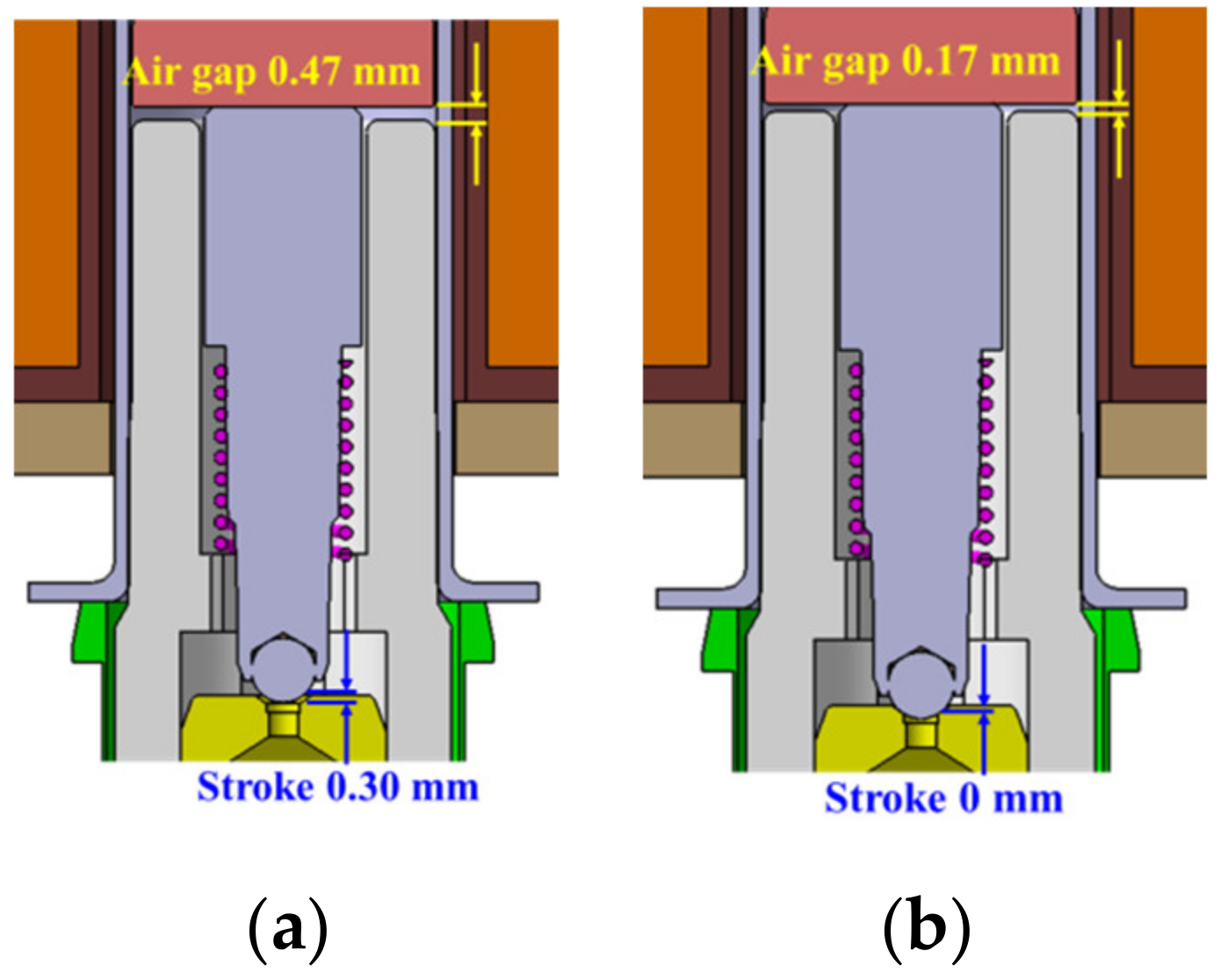
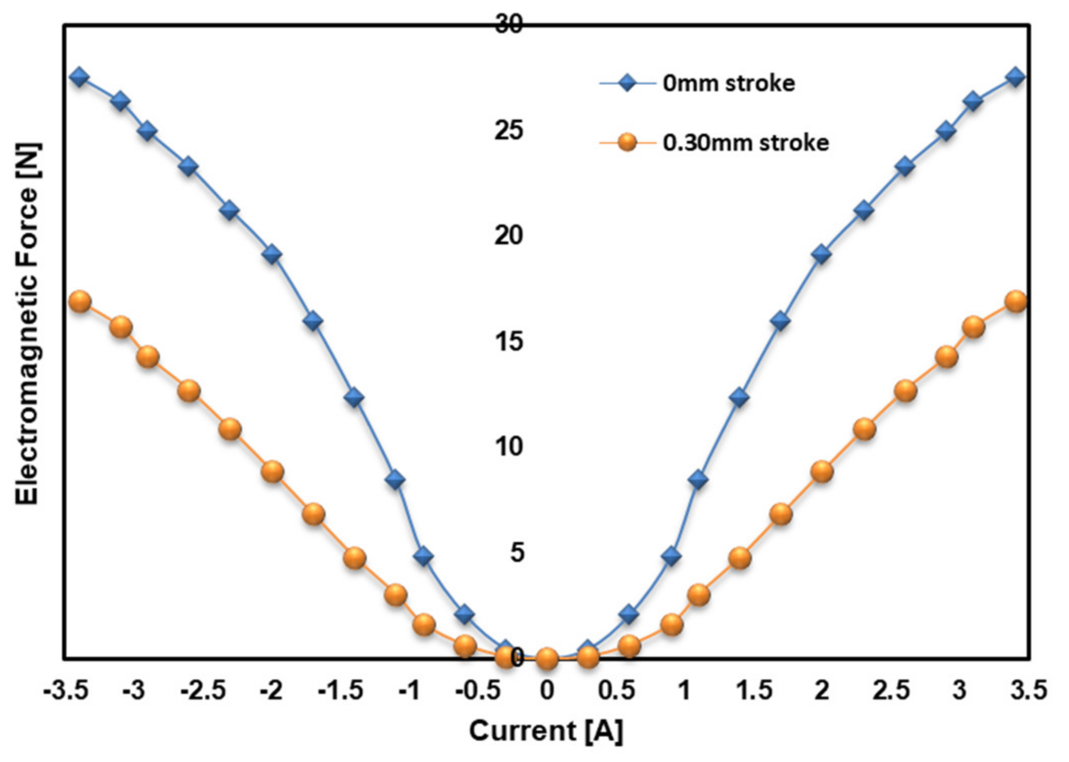
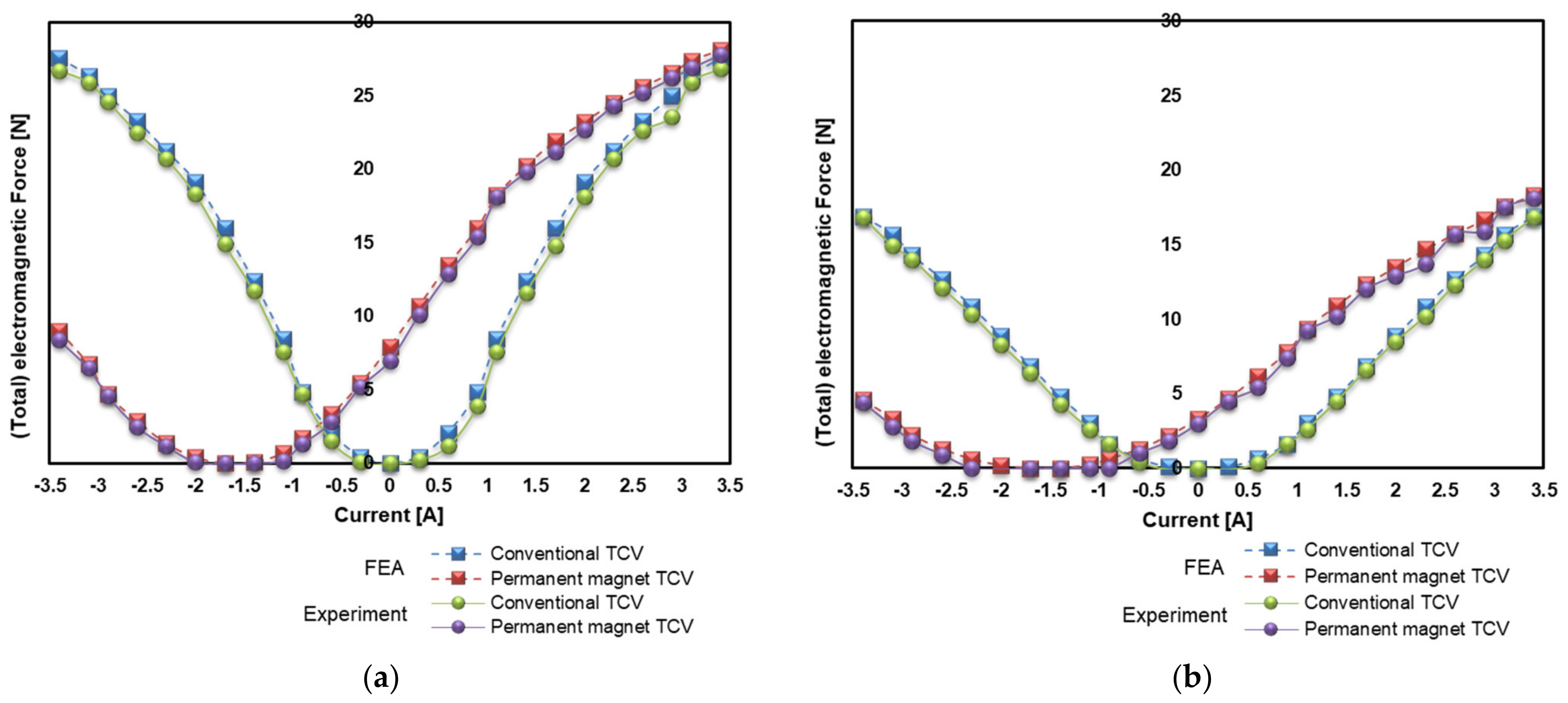
Applying a current of 3.4 A to the permanent magnet TCV generates a total electromagnetic force of 20 N at 0.30 mm stroke, and the armature can move to the magnet core.
(2)
At stroke 0 mm, even if the current is cut off, the armature cannot return to its original position due to the magnetic force of the permanent magnet of 7.3 N.
(3)
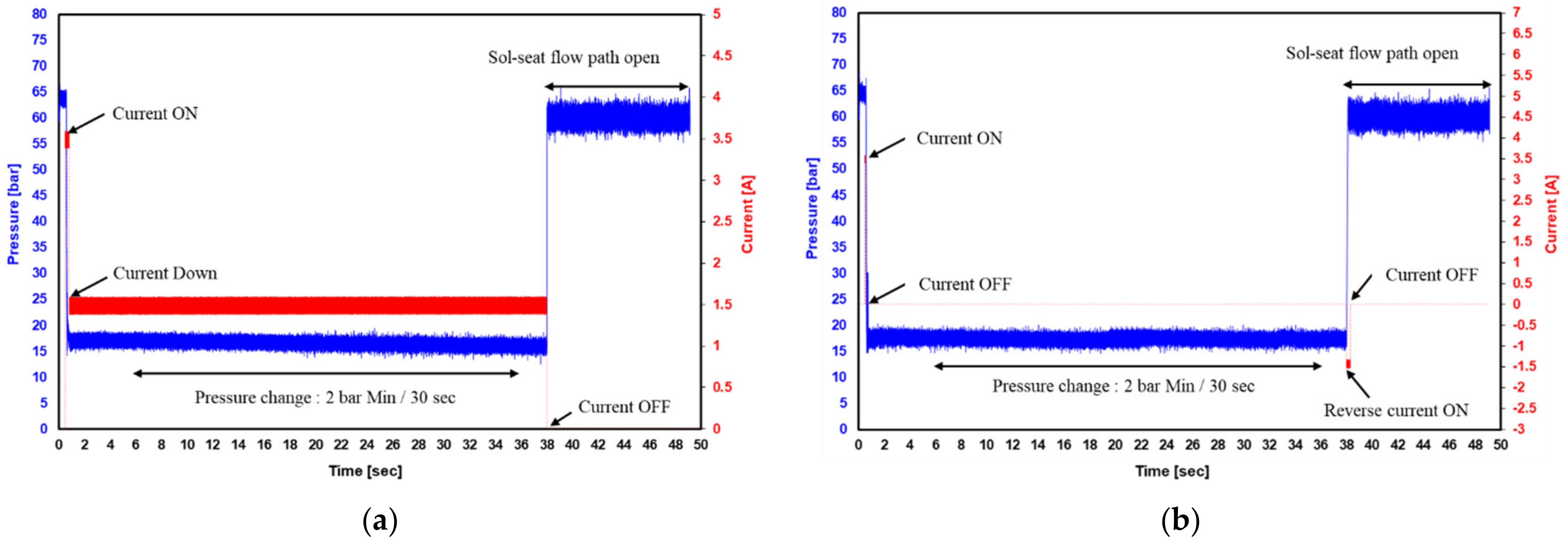
A current of −1.4 A is supplied to make the total electromagnetic force between the armature and the magnet core close to 0 N.
(4)
At this time, the armature can return to the initial position by the spring reaction force, and when returning to the initial position, the reverse current is cut off.
Figure 14. Permanent magnet TCV: (a) magnetic flux density at 3.4 A; (b) magnetic field strength at 3.4 A; (c) magnetic flux density at 0 A; (d) magnetic field strength at 0 A.
Applsci 11 07794 g014
Figure 15. Permanent magnet TCV: (a) magnetic flux density at −1.4 A; (b) magnetic field strength at −1.4 A; (c) magnetic flux density at −3.4 A; (d) magnetic field strength at −3.4 A.
Applsci 11 07794 g015
Figure 16. Total electromagnetic force for each stroke in the permanent magnet TCV.
Applsci 11 07794 g016

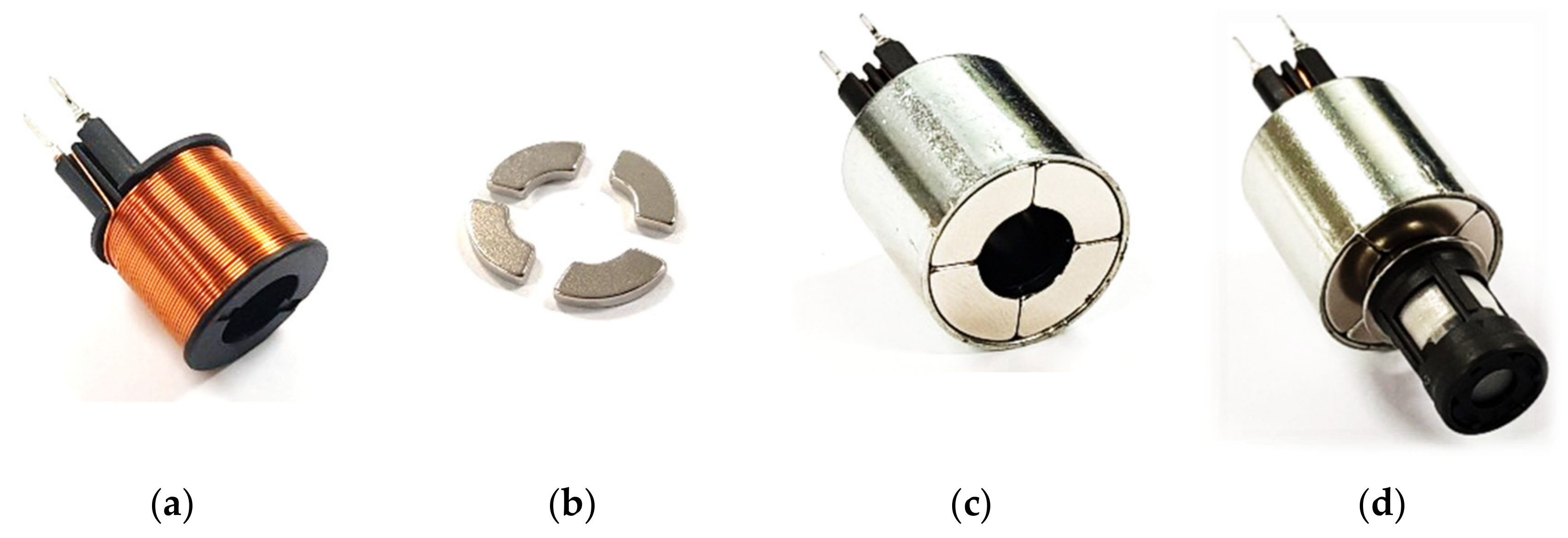
3. Product Manufacturing and Performance Evaluation

The diameter of the magnetic coil was Φ0.3, and 36.5 layers ∗ 10 steps were wound on the bobbin to manufacture the magnetic coil winding as shown in Figure 17a. Figure 17b is a permanent magnet made of Nd-Fe-B material in N-50H standard and manufactured in 4 divisions. As shown in Figure 17c, a coil assembly was fabricated by assembling a four-part permanent magnet instead of the lower case of the conventional TCV. A permanent magnet TCV was fabricated, as shown in Figure 17d, to experimentally confirm the performance evaluation of the actual vehicle condition by applying the total electromagnetic force and hydraulic pressure of the TCV.
As shown in Figure 18, the experimental device to check the total electromagnetic force of TCV uses a 1-ton servo press to control the stroke, which is the distance between plunger and sol-seat. From the simulation results in Figure 13 and Figure 16, the total electromagnetic force of TCV was confirmed to be less than 50N, and a load cell capable of measuring up to 50N was mounted on the servo press. In addition, a power supply device was prepared to check the total electromagnetic force for each current. Conventional TCV and permanent magnet TCV were manufactured and tested. Figure 19a is the result of comparing the total electromagnetic force for each current at stroke 0 mm with simulated and experimental values. Figure 19b shows the total electromagnetic force at a stroke of 0.30 mm. It was confirmed that the total electromagnetic force for each current at 0 mm and 0.30 mm strokes was similar to the simulated and experimental values. The total electromagnetic force of permanent magnet TCV and the electromagnetic force of conventional TCV was similar at 3.4 A. The permanent magnet TCV has a magnetic force of about 7.0 to 7.3 N between the armature and the magnet core even if the current is applied and then cut off, so it was confirmed that the sol-seat flow path could not be opened. In addition, it was confirmed that a reverse current of −0.9 to −2 A was required to open the flow path of the sol-seat.
In order to verify the functioning of the TCV in real vehicle conditions, the performance tests of conventional TCVs and permanent magnet TCVs were performed using hydraulic performance test equipment, as shown in Figure 20. The test condition is that a TCV with 60 bar hydraulic pressure is applied. Check that the pressure change is less than 2 bar for 30 s after 5 s of stabilization time. Figure 21a is the hydraulic performance test result of the conventional TCV. To operate the TCV at a hydraulic pressure of 60 bar, 3.4 A was applied and the current was lowered to 1.5 A to minimize heat generation of the magnetic coil. In the section where the flow path was closed, it was necessary to continuously supply a current of 1.5 A. Figure 21b shows a hydraulically applied permanent magnet TCV, which applied current to de-energize the TCV as soon as it was activated. Even if the current was cut off, the flow path was closed by the magnetic force of the permanent magnet, and a reverse current was applied to open the closed flow path. Therefore, it was found that the permanent magnet TCV satisfies the function of the conventional TCV even if it does not continuously supply current after the initial operation.

4. Conclusions

In this study, a permanent magnet TCV for electric vehicle ESC was designed using the finite element method. As a result of fabricating the product according to the finite element results and analyzing the characteristics experimentally, the following conclusions were drawn.
(1)
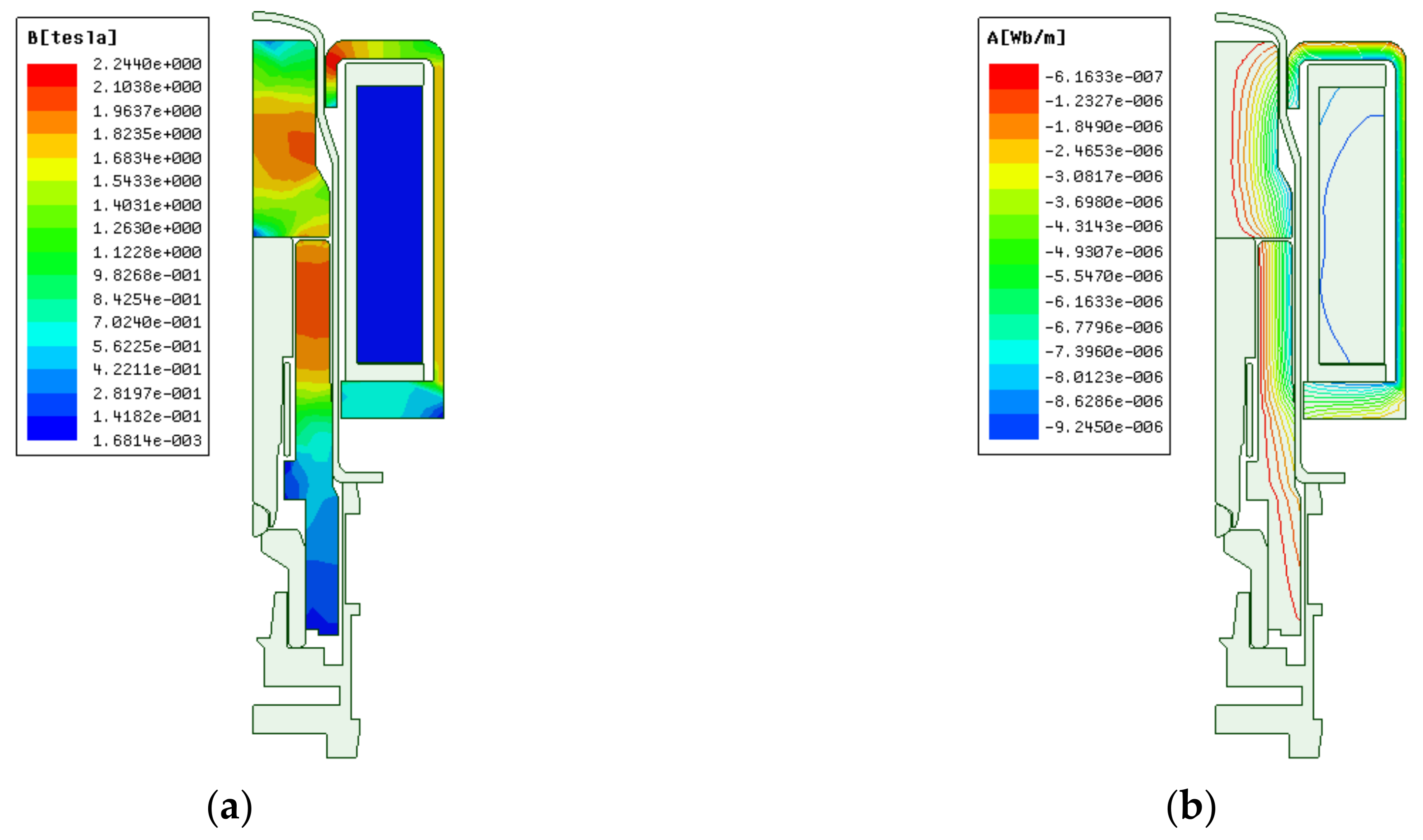
Permanent magnet polarity direction and specifications were set through simulation. The TCV was designed by applying the set permanent magnet, and as a result of simulation analysis, the total electromagnetic force required for the TCV was satisfied. The total electromagnetic force showed similar results in simulation and product evaluation.
(2)
When a current of 3.4 A was applied, the total electromagnetic force of the permanent magnet TCV at 0.30 mm and 0 mm strokes was similar to that of the conventional TCV. These results show that there is no problem with the operation of the armature by total electromagnetic force when a current of 3.4 A is applied in each stroke. Therefore, there was no problem with the total electromagnetic force of TCV even if we replaced the low case with an N-50H permanent magnet in the conventional TCV.
(3)
Even after cutting off the current at the 0 mm stroke, which is the position where the sol-seat flow path is completely closed, a magnetic force of 7.3 N remains due to the permanent magnet. It was possible to close the flow path of the sol-seat and cut off the current for the time required to be maintained, and only the magnetic force of the permanent magnet could be used. Therefore, it was possible to reduce the temperature rise and power consumption of the magnetic coil.
(4)
A reverse current of −0.9 to −2.0 A was required to open the closed flow path of the sol-seat. It has the same function as power off in a conventional TCV. Thus, the permanent magnet solenoid valve was able to open the flow path with a reverse current and shut off the current (0 A) after the flow path was opened.
(5)
After the flow path of the sol-seat was completely opened (0.30 mm stroke), the magnetic force by the permanent magnet was about 2.75 N. However, there was no problem with the TCV function as there was not enough force to move the armature.
In future research, we plan to study not only TCV for ESC, but also various vehicle solenoid valves as permanent magnet solenoid valves. We want to obtain technology that can reduce energy consumption by designing and verifying various permanent magnets using computer-aided engineering.

5. Patents

“SOLENOID VALVE FOR ELECTRONIC STABILITY CONTROL” Patent application number Korea: 10-2020-0150286.

Author Contributions

Conceptualization, H.-S.L. and Y.-S.K.; investigation, S.-G.P., H.-J.L. and M.-P.H.; data curation, H.-S.L., S.-G.P., H.-J.L. and M.-P.H.; writing—original draft preparation, H.-S.L.; writing—review and editing, Y.-S.K.; supervision, Y.-S.K. All authors have read and agreed to the published version of the manuscript.

Funding

This study was conducted under a purchase-linked project for small and medium-sized commercialization technology development and purchased conditional new technology development of the Ministry of SMEs and Startups. We thank the Ministry of SMEs and Startups for their support (S2860926). In addition, the support of the Korea Institute of Industrial Technology as “Development of intelligent root technology with add-on modules (KITECH EO-21-0009)”.

Institutional Review Board Statement

Not applicable.

Informed Consent Statement

Not applicable.

Data Availability Statement

Not applicable.

Acknowledgments

The authors would like to thank those associated with the co-research organizations (erae Automotive Systems Co., Ltd. in Korea and Korea Institute of Industrial Technology in Korea).

Conflicts of Interest

The authors declare no conflict of interest.

References

  1. Chan, C.C. An overview of electric vehicle technology. Proc. IEEE 1993, 81, 1202–1213. [Google Scholar] [CrossRef]
  2. Jalil, N.; Kheir, N.A.; Salman, M. A rule-based energy management strategy for a series hybrid vehicle. In Proceedings of the 1997 American Control Conference, Albuquerque, NM, USA, 4–6 June 1997; pp. 689–693. [Google Scholar]
  3. Kutkut, N.H.; Wiegman, H.L.; Divan, D.M.; Novotny, D.W. Design considerations for charge equalization of an electric vehicle battery system. IEEE Trans. Ind. Appl. 1999, 35, 28–35. [Google Scholar] [CrossRef] [Green Version]
  4. Rodatz, P.; Paganelli, G.; Sciarretta, A.; Guzzella, L. Optimal power management of an experimental fuel cell/supercapacitor-powered hybrid vehicle. Control. Eng. Pract. 2005, 13, 41–53. [Google Scholar] [CrossRef]
  5. Chen, Q.; Shu, H.; Chen, L. Simulation analysis of cogging torque of permanent magnet synchronous motor for electric vehicle. J. Mech. Sci. Technol. 2012, 26, 4065–4071. [Google Scholar] [CrossRef]
  6. Do, H.T.; Ahn, K.K. Velocity control of a secondary controlled closed-loop hydrostatic transmission system using an adaptive fuzzy sliding mode controller. J. Mech. Sci. Technol. 2013, 27, 875–884. [Google Scholar] [CrossRef]
  7. Johannesson, L.; Asbogard, M.; Egardt, B. Assessing the Potential of Predictive Control for Hybrid Vehicle Powertrains Using Stochastic Dynamic Programming. IEEE Trans. Intell. Transp. Syst. 2007, 8, 71–83. [Google Scholar] [CrossRef]
  8. Wellstead, P.; Pettit, N. Analysis and redesign of an antilock brake system controller. IEE Proc. Control Theory Appl. 1997, 144, 413–426. [Google Scholar] [CrossRef]
  9. Gerum, E.; Palkovics, L.; Semsey, A. Roll-Over Prevention System for Commercial Vehicles ? Additional Sensorless Function of the Electronic Brake System. Veh. Syst. Dyn. 1999, 32, 285–297. [Google Scholar] [CrossRef]
  10. Margolis, D.; Shim, T. A bond graph model incorporating sensors, actuators, and vehicle dynamics for developing controllers for vehicle safety. J. Frankl. Inst. 2001, 338, 21–34. [Google Scholar] [CrossRef]
  11. Trivedi, M.M.; Gandhi, T.; McCall, J. Looking-In and Looking-Out of a Vehicle: Computer-Vision-Based Enhanced Vehicle Safety. IEEE Trans. Intell. Transp. Syst. 2007, 8, 108–120. [Google Scholar] [CrossRef] [Green Version]
  12. Bera, T.; Bhattacharya, K.; Samantaray, A. Evaluation of antilock braking system with an integrated model of full vehicle system dynamics. Simul. Model. Pr. Theory 2011, 19, 2131–2150. [Google Scholar] [CrossRef]
  13. Chung, W.S.; Song, H.S.; Jung, D.H.; Park, T.W. Development of a systematic process for hydraulic brake system design and for hot judder characteristic estimation. J. Mech. Sci. Technol. 2012, 26, 3893–3901. [Google Scholar] [CrossRef]
  14. Liebemann, E.; Meder, K.; Schuh, J.; Nenninger, G. Safety and Performance Enhancement: The Bosch Electronic Stability Control (ESP); Robert Bosch GmbH: Gerlingen, Germany, 2004. [Google Scholar]
  15. Kim, H.M.; Kang, I.-H.; Choi, K.-S.; Wang, H.-M.; Tae, H.-J. Computational Analysis of Pressure Control Characteristics in a VFS Solenoid Valve; Inje University: Gimhae, Korea, 2007. [Google Scholar] [CrossRef]
  16. Kim, N.; Kim, K.; Lee, W.; Hwang, I. Development of Mando ESP (Electronic Stability Program); Mando Corporation: Seongnam-si, Korea, 2003. [Google Scholar] [CrossRef]
  17. Sung, B.J. A design of on/off type solenoid actuator for valve operation. J. Drive Control 2009, 6, 24–32. [Google Scholar]
  18. Wu, S.; Zhao, X.; Li, C.; Jiao, Z.; Qu, F. Multiobjective Optimization of a Hollow Plunger Type Solenoid for High Speed On/Off Valve. IEEE Trans. Ind. Electron. 2018, 65, 3115–3124. [Google Scholar] [CrossRef]
  19. Branciforte, M.; Meli, A.; Muscato, G.; Porto, D. ANN and Non-Integer Order Modeling of ABS Solenoid Valves. IEEE Trans. Control. Syst. Technol. 2011, 19, 628–635. [Google Scholar] [CrossRef]
  20. Yun, S.; Yun, D. Performance improvement strategy of solenoid valve and magnetic material technique. J. Drive Control 2009, 6, 28–34. [Google Scholar]
  21. Yun, S.N.; Ham, Y.B.; Park, J.H. A Study on Response Improvement of a Proportional Solenoid Actuator. J. Drive Control 2016, 13, 47–52. [Google Scholar] [CrossRef] [Green Version]
  22. Yun, S. Design of Proportional Solenoid Actuator using Maxwell CAE Software. J. Drive Control 2012, 9, 32–36. [Google Scholar] [CrossRef]
  23. Tanaka, H. Proportional Solenoid. Fluid Power Syst. 2000, 31, 200–207. [Google Scholar]
  24. Lee, H.R.; Ahn, J.H.; Shin, J.O.; Kim, H.Y. Design of Solenoid Actuator for FCV Cylinder Valve Considering Structural Safety. J. Korean Soc. Manuf. Technol. Eng. 2016, 25, 157–163. [Google Scholar] [CrossRef] [Green Version]
  25. Liu, Q.; Bo, H.; Qin, B. Experimental study and numerical analysis on electromagnetic force of direct action solenoid valve. Nucl. Eng. Des. 2010, 240, 4031–4036. [Google Scholar] [CrossRef]
  26. Sun, Z.Y.; Li, G.X.; Wang, L.; Wang, W.H.; Gao, Q.X.; Wang, J. Effects of structure parameters on the static electromagnetic characteristics of solenoid valve for an electronic unit pump. Energy Convers. Manag. 2016, 113, 119–130. [Google Scholar] [CrossRef]
  27. Hung, N.B.; Lim, O. Improvement of Electromagnetic Force and Dynamic Response of a Solenoid Injector Based on the Effects of Key Parameters. Int. J. Automot. Technol. 2019, 20, 949–960. [Google Scholar] [CrossRef]
  28. Tao, G.; Chen, H.Y.; J, Y.Y.; He, Z. Optimal design of the magnetic field of a high-speed response solenoid valve. J. Mater. Process. Technol. 2002, 129, 555–558. [Google Scholar] [CrossRef]
  29. Bayat, F.; Tehrani, F.; Danesh, M. Finite element analysis of proportional solenoid characteristics in hydraulic valves. Int. J. Automot. Technol. 2012, 13, 809–816. [Google Scholar] [CrossRef]
  30. Wang, L.; Li, G.-X.; Xu, C.-L.; Xi, X.; Wu, X.-J.; Sun, S.-P. Effect of characteristic parameters on the magnetic properties of solenoid valve for high-pressure common rail diesel engine. Energy Convers. Manag. 2016, 127, 656–666. [Google Scholar] [CrossRef]
  31. Sung, B.J.; Lee, E.W.; Kim, H.E. Empirical Design of an On and Off Type Solenoid Actuator for Valve Operation. KIEE Int. Trans. Electr. Mach. Energy Convers. Syst. 2004, 4, 39–46. [Google Scholar]
Figure 1. Configuration of the ESC: (a) Structure of ESC; (b) Solenoid valves of the ESC.
Applsci 11 07794 g001
Figure 2. Comparison of the conventional TCV and permanent magnet TCV operation methods: (a) Conventional TCV operation method; (b) Permanent magnet TCV operation method.
Applsci 11 07794 g002
Figure 3. Schematic of the conventional TCV.
Applsci 11 07794 g003
Figure 4. Air gap between the armature and magnet core: (a) Sol-seat flow path open; (b) Sol-seat flow path close.
Applsci 11 07794 g004
Figure 5. Load distribution of TCV.
Applsci 11 07794 g005
Figure 6. Schematic of the permanent magnet TCV.
Applsci 11 07794 g006
Figure 8. Polarity direction of the permanent magnet.
Applsci 11 07794 g008
Figure 9. Total electromagnetic force according to the polarity direction of the permanent magnet.
Applsci 11 07794 g009
Figure 10. Design of the permanent magnet.
Applsci 11 07794 g010
Figure 11. Total electromagnetic force for the permanent magnet specification: (a) total electromagnetic force for each stroke at 3.4 A; (b) total electromagnetic force for each stroke at 0 A.
Applsci 11 07794 g011
Figure 12. Conventional TCV: (a) magnetic flux density at 3.4 A; (b) magnetic field strength at 3.4 A.
Applsci 11 07794 g012
Figure 13. Electromagnetic force for each stroke in the conventional TCV.
Applsci 11 07794 g013
Figure 17. Manufacture of the permanent magnet TCV: (a) magnet coil winding; (b) permanent magnetic; (c) coil assembly; (d) TCV.
Applsci 11 07794 g017
Figure 18. Magnet force tester of TCV.
Applsci 11 07794 g018
Figure 19. Comparison of FEA and experiment results: (a) 0 mm stroke; (b) 0.3 mm stroke.
Applsci 11 07794 g019
Figure 20. Function tester of TCV.
Applsci 11 07794 g020
Figure 21. Comparisons of function tester results: (a) conventional TCV; (b) permanent magnet TCV.
Applsci 11 07794 g021
Table 1. Design parameters of the magnetic coil winding.
ParameterValues
Voltage (V)12
Resistance (Ohm)3.5
Conduct diameter (Cd:Φ)0.3
Overall diameter (Nd:Φ)0.345
Bobbin inner diameter (Bi:Φ)8.5
Bobbin outer diameter (Bo:Φ)16.1
Bobbin height (h:mm)12.8
Bobbin width (w:mm)3.3
Specific resistance (Ohm-mm)1.7E−0.5
Resistance per unit length (Ohm-mm)2.44E−0.4
Layer (turns)36.5
Step10
Magnetic coil turns360
Ampere turn1234
Table 2. Design parameters of the permanent magnet.
ParameterValues
N-35HResidual induction (T)1.16–1.22
Coercive force (KA/m)845 MIN
N-42HResidual induction (T)1.28–1.34
Coercive force (KA/m)938 MIN
N-48HResidual induction (T)1.36–1.43
Coercive force (KA/m)1000 MIN
N-50HResidual induction (T)1.39–1.46
Coercive force (KA/m)1035 MIN
Air gap (mm)0.47
Stroke (mm)0.30
Publisher’s Note: MDPI stays neutral with regard to jurisdictional claims in published maps and institutional affiliations.

