Article

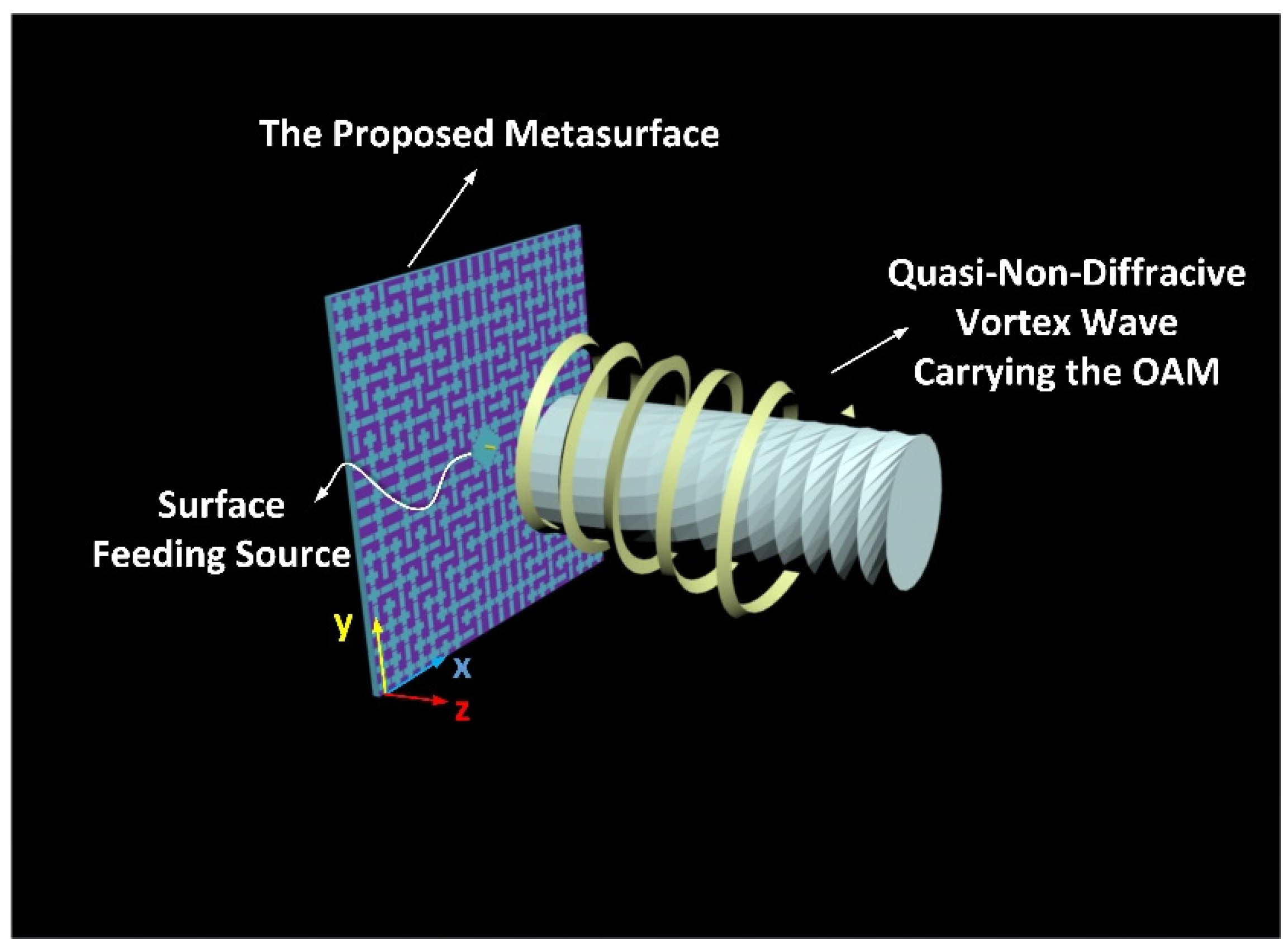
Generation of Circularly Polarized Quasi-Non-Diffractive Vortex Wave via a Microwave Holographic Metasurface Integrated with a Monopole

1
The State Key Laboratory of Information Photonics and Optical Communications, Beijing University of Posts and Telecommunications, Beijing 100876, China
2
Beijing Key Laboratory of Network System Architecture and Convergence, Beijing Laboratory of Advanced Information Networks, Beijing University of Posts and Telecommunications, Beijing 100876, China
*
Authors to whom correspondence should be addressed.
Appl. Sci. 2021, 11(15), 7128; https://doi.org/10.3390/app11157128
Submission received: 29 June 2021 / Revised: 25 July 2021 / Accepted: 30 July 2021 / Published: 2 August 2021
(This article belongs to the Section Applied Physics General)

Abstract

:
In this paper, a novel method for generating a circularly polarized (CP) quasi-non-diffractive vortex wave carrying orbital angular momentum (OAM), based on the microwave holographic metasurface integrated with a monopole, is proposed. This method is the combination of the non-diffraction theory and the principle of waveguide-fed-based holography and is equivalent to a superposition of two scalar impedance modulation surfaces. To verify the proposed method, a holographic metasurface generating a left-handed circularly polarized (LHCP) quasi-non-diffractive vortex wave carrying −1 mode OAM at the normal direction, was simulated and analyzed. The metasurface consisted of inhomogeneous slot units on a grounded substrate and a monopole excitation. Moreover, the location distribution of slots was determined by a computed interferogram between the reference wave and the object wave with the non-diffractive feature. Compared with an ordinary vortex wave, the quasi-non-diffractive wave obtained by our proposed method possessed a smaller divergence radius and a stronger electric field strength in the 9 times wavelength range. It paved a new path for manipulating the non-diffractive vortex wave in medium distance without using an external feeding source, which holds great potential for the miniaturization devices applied in medium-distance high-capacity secure communication, high-resolution imaging and intelligent detection.

1. Introduction

The vortex waves with orbital angular momentum, known to have the potential for increasing the capacity of a channel largely due to their infinite species of orthogonal topological modes, have attracted tremendous interest from different fields in recent years. However, the vortex wave communication is highly limited in realistic applications due to its inherent character of divergence in the propagation path. Attributed to the diffraction extension of an electromagnetic wave, the radius of a vortex wave increased gradually with increasing propagation distance; the impact for microwave regime is severer than optical frequencies. To resolve the problem of serious divergence, researchers started to introduce the non-diffractive characteristic to the generation method of vortex waves, enabling the restriction of diffraction extension within the predesigned diffraction-free range. As one of the non-diffractive waves, the Bessel beam with the features of non-diffracting, self-healing and controllable convergence angle, has been investigated widely. Due to the fact that a Bessel beam carrying unlimited energy is theoretically created by an infinitely large aperture, the practical Bessel beam created by a limited size aperture is a quasi-non-diffractive Bessel beam. Combining the characteristics of the quasi-non-diffraction transmission and the spiral wavefront, a quasi-non-diffractive vortex wave which possesses almost constant energy can be achieved, which has great potential in the applications of short- to medium-range high-capacity communications, as well as vortex-wave-based high-resolution imaging and detection.
Since the vortex wave carrying orbital angular momentum [1] was first provided and defined by Allen in 1992, various approaches of generating and steering vortex waves were widely studied, including the spiral phase plates (SPPs) [2], patch arrays [3], lens [4], computer-generated holograms [5], graphene devices [6], components with vanadium dioxide [7] and reflect/transmit metasurfaces [8,9,10,11,12]. Due to the advantages of the accurate and flexible manipulation of electromagnetic waves, the metasurfaces [13], as the 2D equivalent ultra-thin metamaterials, have gradually become one of the most effective means for controlling electromagnetic waves. Recently, Yang et al. proposed an envelope-modulation theory-based scheme as a novel route to engineer shaped–tailored metasurfaces [14] for manipulating the orbital angular momentum spectrum in a wide microwave bandwidth, further promoting the broadband of OAM-based applications. They also proposed an ultrawideband single-layer metasurface to generate integer and fractional orbital angular momentum, the generated vortex waves covering the 105% relative bandwidth [15]. Lv et al. proposed a low-profile transmitting metasurface using the dimension extension approach to achieve linearly polarized vortex waves in Ku-band [16], which facilitated the vortex wave-based communication applications. Although these OAM modulators exhibited powerful control on the amplitude, phase and polarization of the spiral waves, the problems of the beam divergence were not considered and well addressed. The diameter of a vortex wave increases gradually as the propagation distance becomes longer, which may have caused the misidentification of the topological modes for the receiving end with a small aperture.
To resolve the problem of divergence, the quasi-non-diffractive feature was introduced to the design methods of vortex waves for improving convergence and energy efficiency. Zhang et al. firstly proposed two kinds of phase-engineered metalens [17], by introducing the phase profiles of focus and Bessel beams into the Pancharatnam-Berry (P-B) based metasurfaces; converging and non-diffraction vortex beams with small converging angles are achieved, respectively. In order to reduce the design complexity of the metasurface, they also proposed a 1-bit non-diffractive microwave vortex beam generator [18], which greatly reduced the types of desired phase units. Based on geometric optics and projection methodologies, two kinds of 3-D printed terahertz discrete dielectric lenses [19] were proposed by Wu et al. to produce non-diffractive high-order vortex beams in the terahertz regime, offering a new approach for the THz ultra-high-speed communications. Liu et al. proposed a reflective metasurface launching multiple pseudo-Bessel beams with high efficiency [20], by which the energy of the beams was preserved as almost constant along the propagation axes. The non-diffractive vortex-wave metasurfaces mentioned above provided profound insights into the generation methodologies; however, they were excited by the externally spatial feeding sources, which occupied large spaces and caused the spatial feed error. To improve these issues, a tensor impedance modulation-based metasurface integrated with a feeding source was proposed by Meng et al. [21], which reduced the space-occupied volume greatly and provided efficient control for the high-order Bessel vortex beams. However, due to the requirement of different rotation angles and the size of the gap in each unit, it was challenging to realize a reconfigurable metasurface which could dynamically steer the non-diffractive waves in the future. Smith et al. proposed a waveguide-fed structure-based holography [22] to construct metasurfaces, which manipulated the radiated beams flexibly by the interference between the surface wave and the predesigned interferogram. Only by changing the on/off states of unit cells that coupled to the continuous guide-mode of magnetic components, could the interferogram with different features be created and the metasurface radiate an expected object wave. This phase-keying holographic method has potential advantages in dynamically reconfigurable metasurfaces and intelligent sensors. It has been applied to the realization of polarized waves [23], multi-beam [24], focus [25], imaging [26] and intelligent sensing [27]. However, the manipulation of the circularly polarized non-diffractive vortex waves carrying OAM has not been researched before.
In this work, we propose an innovative methodology for generating a CP quasi-non-diffractive vortex wave with the desired OAM mode by combining non-diffracting theory and the principle of waveguide-fed-based holography. The general forms of the designing formulas were derived to validate our proposal. A metasurface generating an LHCP quasi-diffraction-free vortex wave carrying an l = −1 OAM mode was constructed, simulated and analyzed in the electromagnetic software. The numerical simulations demonstrated that the LHCP quasi-non-diffractive vortex wave possessed an almost constant divergence radius and electric field strength in the 9 times wavelength range compared with a conventional vortex wave. It provided a new way to generate and steer the CP quasi-non-diffractive vortex wave in medium-distance without using an external excitation, which held enormous potential for the miniaturization devices applied in wireless energy transmission and high-capacity communication.

2. Design Principle and Procedure

2.1. Design Principle

In this research, a monopole-integrated holographic metasurface generating a circularly polarized quasi-non-diffractive vortex wave carrying the desired OAM mode, is proposed. The proposed metasurface consists of a back-grounded substrate covered by inhomogeneous slot units and a monopole as the surface feeding source. The upper conductor layer and the bottom grounded layer form a parallel-plate waveguide, supporting the surface wave produced from the feeding source, propagated as a cylindrical wave in the cavity. When the surface wave, viewed as the reference wave, interacts with the slot units arranged according to the interferogram, an expected object wave can be recovered and radiated into the air, as depicted in Figure 1.
As an important part of the holography, the analytical forms of the object wave first need to be decided. Herein, a quasi-non-diffractive vortex wave is the object wave, which has the character of adjustably converging radii and a controllable depth-of-field. Owing to the non-diffracting and self-healing properties [28], the Bessel beam is deeply investigated and used to alleviate the problem of diffraction. As a special solution of the Helmholtz homogenous wave equation in the cylindrical system, the intensity transverse profile of a Bessel beam is independent of distance and fits to the Bessel function [29]. The idea that a Bessel beam carrying the infinite energy is produced by an infinite large aperture, is impractical and cannot be realized. In practice, we only can use the aperture with a finite size to generate a Bessel beam characterized by quasi-non-diffraction within the specialized range. Introducing the non-diffractive feature of the zeroth-order Bessel beam into the vortex wave will create a high-order quasi-Bessel vortex wave.
Currently, there are mainly two methods to achieve the quasi-Bessel beam: one method is to steer the wavefront of the incident wave by using lens-like devices [17,30,31,32]; the second method is dependent on the inward cylindrical travelling wave aperture [21,33,34,35]. Herein, our proposed method is similar to a combination of the two methods; an equivalent axicon-based method is adopted to analytically express the object wave while waveguide-fed-based holography is applied to realize the radiation. By superposing the phase profile of the Bessel beam and the vortex wave, a quasi-non-diffractive vortex wave in the controllable propagation direction of ( θ , φ ) can be generated and its phase profile Φ ( x , y ) can be expressed as follows:
Φ ( x , y ) = l p h i k [ sin β x 2 + y 2 + ( x s i n θ cos φ + y s i n θ s i n φ ) ] ,
where l is the topological charge, p h i is the azimuth angle, and k denotes the wavenumber in the air space. The β is the base angle of the equivalent axicon and its value should not be less than the minimum allowed in the non-diffracting condition. The ( x , y ) and ( θ , φ ) represent the surface coordinate positions of each cell and the radiation angle, respectively.
Due to the fact that an interferogram is the interference result of a reference wave and an object wave, its pattern is closely related to the polarization, amplitude and wavefront of two waves. For the generation of a circularly polarized wave, we proposed a method [36] by superposing x- and y-polarized holograms independently. Combining this method and the phase profile of the quasi-non-diffractive vortex wave obtained from Equation (1), the analytical expression of a required object wave P C P B O A M can be expressed as follows:
P C P B O A M = P o b j x + P o b j y = A 0 e j Φ ( x , y ) ( x ^ + j y ^ ) ,
where A 0 denotes the amplitude of the wave and is set as the value of 1 here. P o b j x and P o b j y respectively denotes x- and y-polarized object waves, and x ^ and y ^ represent x- and y-polarized unit vectors, respectively. As for another essential parameter of the holographic metasurface, the reference wave H r e f , a surface wave with the cylindrical wavefront excited by the monopole, can be analytically expressed by the Hankel function [24] as follows:
H r e f = H r e f x + H r e f y = H 0 ( 1 ) ( k g r ) sin φ x ^ + H 0 ( 1 ) ( k g r ) c o s φ y ^
where k g denotes the wave number in the dielectric, φ represents the azimuthal angle of any location on the metasurface, r is the radial distance from the origin. H r e f x and H r e f y are the x- and y-components of the reference magnetic field, respectively.
After the object wave and the reference wave are determined, the phase holograms of two linearly polarized waves can be calculated based on the interference principle as follows:
p h a s e y p o l = a n g l e ( M y ) = a n g l e ( P o b j y H r e f x * )   p h a s e x p o l = a n g l e ( M x ) = a n g l e ( P o b j x H r e f y * ) ,
where p h a s e y p o l and p h a s e x p o l are the y- and x-polarized phase hologram distribution, respectively. M y and M x denote two linearly polarized interference results, i.e., y- and x-polarized holograms. It is noting that P o b j y , P o b j x , H r e f x and H r e f y are the corresponding scalar parameters. The * denotes the conjugation of complex parameters and a n g l e ( ) denotes the operation of computing the complex phase angle.
For determining the slot-type distribution of each linearly polarized hologram, a binary judging criterion was adopted. If the absolute value of its holographic phase ( | p h a s e ( x , y ) | ) was smaller than the predefined threshold, a slot unit was set up. Similarly, if this condition was not satisfied, none of the slots were needed to be created in this unit. Following this guideline, two slot-type patterns generating x- and y-polarized quasi-non-diffractive vortex waves can be obtained, respectively. Due to the fact that a circularly polarized wave is composed of two orthogonal polarized waves with a phase difference of 90°, the final slot-type pattern is achieved by superposing two linearly polarized slot-type patterns; four types of the slot are available: none, horizontal-, vertical- and cross-slot.

2.2. Design Procedure

In order to provide designers with profound insights into our proposal, the design process of the holographic source-integrated metasurface is summarized as follows.
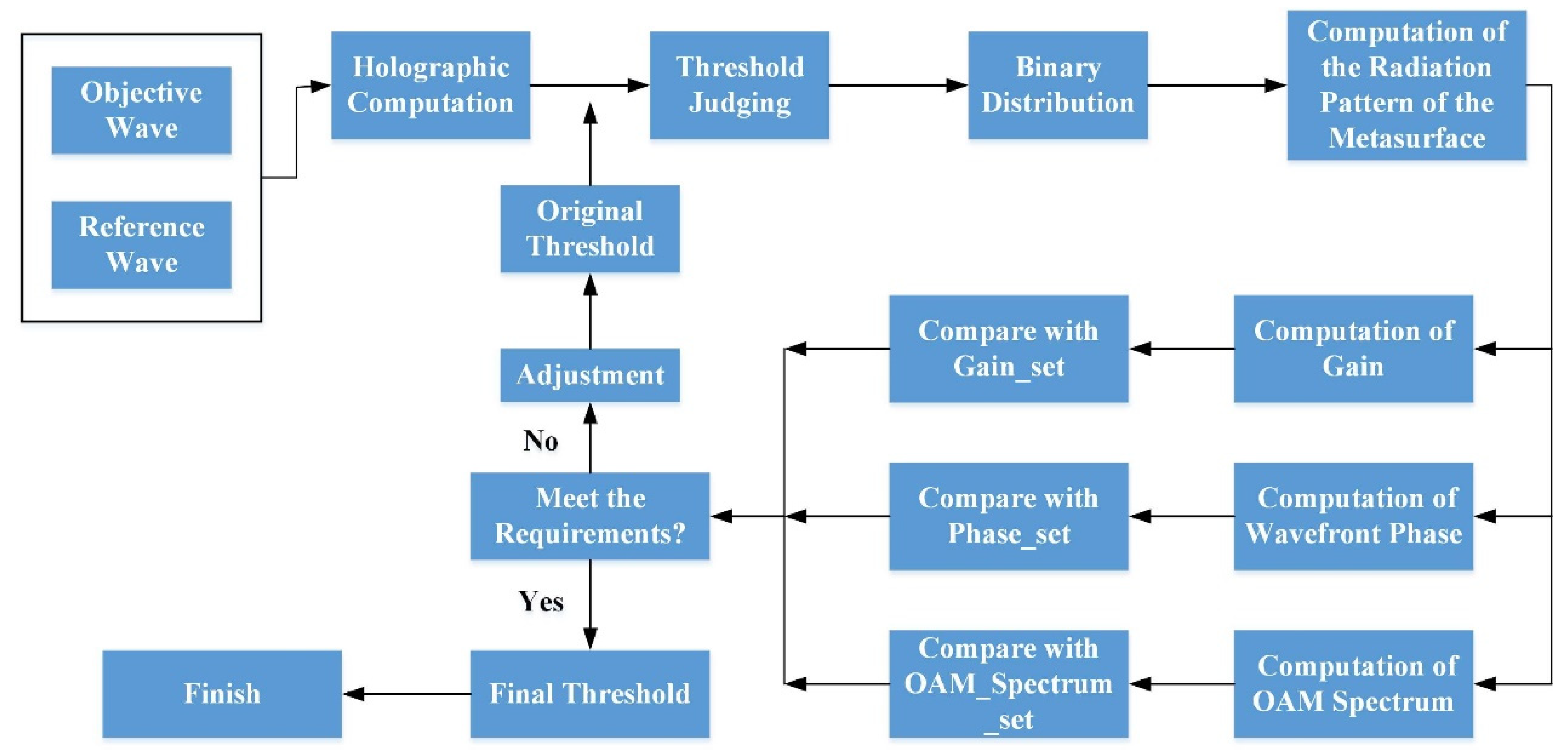
  • First of all, the required parameters should be decided before the holographic calculation, including operation frequency (f), size of the aperture (D), depth-of-field of the non-diffracting beam ( Z max ), the base angle of the equivalent ( β ), topological charge (l) and polarization.
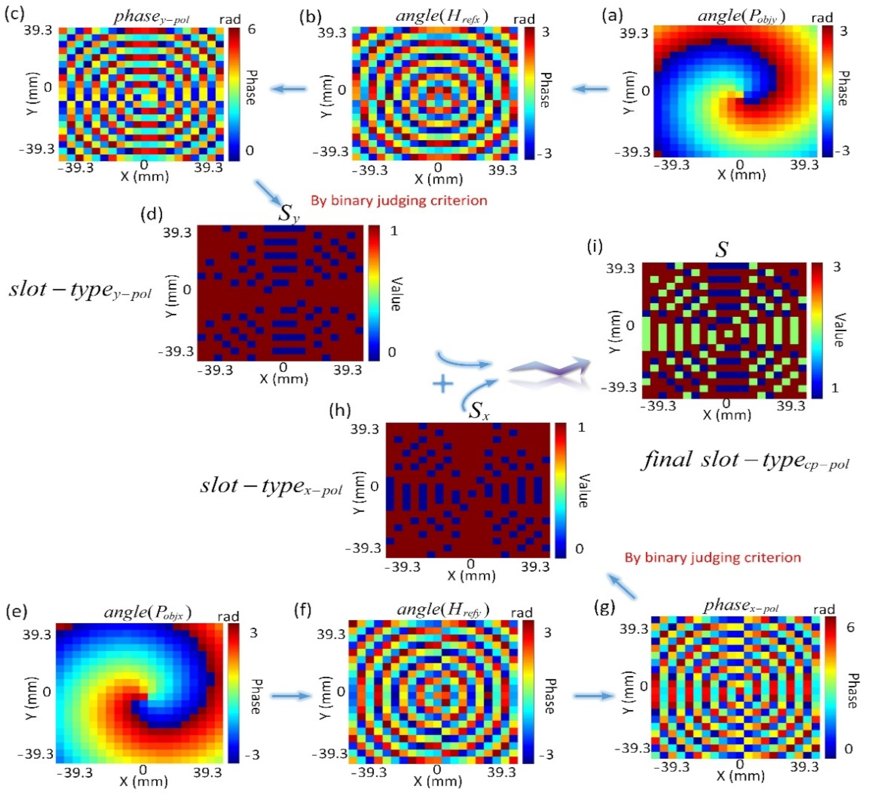
  • Afterward, according to the selected parameters, the desired object wave P C P B O A M and the reference wave H r e f were expressed analytically. The former was related to the charactersitics of the radiated beam, while the latter was associated with the type and location of the feeding source.
    In the next part, we calculated two linearly polarized holograms ( M y and M x ) and obtained their phase hologram distribution ( p h a s e y p o l and p h a s e x p o l ).
  • After that, we normalized the holographic phase distribution to the same range and defined the judging threshold ( θ t ). Following the binary judging criterion, we obtained the slot-type distribution patterns ( S y and S x ) generated by two linearly polarized object waves ( P o b j y and P o b j x ).
  • In the end, we superposed the slot-type distribution patterns ( S y and S x ) generated by two linearly polarized object waves to obtain the final slot-type pattern ( S ) of the circularly polarized quasi-non-diffractive vortex wave. According to the resulting slot-type pattern, a metasurface with the capability of steering the circularly polarized quasi-non-diffractive vortex wave can be established finally.

3. Modeling, Simulation and Analysis

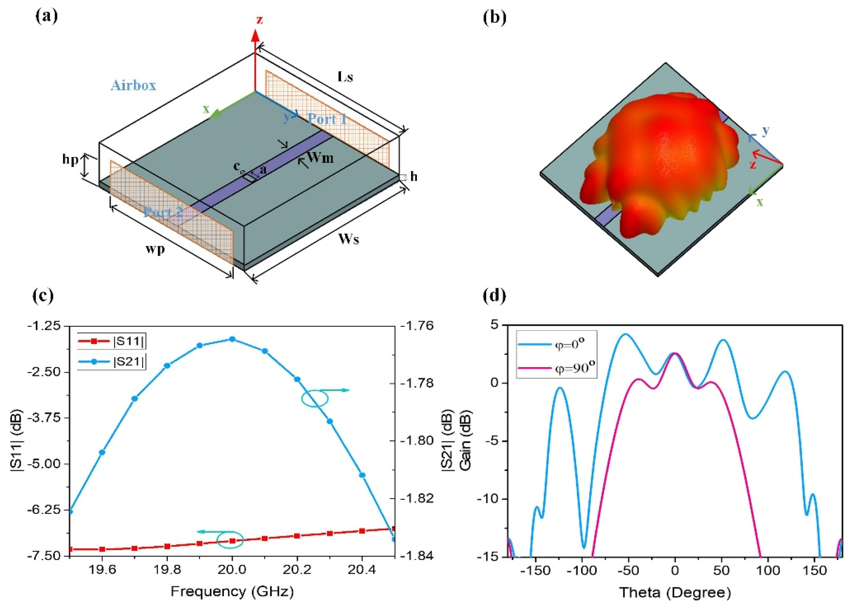
3.1. Modelling and Simulation of the Unit Cell

As the basic elements of the proposed metasurface, a rectangular slot is adopted to couple with the travelling magnetic field energy in the cavity and radiates one polarized component of the objective waves. A horizontal slot along the x-axis radiates a y-polarized wave, accordingly, a vertical slot radiates the x-polarized wave. By assembling two kinds of units, the circularly polarized waves can be generated and steered flexibly. Thus, the modelling and simulation of the single unit is of significance and needs to be studied first.
The radiation feature of a single slot unit can be studied by a microstrip transmission line mimicking a surface wave excitation. By analyzing the results of scatter parameters and radiation patterns, the original size of a slot unit can be decided. In Figure 2a, an electromagnetic simulation model of a slot unit is built up, in which a slot along the y-axis is patterned in the top layer of the transmission line. This model is composed of a grounded substrate with a size of ( L s = 49.7 mm ∗ W s = 46.15 mm ∗ h = 1.542 mm) and a microstrip with a width of W m = 3.55 mm. An air box is built up and two wave-ports are created on its outside surfaces. The size of the wave-port is ( W p = 11 W m h p = 6 h ) and the thickness of the ground is t = 0.035 mm. The model of a microstrip transmission line patterned in a slot unit performs a full-wave simulation in the ANSYS Electromagnetics Suite software. For the simulation, a radiation boundary is applied to the air box with a size of ( L s W s ∗ 8 h ) to mimic an infinitely large free space. As the input port, port 1 is excited by the source with a power of 1 W and port 2 is set as the output port. By using the full-wave simulation, the reflection coefficient | S 11 | and the transmission coefficient | S 21 | of this model can be obtained. The former ( | S 11 | ) denotes the ratio of reflection power to the input power of port 1, while the latter ( | S 21 | ) represents the ratio of output power of port 2 to the input power of port 1. As shown in Figure 2c, | S 11 | remains below –6 dB during the operation band and | S 21 | is below −1.2 dB during the same bandwidth, demonstrating that most of the energy is converted into radiation. The 3D radiation pattern of the unit model and 2D radiation patterns at the planes of φ = 0° and φ = 90° are illustrated in Figure 2b,d, respectively, the maximum total gain of which is 2.6 dB.

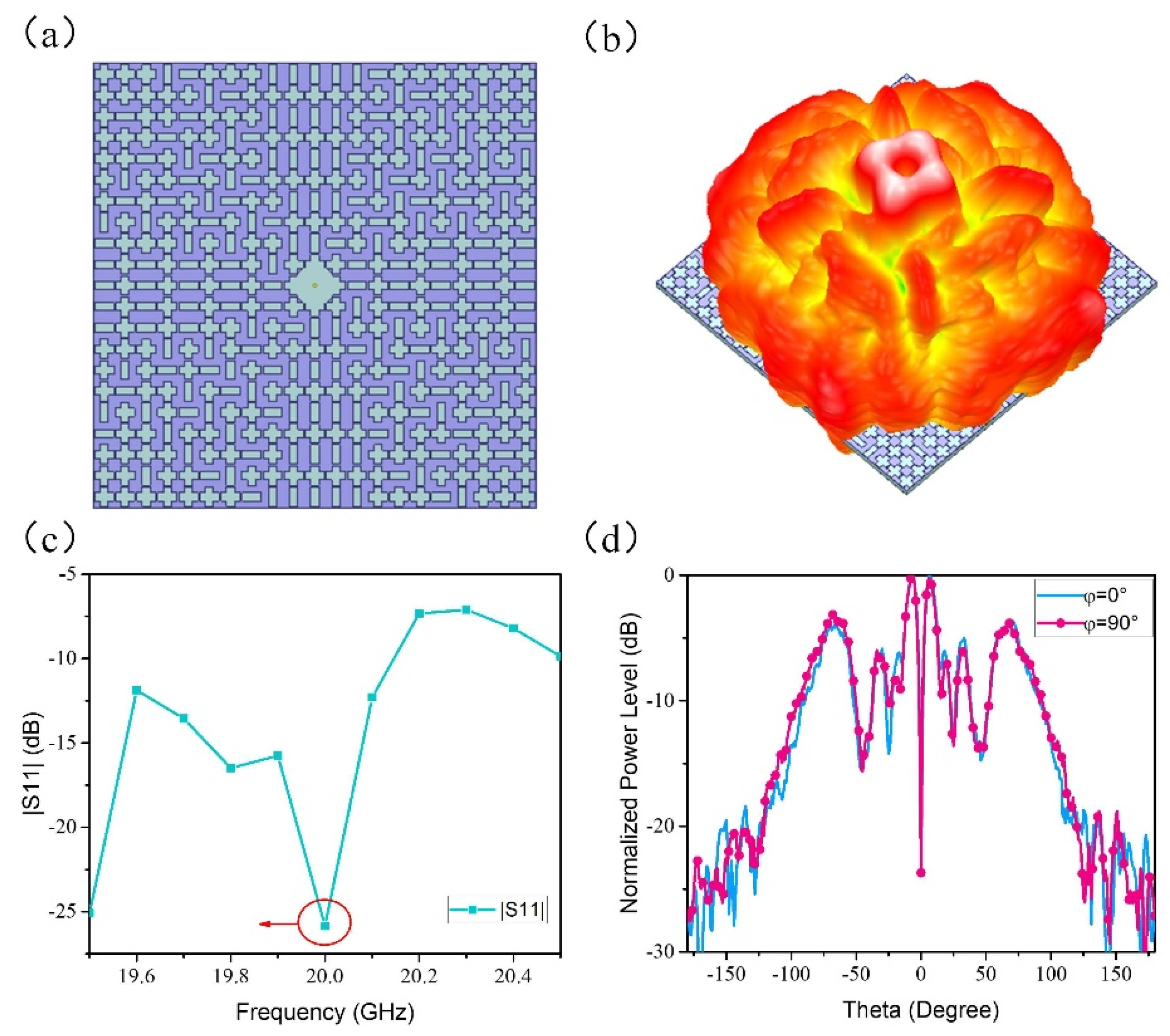
3.2. Modelling and Simulation of the Metasurface
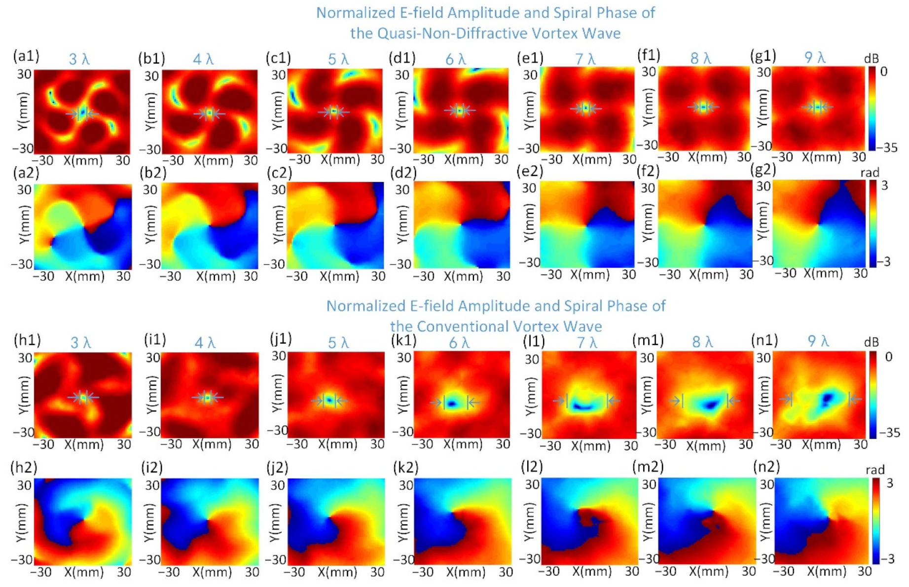
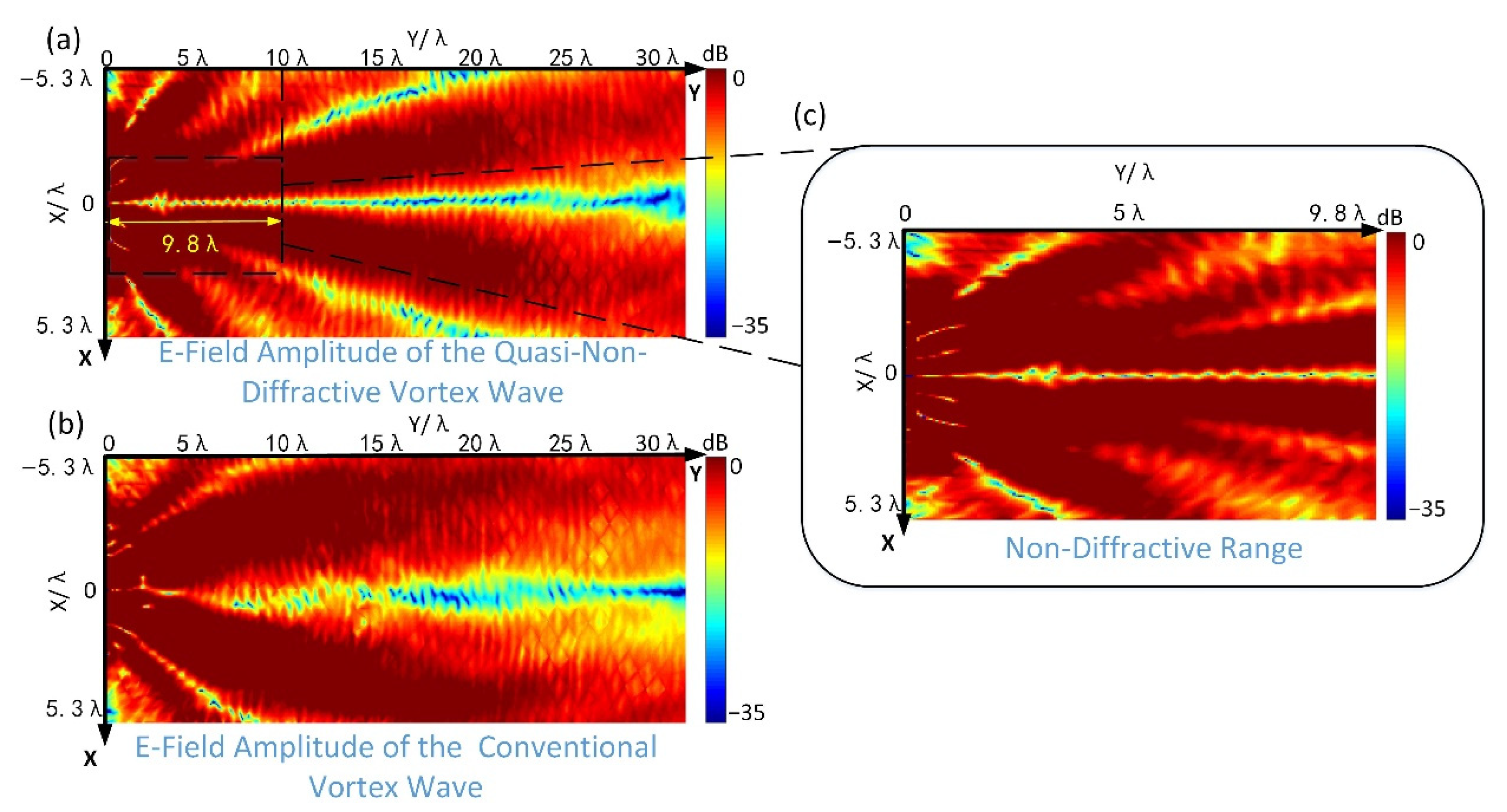
Once the size of slot units and characteristic parameters of the object wave are determined, a metasurface generating a circularly polarized quasi-non-diffractive vortex wave can be created. Herein, we construct a metasurface radiating a left-handed circularly polarized (LHCP) quasi-non-diffracting vortex wave carrying l = −1 mode OAM in 20 GHz. The base angle ( β ) of the equivalent axicon is specified as 15° and the aperture ( D ) of the metasurface is 78.75 mm as a result, which codetermines the largest non-diffractive distance, i.e., Z max = D / ( 2 t a n β ) = 146.95 mm. Each row of the proposed metasurface with square size contains 21 slot units, the period of which is set as p = 3.75 mm.
The scheme of the calculation process of the final slot-type distribution pattern is illustrated in Figure 3. Following the design procedure, substituting the related parameters into the Equations (1)–(3), the phase profiles of two linearly polarized object waves ( P o b j y , P o b j x ) and reference waves ( H r e f x , H r e f y ) can first be computed. Afterward, based on the holographic interference principle, two interference phase profiles ( p h a s e y p o l , p h a s e x p o l ), calculated by linearly polarized waves, can be obtained by using Equation (4). By applying the binary judging method with a fixed threshold to two interference phase profiles, respectively, their corresponding single slot-type distribution patterns are achieved. The y-polarized slot-type pattern contains two kinds of states including the no-slot and the horizontal slot, which denote “00” and “01” in binary way, respectively. Similarly, the x-polarized slot-type pattern also has two states referring to the no-slot and the vertical slot, which denote “00” and “10”, respectively. Finally, by superposing each binary value of the two linearly polarized slot-type distribution patterns ( S y , S x ) directly, a final slot-type distribution pattern ( S ) can be conveniently achieved. This pattern contains four kinds of values ranging from 0 to 3, which denotes no-slot, horizontal, vertical and cross-type slot units, respectively.
Herein, the threshold is preliminary determined by the numerical optimization with the help of Matlab and its calculation process (refer to Figure 4). Firstly, the holographic computation is performed by using the objective wave and reference wave, and the interference phase distribution on the metasurface is obtained. Secondly, the interference phase distribution is compared with the initial threshold by binary algorithm to obtain the slot distribution. Afterward, combined with the phase distribution and binary slot distribution of the metasurface, the radiation characteristics of the metasurface can be computed, including gain, wavefront phase and OAM spectrum. Next, the three calculated results are compared with the desired target values (Gain_ set, Phase_ set and OAM_ Spectrum_set). If the requirements are not met, the original threshold is adjusted and recalculate from the second step. If the requirements are satisfied, the process is complete and the current threshold is determined as the final value. Since computation causes a lack of consideration of coupling between the units, it is essential to conduct the joint computation and simulation between the Matlab and ANSYS software. By using the simulated E-field data to revise the threshold further, a suitable threshold can be decided. After the optimization, the threshold is selected as 288° (i.e., the normalized value is 0.8 relative to 360°), which is optimal for our proposal. Due to the final slot-type distribution pattern, a model of the metasurface generating a CP quasi-non-diffractive vortex wave carrying l = −1 mode OAM can be built accurately.
The threshold is important for designing metasurfaces, so it is necessary to analyze how it affects the performance of the metasurface. According to the holographic principle, the designed metasurface is equivalent to a hologram containing the interference information of a reference wave and an objective wave, and can also be regarded as the absolute value of the phase difference between the two waves, which is consistent with the principle of impedance modulation. Therefore, the threshold represents the deviation between the sampled reference wave phase and the desired objective wave phase. If the deviation is too small, only less energy can be collected from the slots, resulting in a poor beamforming at the far-field. On the contrary, when the deviation is too large, many redundant slots are set in many unnecessary places, and the radiated energy interferes with the objective beam and deteriorates the wavefront phase. The selection range and sensitivity of the threshold are also related to the type and characteristics of the objective wave. For example, when the objective wave is a plane wave, the optional range of the threshold is narrow, usually in the range of 60–110°. Moreover, the sensitivity of the hypersurface to the threshold change is about 10°. When the expected wave becomes a quasi-non-diffractive vortex wave, the optimal variation range is extended to a range from 60–300° and the sensitivity is changed to 36°. This is because the vortex wave is a hollow beam and possesses a spiral phase profile. The complex radiation characteristics increase the demand for energy.
An expected metasurface is created in the ANSYS Electromagnetics Suite according to a one-to-one mapping relationship between the numerical values and the types of slots. In Figure 5a, a top view of the proposed metasurface is presented, which is composed of 440 inhomogeneous slot units and a monopole as the central feeding source. Full-wave simulation is performed, far-field radiation patterns and scattering parameters of the proposed metasurface are obtained and illustrated in Figure 5b–d. It can be seen from Figure 5c that, for the most part, the reflection coefficient ( | S 11 | ) remains below −10 dB from 19.5 GHz to 20.5 GHz, especially at −26 dB at the central frequency of 20 GHz, exhibiting a good impedance matching. The 3D far-field radiation pattern of the quasi-non-diffractive wave is a hollow beam with a small diverging radius, as depicted in Figure 5b. In addition, its normalized power levels on the planes of φ = 0° and φ = 90° are illustrated in Figure 5d. There is a null existing in the main lobe of the 2D radiation pattern, demonstrating that a vortex wave with OAM is produced in the normal direction. Moreover, because it is not in the non-diffracting superposition zone, the side lobes are relatively high, which is in accordance with the theory of quasi-non-diffraction. The simulation results demonstrate that the proposed holographic generator of a quasi-non-diffractive vortex wave possesses a good performance in the far-field radiation.
For illustrating the quasi-non-diffractive feature of the vortex wave generated from the proposed metasurface, the normalized electric-field (E-field) amplitude and spiral phase distributions of the LHCP components on the different x–y cross-sections, located at the height range 3 λ to 9 λ , are calculated and depicted in Figure 6(a1–g2) due to the maximum non-diffracting distance of Z max = 146.95 mm (i.e., 9.8 λ ). The normalized E-field amplitude distribution of a quasi-non-diffractive vortex wave is still a doughnut-shaped zone, and a null zone is located in the center of the energy distribution. In Figure 6(a1–g1), the divergence radius of the null zone of the vortex wave is about 5 mm (0.33 λ ), 2 mm (0.13 λ ), 3 mm (0.2 λ ), 3.35 mm (0.22 λ ), 4 mm (0.27 λ ) and 4.3 mm (0.29 λ ), respectively, which almost remains stable within the 9 λ range. Due to the formation of a non-diffractive wave which is superposed by forward and backward waves, the non-diffracting feature becomes constant from the Z max /2, which results in the divergence radius of 3 λ , slightly larger than the other values. In addition, the outer radius of the E-field amplitude distribution enlarges slowly and does not cover the x–y cross-section, with a radius of 60 mm, until the vortex wave propagates at a distance of 9 λ away from the metasurface. During this progress, most of the energy is highly concentrated around the propagating axis.
In order to demonstrate the effect of diffraction suppression clearly, a holographic metasurface generating a conventional vortex wave carrying the same topological charge is designed as a reference of comparison. The normalized E-field amplitudes and the spiral phase distributions are presented in Figure 6(h1–n2). As shown in these figures, the divergence radius of the null zone of the vortex wave is close to 2.5 mm (0.17 λ ), 3.1 mm (0.21 λ ), 5 mm (0.33 λ ), 10 mm (0.67 λ ), 14 mm (0.93 λ ) and 17 mm (1.13 λ ), respectively, which shows a more obvious trend of divergence than a non-diffractive case in the specified range. In addition, the intensity of the energy around the center is more divergent than the vortex wave characterized with the non-diffraction feature. The spiral phase patterns of two kinds of vortex waves are also illustrated in Figure 6(a2–g2) and (h2–n2), respectively. The variation of the phase within one cycle is 360° clockwise, which demonstrates the spirally topological mode is −1. Moreover, the intrinsic properties of a vortex wave are not influenced by the introduction of the diffraction feature. Furthermore, to compare the divergence trend out of the maximum non-diffractive range, simulated results of the normalized E-field amplitude and spiral phase distributions from 10 λ to 30 λ are also illustrated in Figure 7. As for the quasi-non-diffractive vortex wave, the divergence radii of the null zone (approximately 11 mm, 17 mm, 20 mm, 22 mm and 36 mm, respectively) enlarge slowly and maintain a relatively concentrated energy envelope. In contrast, the divergence radii of the null zone of the vortex wave are approximately 10 mm, 17 mm, 23 mm, 30 mm and 51 mm, respectively, which shows a more serious trend of divergence than a non-diffractive case in the specified range. The simulated results are consistent with the hypothesis that, although located at the area outside of the non-diffracting distance, the divergence trend of the quasi-non-diffractive vortex wave is always weaker than the conventional vortex wave [17].
The simulated distributions of the E-field amplitude on the x–z planes for the quasi-non-diffractive and conventional vortex waves are plotted in Figure 8, respectively. As for the quasi-non-diffractive vortex wave in the x–z cross-section, the distance between the two main lobes of the divergence beams maintains a value of 0.6 λ (9 mm) within the non-diffractive range. As a contrast, the distance between the two main lobes of a conventional vortex wave is already 3.47 λ (52 mm) at the distance of 9.8 λ (146.95 mm) away from the metasurface, which exhibits a faster divergence rate than the former. It can be seen from the comparison that the divergence property of the vortex wave is significantly suppressed in the non-diffractive distance.

4. Discussion

Through observing the E-field amplitude distributions and spiral phase patterns on the x–y planes, the OAM mode of the vortex wave is verified. To evaluate the purity of desired topological mode further, the normalized OAM spectrum from the x–y plane at the height of 9 λ is calculated by using the Fourier transform method [37], as shown in Figure 9a. It is shown that the spectrum with l = −1 mode accounts for a major part of the wave and other OAM spectrum components are below 0.1, demonstrating that the generated quasi-non-diffractive vortex wave possesses a high mode purity. The transmission efficiencies of the quasi-non-diffractive and conventional OAM waves are computed and depicted in Figure 9b, respectively. Here, the transmission efficiency is defined as the ratio of the power flow through an observational plane in the simulated environment to the counterpart on the metasurface. As evident from Figure 9b, the transmission efficiency of a conventional OAM wave exhibits a rapidly declining trend as the propagation distance increases, while the declining rate of a quasi-non-diffractive case is slower than the former and almost remains at a constant value. In addition, the farther the propagation distance, the more obvious the difference of the efficiency.
As for the fabrication and the experimental setting, some factors also need to be considered. Firstly, using our proposed method, the desired metasurface can be fabricated by the printed circuit board (PCB) or 3D printing processing technology; the advantages of easy fabrication and low cost will facilitate it to be widely applied in many fields. Secondly, the machining accuracy of the slot units on the fabricated metasurface is of importance; if the machining accuracy of the edge length is too low, it will lead to a serious deviation of the central resonant frequency. For the case of extremely small side length, researchers should use high-precision micromachining technology to ensure the radiation performance of the designed metasurface. Thirdly, because a monopole, as the feed, is integrated on to the holographic metasurface, the impedance matching of the port needs to be considered. If a monopole is directly placed on the top of a conductor layer of the metasurface to excite the units, the interaction between the surface wave around the coaxial inner conductor and the surrounding metal will worsen the port matching. Therefore, it is necessary to dig an annular gap around the inner conductor, which is equivalent to a capacitive matching ring to improve matching of the port. Here, we set a ring with an outer diameter of 3.72 mm to achieve a good impedance matching.
Lastly, in the simulation, we set observation planes at different heights above the metasurface to achieve the E-field amplitude distribution. However, for the actual measurement, a set of near-field scanning equipment is needed to test the E-field distribution on different cross sections. Generally, a near-field probe is controlled to scan on the required cross sections and sample the E-field data at constant interval. The smaller the sampling interval, the more time and resources it takes, and the researcher should find a balance.

5. Conclusions

In summary, a novel method is proposed, based on the superposition of non-diffracting phase profiles and holograms, with two linearly polarized components generating a circularly polarized quasi-non-diffractive vortex wave carrying the orbital angular momentum. Our proposed method is similar to the combination of an equivalent axicon-based method and waveguide-fed-based holography; the former is adopted to analytically express the object wave while the latter is applied to realize the radiation. Only by changing the on/off states of unit cells that couple to the continuous guide-mode magnetic components, can the interferogram with different features be created and an expected object wave can subsequently be generated. This method can be viewed as one of the digital phase-keying holographic methods, and this is a notable feature compared with other kinds of holographic metasurfaces.
Based on this method, a holographic metasurface integrated with a surface feeding source is simulated and analyzed, which produces an LHCP quasi-non-diffractive vortex wave with l = −1 mode in the normal direction. The simulation results demonstrate the effective diffraction suppression and a concentrative energy distribution within 9 λ distance away from the metasurface, compared with a pure vortex wave. Furthermore, to compare the divergence trend out of the maximum non-diffractive range, results of the normalized E-field amplitude and spiral phase distributions from 10 λ to 30 λ , are simulated. The numerical simulations demonstrate that the LHCP quasi-non-diffractive vortex wave possesses an almost constant divergence radius and electric field strength in the 30 times wavelength range compared with a conventional vortex wave. By this calculation, OAM purity and the transmission efficiency of the generated quasi-non-diffractive wave are analyzed in detail. As for the fabrication and experiment considerations, four factors including the processing technology, machining accuracy, impedance matching and near-field measurement are discussed comprehensively in this paper.
The proposed designing method is equivalent to a linear superposition of two scalar impedance modulation surfaces, which provide a more flexible manipulation and lower design complexity than a method of tensor impedance modulation. It paves a new way for generating and controlling the CP quasi-non-diffractive vortex wave in short- or medium-distance, which holds great potential for miniaturization devices applied in wireless energy transmission, high-resolution imaging and intelligent detection. Moreover, this phase-keying holographic method facilitates designing dynamically reconfigurable metasurfaces and intelligent devices in future.

Author Contributions

Conceptualization, C.Z.; methodology, C.Z.; software, C.Z. and L.W.; validation, C.Z.; formal analysis, C.Z.; investigation, C.Z.; resources, C.Z.; data curation, C.Z.; writing—original draft preparation, C.Z.; writing—review and editing, C.Z.; visualization, C.Z.; supervision, L.D., X.C. and S.L.; project administration, L.D. and S.L.; funding acquisition, S.L. All authors have read and agreed to the published version of the manuscript.

Funding

This research was funded by 111 project (NO. B17007), National Natural Science Foundation of China (NO. 61427801 and NO. 61601040), Beijing Science and Technology Plan Project (No. Z191100002019015).

Institutional Review Board Statement

Not applicable.

Informed Consent Statement

Not applicable.

Data Availability Statement

Not applicable.

Conflicts of Interest

The authors declare no conflict of interest.

References

  1. Allen, L.; Beijersbergen, M.W.; Spreeuw, R.; Woerdman, J.P. Orbital angular momentum of light and the transformation of Laguerre-Gaussian laser modes. Phys. Rev. A. 2016, 45, 8185–8189. [Google Scholar] [CrossRef]
  2. Oemrawsingh, S.S.R.; van Houwelingen, J.A.W.; Eliel, E.R.; Woerdman, E.J.; Verstegen, K.; Kloosterboer, J.G.; Hooft, G.W. Production and characterization of spiral phase plates for optical wavelengths. Appl. Optics. 2004, 43, 688–694. [Google Scholar] [CrossRef] [PubMed]
  3. Zhang, D.; He, C.; Chen, Q.; Liu, J.; Hong, L. Converged OAM vortex wave generation using EBG-loaded patch array antenna. Int. J. RF Microw. Comput. Aided Eng. 2021, 31, e22711. [Google Scholar] [CrossRef]
  4. Liu, T.; Feng, R.; Yi, J.; Burokur, S.N.; Mao, C.; Zhang, H.; Werner, D.H. All-dielectric transformation medium mimicking a broadband converging lens. Opt. Express. 2018, 26, 20331–20341. [Google Scholar] [CrossRef] [PubMed]
  5. Amini, A.; Oraizi, H. Adiabatic Floquet-wave expansion for the analysis of leaky-wave holograms generating polarized vortex beams. Phys. Rev. Appl. 2021, 15, 034049. [Google Scholar] [CrossRef]
  6. Rouhi, K.; Rajabalipanah, H.; Abdolali, A. Multi-bit graphene-based bias-encoded metasurfaces for real-time terahertz wavefront shaping: From controllable orbital angular momentum generation toward arbitrary beam tailoring. Carbon 2019, 149, 125–138. [Google Scholar] [CrossRef]
  7. Hu, F.; Guo, W.; Rong, Q.; Zhang, L.; Zhou, Y. Electrically controlled terahertz binary coder based on hysteresis of vanadium dioxide embedded modulator. J. Lightwave Technol. 2021, 39, 2476–2481. [Google Scholar] [CrossRef]
  8. Bai, X.; Kong, F.; Sun, Y.; Wang, G.; Qian, J.; Li, X.; Cao, A.; He, C.; Liang, X.; Jin, R.; et al. High-efficiency transmissive programmable metasurface for multimode OAM generation. Adv. Optical. Mater. 2020, 8, 2000570. [Google Scholar] [CrossRef]
  9. Ma, L.; Chen, C.; Zhou, L.; Jiang, S.; Zhang, H. Single-layer transmissive metasurface for generating OAM vortex wave with homogeneous radiation based on the principle of Fabry-Perot cavity. Appl. Phys. Lett. 2019, 114, 81603. [Google Scholar] [CrossRef]
  10. Zhang, S.; Huo, P.; Zhu, W.; Zhang, C.; Chen, P.; Liu, M.; Chen, L.; Lezec, H.J.; Agrawal, A.; Lu, Y.; et al. Broadband detection of multiple spin and orbital angular momenta via dielectric metasurface. Laser Photonics Rev. 2020, 14, 2000062. [Google Scholar] [CrossRef]
  11. Luo, Z.; Wang, Q.; Zhang, X.G.; Wu, J.W.; Dai, J.Y.; Zhang, L.; Wu, H.T.; Zhang, H.C.; Ma, H.F.; Cheng, Q.; et al. Digital nonlinear metasurfaces: Intensity-dependent metasurface with digitally reconfigurable distribution of nonlinearity. Adv. Optical Mater. 2019, 7, 1900792. [Google Scholar] [CrossRef]
  12. Luo, Z.; Ren, X.; Wang, Q.; Cheng, Q.; Cui, T.J. Anisotropic and Nonlinear Metasurface for Multiple Functions. Sci. China Inf. Sci. 2021, 1–10. [Google Scholar] [CrossRef]
  13. Yu, N.; Genevet, P.; Kats, M.A.; Aieta, F.; Tetienne, J.-P.; Capasso, F.; Gaburro, Z. Light propagation with phase discontinuities reflection and refraction. Science 2011, 334, 333–337. [Google Scholar] [CrossRef] [PubMed] [Green Version]
  14. Yang, L.-J.; Sun, S.; Sha, W.E.I. Manipulation of orbital angular momentum spectrum using shape-tailored metasurfaces. Adv. Optical Mater. 2021, 9, 2001711. [Google Scholar] [CrossRef]
  15. Yang, L.-J.; Sun, S.; Sha, W.E.I. Ultra-wideband reflection-type metasurface for generating integer and fractional orbital angular momentum. IEEE Trans. Antennas Propag. 2020, 68, 2166–2175. [Google Scholar] [CrossRef] [Green Version]
  16. Lv, H.H.; Huang, Q.-L.; Yi, X.-J.; Hou, J.-Q.; Shi, X.-W. Low-profile transmitting metasurface using single dielectric substrate for OAM generation. IEEE Antennas Wirel. Propag. Lett. 2020, 19, 881–885. [Google Scholar] [CrossRef]
  17. Zhang, K.; Yuan, Y.; Zhang, D.; Ding, X.; Ratni, B.; Burokur, S.N.; Lu, M.; Tang, K.; Wu, Q. Phase-engineered metalenses to generate converging and non-diffractive vortex beam carrying orbital angular momentum in microwave region. Opt. Express. 2018, 26, 1351–1360. [Google Scholar] [CrossRef]
  18. Wang, Y.; Zhang, K.; Yuan, Y.; Ding, X.; Yang, G.; Fu, J.; Wu, Q.; Guan, C. 1-bit non-diffractive vortex beam generator based on FSS in microwave region. IEEE Trans. Magn. 2021, 57, 4001504. [Google Scholar] [CrossRef]
  19. Wu, G.B.; Chan, K.F.; Chan, C.H. 3-D printed terahertz lens to generate higher-order Bessel beams carrying OAM. IEEE Trans. Antennas Propag. 2020, 69, 3399–3480. [Google Scholar] [CrossRef]
  20. Liu, H.; Xue, H.; Liu, Y.; Li, L. Generation of multiple pseudo Bessel beams with accurately controllable propagation directions and high efficiency using a reflective metasurface. Appl. Sci. 2020, 10, 7219. [Google Scholar] [CrossRef]
  21. Meng, X.; Chen, X.; Yang, L.; Xue, W.; Zhang, A.; Sha, W.E.I.; Cheng, Q. Launcher of high-order Bessel vortex beam carrying orbital angular momentum by designing anisotropic holographic metasurface. Appl. Phys. Lett. 2020, 117, 243503. [Google Scholar] [CrossRef]
  22. Smith, D.R.; Yurduseven, O.; Mancera, L.P.; Bowen, P. Analysis of a waveguide-fed metasurface antenna. Phys. Rev. Appl. 2017, 8, 054048. [Google Scholar] [CrossRef] [Green Version]
  23. Yurduseven, O.; Smith, D.R. Dual-Polarization Printed Holographic Multibeam Metasurface Antenna. IEEE Antennas Wirel. Propag. Lett. 2017, 16, 2738–2741. [Google Scholar] [CrossRef]
  24. Yurduseven, O.; Lee, C.; David, G.-O.; Ettorre, M.; Sauleau, R.; Chattopadhyay, G.; Fusco, V.; Chahat, N. MultiBeam Si/GaAs holographic metasurface antenna at W-band. IEEE Trans. Antennas Propag. 2020, 69, 3523–3528. [Google Scholar] [CrossRef]
  25. Yurduseven, O.; Marks, D.L.; Gollub, J.N.; Smith, D.R. Design and analysis of a reconfigurable holographic metasurface aperture for dynamic focusing in the Fresnel zone. IEEE Access. 2017, 5, 15055–15065. [Google Scholar] [CrossRef]
  26. Imani, M.F.; Gollub, J.N.; Yurduseven, O.; Diebold, A.V.; Smith, D.R. Review of metasurface antennas for computational microwave imaging. IEEE Trans. Antennas Propag. 2020, 68, 1860–1875. [Google Scholar] [CrossRef] [Green Version]
  27. Hougne, P.D.; Imani, M.F.; Diebold, A.V.; Horstmeyer, R.; Smith, D.R. Learned integrated sensing pipeline: Reconfigurable metasurface transceivers as trainable physical layer in an artificial neural network. Adv. Sci. 2020, 7, 1901913. [Google Scholar] [CrossRef] [Green Version]
  28. Durnin, J. Exact solutions for nondiffracting beams. I. The scalar theory. J. Opt. Soc. 1987, 4, 651–654. [Google Scholar] [CrossRef]
  29. Durnin, J.; Miceli, J.J.; Eberly, J.H. Diffraction-free beams. Phys. Rev. Lett. 1987, 58, 1499–1501. [Google Scholar] [CrossRef]
  30. Meng, Y.; Yi, J.; Burokur, S.N.; Kang, L.; Zhang, H.; Werner, D.H. Phase-modulation based transmitarray convergence lens for vortex wave carrying orbital angular momentum. Opt. Express 2018, 26, 22019–22029. [Google Scholar] [CrossRef]
  31. Zhong, Y.C.; Cheng, Y.J. Generating and steering quasi-non-diffractive beam by near-field planar risley prisms. IEEE Trans. Antennas Propag. 2020, 68, 7767–7776. [Google Scholar] [CrossRef]
  32. Zhong, Y.C.; Cheng, Y.J. Ka-band wideband large depth-of-field beam generation through a phase shifting surface antenna. IEEE Trans. Antennas Propag. 2016, 64, 5038–5045. [Google Scholar] [CrossRef]
  33. Cai, B.G.; Li, Y.B.; Jiang, W.X.; Cheng, Q.; Cui, T.J. Generation of spatial Bessel beams using holographic metasurface. Opt. Express. 2015, 23, 7593–7601. [Google Scholar] [CrossRef]
  34. Ettorre, M.; Pavone, S.C.; Casaletti, M.; Albani, M. Experimental validation of Bessel beam generation using an inward Hankel aperture distribution. IEEE Trans. Antennas Propag. 2015, 63, 2539–2544. [Google Scholar] [CrossRef] [Green Version]
  35. Wu, Y.F.; Cheng, Y.J. Generating and 2-D steering large depth-of-field beam by leaky-wave antenna array with a modified parabolic reflector. IEEE Trans. Antennas Propag. 2020, 68, 2779–2787. [Google Scholar] [CrossRef]
  36. Zhang, C.; Deng, L.; Zhu, J.; Hong, W.; Wang, L.; Wang, H.; Zeng, T.; Ren, X.; He, X.; Zhao, Z.; et al. A right-handed circularly polarized wave generated by a waveguide-fed holographic metasurface. J. Phys. D Appl. Phys. 2020, 53, 26LT01. [Google Scholar] [CrossRef]
  37. Strain, M.J.; Cai, X.; Wang, J.; Zhu, J.; Phillips, D.B.; Chen, L.; Lopez- Garcia, M.L.; O’Brien, J.; Thompson, M.G.; Sorel, M.; et al. Fast electrical switching of orbital angular momentum modes using ultra-compact integrated vortex emitters. Nat. Commun. 2014, 5, 4856. [Google Scholar] [CrossRef] [Green Version]
Figure 1. Scheme of a monopole-integrated holographic metasurface generating a quasi-non-diffractive vortex wave carrying the desired OAM mode.
Applsci 11 07128 g001
Figure 2. The model and simulation results. (a) The simulation model of a slot unit; (b) 3D radiation pattern of the unit model. (c) Scattering parameters ( | S 11 | , | S 21 | ) of the model; (d) The simulated far-field radiation patterns of the unit cell on the planes of φ = 0° and φ = 90°, respectively.
Applsci 11 07128 g002
Figure 3. Scheme of the calculation process of the final slot-type distribution pattern. Phase distribution patterns of the (a,e) object waves, (b,f) reference waves, and (c,g) inferograms with the y- and x-polarization, respectively. Slot-type distribution patterns of the (d) y-, (h) x- and (i) left-handed circularly polarized quasi-non-vortex waves, respectively.
Applsci 11 07128 g003
Figure 4. Calculation flow chart for determining the threshold.
Applsci 11 07128 g004
Figure 5. The simulated model of the proposed metasurface and its simulation results of radiation characteristics. (a) Top view of the proposed metasurface; (b) 3D radiation pattern; (c) reflection coefficient | S 11 | ; (d) and normalized power levels at planes of φ = 0° and φ = 90°, respectively.
Applsci 11 07128 g005
Figure 6. Comparison between the quasi-non-diffractive and conventional vortex waves. The (a1g1) normalized E-field amplitude and (a2g2) spiral phase of the quasi-non-diffractive vortex wave. The (h1n1) normalized E-field amplitude and (h2n2) spiral phase of the conventional vortex wave.
Applsci 11 07128 g006
Figure 7. The (a1e1) normalized E-field amplitude and (a2e2) spiral phase distributions of the quasi-non-diffractive vortex wave generated from the proposed metasurface at a height of 10 λ , 15 λ , 20 λ , 25 λ and 30 λ above the metasurface, respectively, where λ is 15 mm. Similarly, the (f1j1) normalized E-field amplitude and (f2j2) spiral phase distributions of the conventional vortex wave are shown.
Applsci 11 07128 g007
Figure 8. Simulated distributions of the E-field amplitude on the x–z planes for (a) the quasi-non-diffractive vortex wave and (b) conventional vortex wave, respectively. (c) A magnified view of the non-diffractive range.
Applsci 11 07128 g008
Figure 9. The (a) normalized OAM spectrum of the vortex wave carrying l = −1 mode OAM and (b) transmission efficiency of the quasi-non-diffractive and conventional OAM waves.
Applsci 11 07128 g009
Publisher’s Note: MDPI stays neutral with regard to jurisdictional claims in published maps and institutional affiliations.

