Article

Multi-Link Magnet Device with Electromagnetic Manipulation System for Assisting Finger Movements with Wireless Operation

1
Department of Electronics Convergence Engineering, Wonkwang University, 460 Iksandae-ro, Iksan 54538, Korea
2
Department of Rehabilitation Medicine, School of Medicine, Wonkwang University, 460 Iksandae-ro, Iksan 54538, Korea
3
Wonkwang Institute of Materials Science and Technology, Wonkwang University, 460 Iksandae-ro, Iksan 54538, Korea
*
Authors to whom correspondence should be addressed.
Appl. Sci. 2021, 11(15), 6762; https://doi.org/10.3390/app11156762
Submission received: 22 June 2021 / Revised: 16 July 2021 / Accepted: 21 July 2021 / Published: 23 July 2021
(This article belongs to the Section Electrical, Electronics and Communications Engineering)

Abstract

:
We introduce a new mechanism and control system for wireless assistive finger training. The proposed mechanism and control system can provide natural finger flexion and extension via magnetic force and torque between a driving coil and a multi-link magnetic assist device placed on the fingers. The proposed mechanism is designed to allow normal movement while maintaining a natural finger shape, even when multiple magnets are applied to the fingers. Anatomical features were considered in the design to accommodate the angular changes between the fingers during hand extension and flexion. The magnetic force between the control system and the device on the hand allows extension and flexion of the fingers without the use of wires and electrical motors. The performance of the driving system and the magnetic device were verified through various simulations and experiments. A control program with motion tracking is also developed using LabView software. Hence, a wireless assistive finger training system is successfully realized.

1. Introduction

Hand injury is one of the major symptoms of strokes and, in post-stroke care, rehabilitation training is the most important treatment for significant improvement in the patient’s condition [1,2,3]. Various assistive devices or systems, which can be classified as active or passive, have been developed for application to hand rehabilitation. As regards active devices, many stroke patients cannot freely perform finger movements and, therefore, most assistive devices apply external forces on the patient’s fingers. To date, various mechanisms for external force generation have been developed and applied, such as those employed in robot hands [4,5,6,7,8]. In general, mechanical devices for hand training have the advantage of generating relatively large forces because of their configuration components, such as electrical motors, wires, and mechanical elements. However, these devices also have various disadvantages, such as complex mechanical structures, large volumes, limited degrees of freedom (DOFs), and poor wearability on the hand [9,10,11,12,13,14]. To avoid these problems, soft-actuator-based training devices have been developed [15,16,17,18], wherein the soft-actuators are arranged in relatively simple configuration and are controlled by pneumatics [19]. However, their control method or control system is complex. As regards passive training devices, flexible gloves are one example [20,21]. Patients wear the gloves to train their hands using computer graphics or a virtual reality system (VR), with no external force [22,23,24]. Therefore, passive devices are inapplicable to patients who cannot move their hands independently. A rehabilitation device that can detect the finger position using an EMG sensor and generate an external force at the same time has been developed [25,26]. However, poor usability still remains a problem to be solved.
To solve these problems, we propose a new method and mechanism for wireless active finger training or rehabilitation, which uses magnetic forces and is based on wireless operation. In our previous study, we realized a wireless driving method involving magnets applied to the fingers [27]. However, because of magnetic interaction force between the magnets on the fingers, the four fingers (excluding the thumb) could not be trained simultaneously [28]. Thus, in this study, we present a new magnetic device for installation on the fingers. The developed device has various advantages, e.g., a simple structure and configuration (minimized mechanical element), high DOF, and good wearability. In particular, the proposed mechanism and configuration allow both active and passive actuations. The developed system consists of a multi-link magnetic assist device for finger flexion and extension, assistive magnet array in the driving coil and on the palm, and a coil-based control system (bipolar controller, DC power supply, cooling system, and 3-DOF armrest). For motion control, we employ a newly developed vision-based motion tracking system using LabView software (Austin, TX, USA).
The developed multi-link magnetic assist device is comprised of permanent magnets, bearings, and links, and must prevent strong attractive or repulsive force between the permanent magnets to achieve extension and flexion movements. Assistive magnet arrays in the coil and on the palm enhance extension and flexion, respectively. A vision-based motion tracking program is developed, and motion analysis is performed to verify assistive finger movement achieved via the magnetic force. Hence, the proposed method and system are verified. Section 2 mainly deals with the mechanism and operation principle of the proposed device, the control method, and the analysis of the drive system. In Section 3, the proposed method was verified by analyzing the relationship between the hand trajectory according to the change in current and the change in force and hand angle. In Section 4, the main characteristics are reviewed, and future research plans are discussed.

2. Magnetic Mechanism and Control System for a Wireless Operation

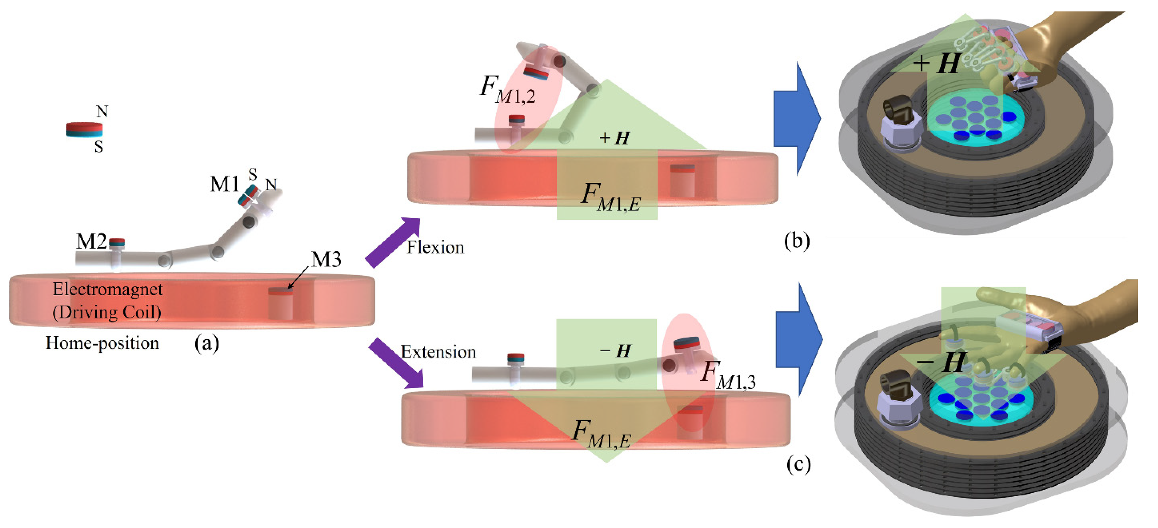
2.1. Principle of Wireless Manipulation for Finger Training

The proposed wireless manipulation method for finger flexion and extension using a magnetic control system exploits the magnetic force between an electromagnet and permanent magnets. The principles are shown in Figure 1. For finger flexion and extension, a magnet array (M1) is attached to the fingers, and attractive and repulsive forces are generated between the magnets and driving coil according to the coil-generated magnetic field direction. Figure 1a shows the basic configuration, consisting of the driving coil and three magnet arrays: M1, M2, and M3, on the fingers and palm, and in the driving coil, respectively. M1 facilitates the main finger actuation; M2 and M3 allow maximum flexion and extension through the FM1,2 and FM1,3 magnetic forces, respectively (the magnetic forces between M1 and M2 and M3, respectively). Figure 1b illustrates the finger flexion method. The green arrow indicates the magnetic field direction. For +H, repulsive FM1,E is generated towards M1, corresponding to finger flexion. Hence, M1 comes close to M2 on the palm and an attractive force that enhances the finger flexion occurs between M1 and M2. The proposed multi-link assist device containing multi-magnets (M1 array) maintains a stable posture for four-finger flexion. For a H field direction at the driving coil, attractive FM1,E occurs between M1 and the coil. Because of force direction, the device generates finger extension. When M1 is close to M3, the two magnet arrays enhance the finger extension (Figure 1c). Hence, we can define the forces acting to generate flexion and extension as follows: Flexion = FM1,E + FM1,2 and Extension = FM1,E + FM1,3.

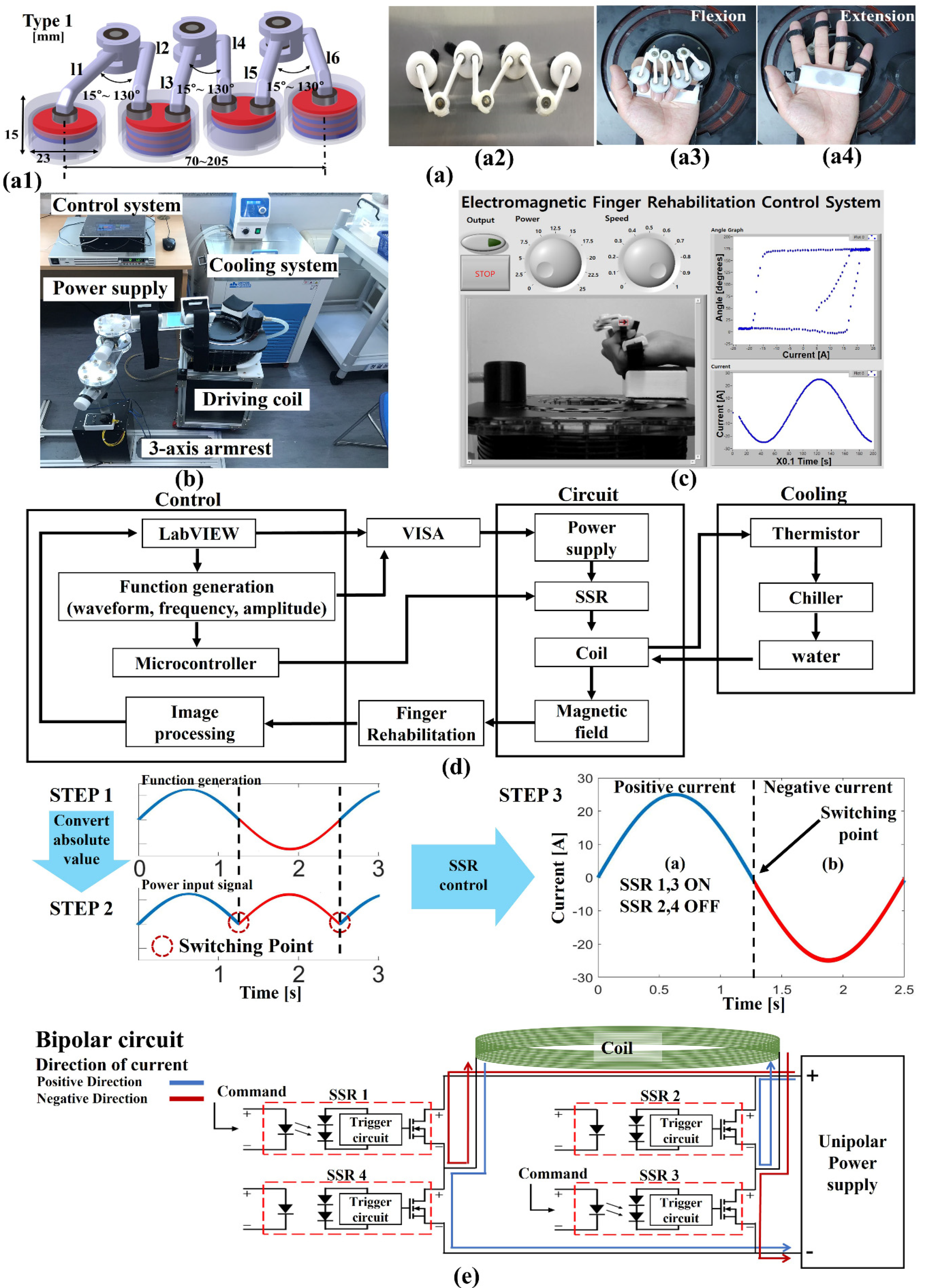
2.2. Magnetic Device Mechanism for Finger Movement and Overall System Configuration

For wireless finger training, we propose a multi-link magnet device a with wireless control method. Figure 2a1,a2 show the designed and fabricated magnet assist device, respectively; this device works to maintain the posture by limiting excessive magnetic attraction and repulsion through the magnetic forces of the inner-magnet. The multi-link magnet device consists of four containers, six links (l1 to l6), and 12 bearings (B1 to B9). Bearings B1, B4, and B7 are composed of pairs (two bearings) to connect link l1 and l2, l3 and l4, and l5 and l6, respectively. Their role is to maintain the angles between the fingers (β) that occur when the fingers are stretched and bent (extension and flexion), as shown `in Figure 2a3,a4. The fabricated links are different lengths because of the different finger lengths: l1, l3, and l5 are 34.72 mm in length, while l2, l4, and l6 are 30.21 mm. The device is lightweight, weighing only 90.3 g. Individuals have differently sized hands and, thus, the β values differ. Therefore, in the fabricated device, an inter-link angle (α) of a minimum of 15° to a maximum of 130° can be maintained by bearings B1, B4, and B7. When the hands are stretched, β is smaller than α. Therefore, the bearings B2, B3, B5, B6, B8, and B9 cause link rotation and produce natural hand movements. Because the inner diameter and depth of the fabricated four containers are 20 mm and 9 mm, respectively, we can mount up to three disc-type permanent magnets with diameters and thickness of up to 20 and 3 mm, respectively. The magnet type is N27 and remanence Br is 1.07 T. One, three, one, and three magnets are installed in each container, considering the force between the magnets. Figure 2b shows the overall control–system configuration. The system consists of the driving coil, 3-axis armrest, DC power supply, control circuit, and cooling system. As noted above, we developed a LabView-based control program for real-time observation of the driving coil and for hand motion analysis. Figure 2c shows the graphical user interface (GUI) developed using LabView. A gesture is tracked via a video camera for trajectory determination. Using the GUI, the hand movement speed and magnetic field strength can be controlled. Figure 2d shows the control block diagram. It is divided into three parts: control, power circuit, and cooling. The control part performs signal generation with control and image processing. The power circuit part converts unipolar current to bipolar current signal for the actuations.
When providing up to 25 A of current, the coil generates heat in excess of 100 °C. When the cooling system is set to a cooling temperature of 5 °C, a constant driving coil temperature guarantees a constant current supply and magnetic field, which are very important for generation of continuous changes in the magnetic field intensity in the working space; hence, finger flexion and extension are achieved. Figure 2e shows the signal converting process from unipolar current to bipolar current signal using solid-state relay (SSR) control with unipolar power supply. As DC power supply cannot change the direction of the current, the absolute value of the generated function is sent to the input signal of the power supply. The power supply outputs the same current waveform as the input signal. However, the polarity of the coil must be changed for extension and flexion movements. Therefore, a bipolar circuit is used to reverse the direction of the current. To generate a bipolar signal, we designed a bipolar circuit in which an SSR is incorporated into the control circuit, as shown in Figure 2e. The bipolar circuit was fabricated with four SSRs. The current direction can be changed by controlling the four SSRs. When SSR1,3 is turned on, the positive current flows up to 25 A at the driving coil. When SSR2,4 is turned on, the negative current flows up to −25 A at the driving coil. The control circuit with DC power supply provides up to 25 A to the driving coil. Through the SSR bipolar circuit and control of the unipolar DC power supply, we generated and controlled a sinusoidal wave.

2.3. Analysis of the Electromagnetic Control System

For wireless assistive finger movement, we developed an electromagnetic control system. The proposed driving system consists of a driving coil and permanent magnet array (M3) to generate the driving magnetic force. M3 was positioned in the inner space of the driving coil. Figure 3a shows the results of a COMSOL magnetic simulation of the combined magnetic field distribution from the magnets with the coil at the driving current of ± 25 A. When a 25 A current is applied, the coil becomes an electromagnet with the top and bottom as the N and S poles, respectively. Thus, the electromagnet polarity is opposite to that of M3, and there is a very low-strength magnetic field in the M3 region. However, the overall magnetic field distribution is directed upward of the coil, causing the finger flexion. When a −25 A current is applied, the polarity direction is the same for both the electromagnet and the magnet array.
In this case, the flux is directed from the coil top to the bottom and the field direction causes finger extension. Through the magnetic simulation performed in this study, we could predict the field distributions generated in the working space by the coil and magnet array. In conjunction with the simulation, we measured the actual magnetic field distributions using a gauss meter (F.W. Bell 5180 Milwaukie, OR, USA). Note that we developed a tailored measurement system involving both hardware and software, as shown in Figure 3b. The employed hardware was a 3-axis auto-scanning machine, in which the measuring probe could be moved with a minimum measurement distance of 1 mm. In this measurement, the XY plane was measured at 5 mm intervals, and the height (Z-axis) was measured at 10 mm intervals from the surface to a maximum of 100 mm. The measured data were transformed into a three-dimensional magnetic field distribution in the measurement program. In this system, the hand is positioned at a 66 mm height from the coil because this corresponds to the hand rest height. Therefore, the highest possible point of the finger trajectory was 100 mm. Figure 3c shows magnetic field distributions obtained for −25 A and 25 A applied currents at a height of 66 mm from the driving coil. It is apparent that the −25 A and 25 A currents generate average field strengths of 31.877 and 19.635 kA/m, respectively, in the working space.
As designed, the negative current in the driving coil generates a magnetic field in the same direction as that from the magnet array, whereas the positive current generates a magnetic field in the opposite direction to that of the magnet array. Therefore, the field distribution of 25 A is lower than that of −25 A. The applied −25 and 25 A currents induce maximum extension and flexion, respectively. Figure 3d shows magnetic field distributions at 96 mm height when the applied currents were −25 and 25 A, respectively, yielding average field strengths of 17.367 and 14.769 kA/m, respectively. The 66 and 96 mm heights correspond to maximum finger extension and flexion, respectively. Thus, the magnetic field strength due to the two maximum currents (±25 A) correspond to the maximum system driving range.

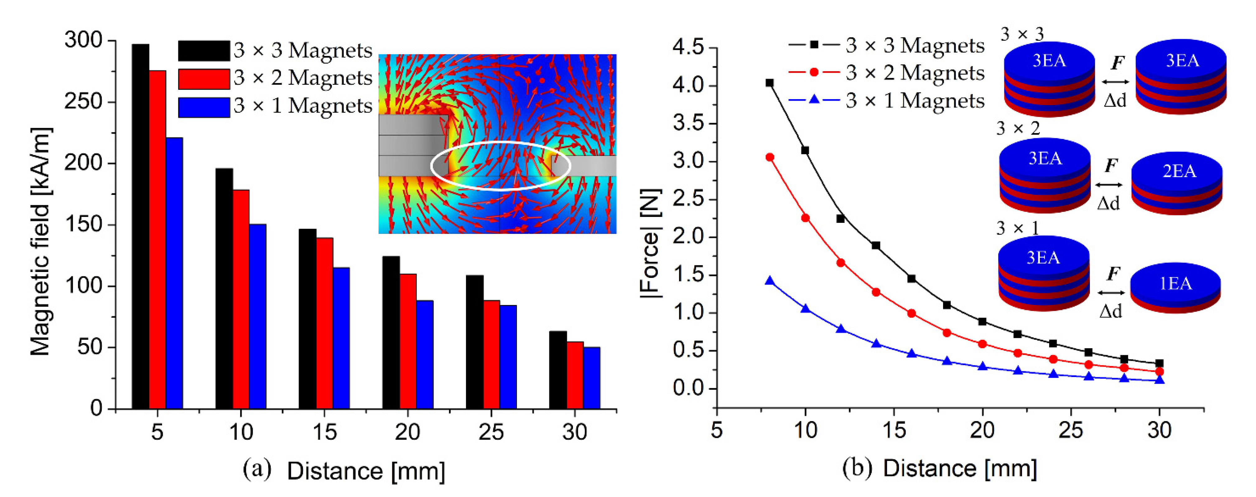
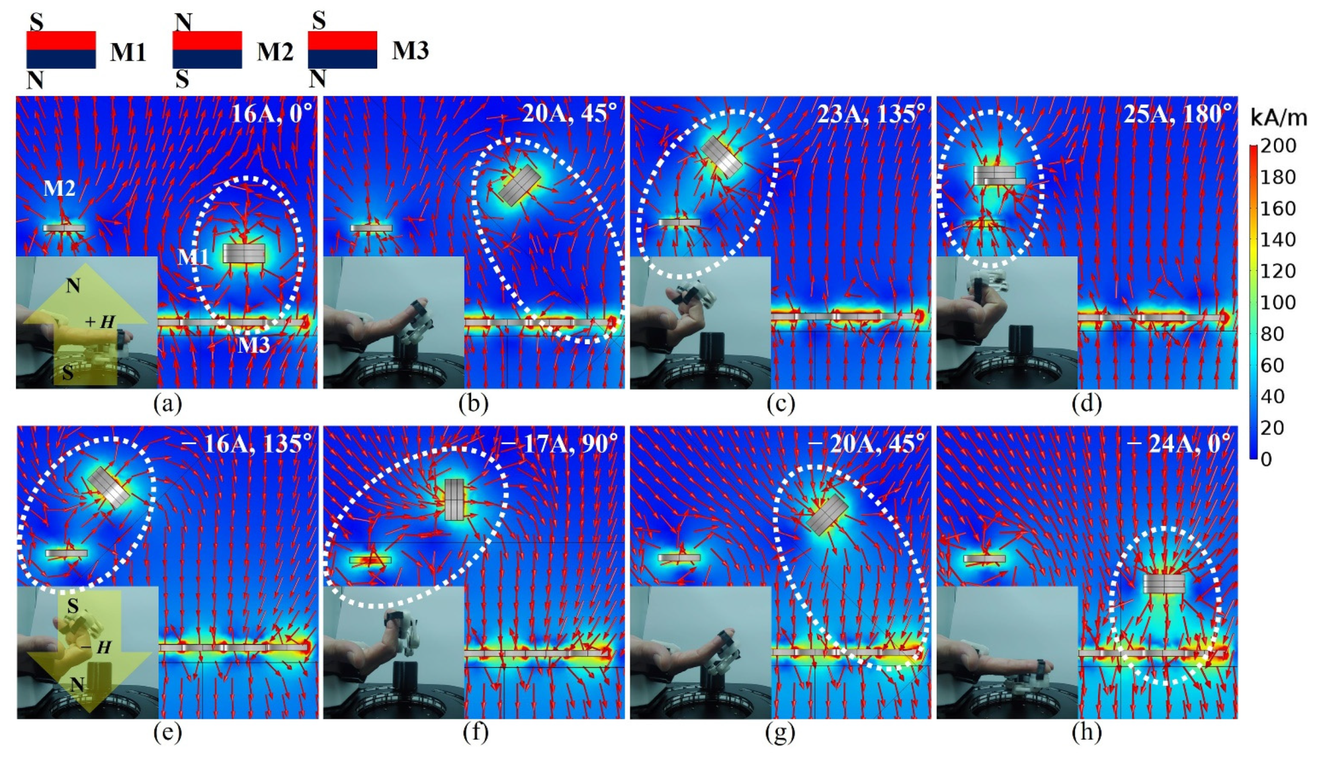
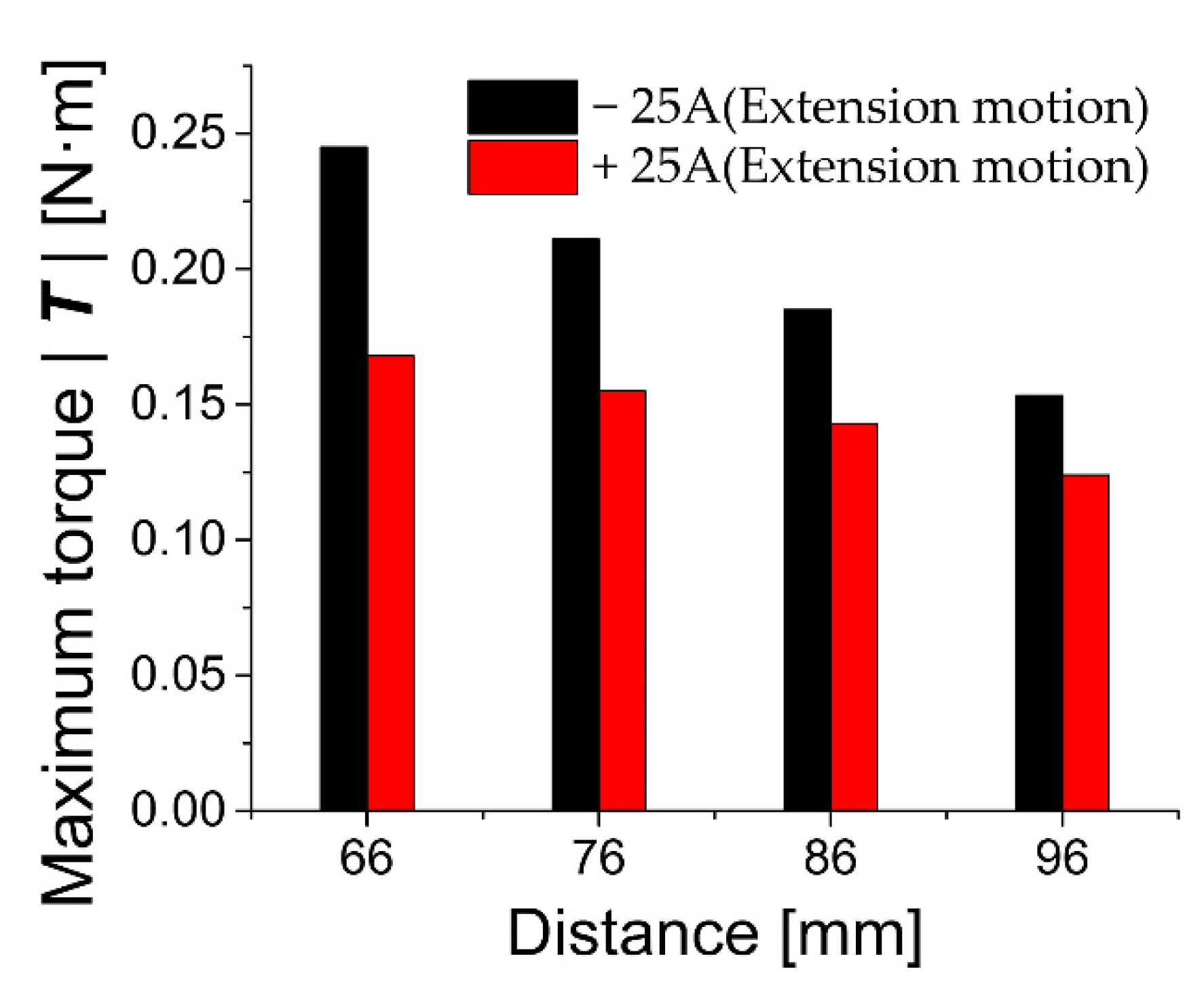
2.4. Interactions between Magnets in the Multi-Link Magnet Device

The magnetic forces between the multiple magnets in the four containers can facilitate and determine the natural finger movements (flexion and extension). Note that up to three disk magnets (3 mm thickness) can be installed in the fabricated containers. Although the fabricated multi-links maintain the finger positions, the magnets installed in the container can generate attractive or repulsive forces that disrupts natural flexion and extension. Therefore, we investigated interactions between magnets by conducting magnetic simulations and observing the field distributions, as shown in Figure 4. In the simulations, we examined the distribution and field strength according to changes in distance between the containers, as shown in Figure 4a.
Here, the containers contained (3, 3), (3, 2), and (3, 1) magnets, and the maximum separation distance was 30 mm, which was approached in 5 mm intervals. The results revealed that each paired magnet produces decoupled field distributions in accordance with the magnetic pole directions. When the two magnet sets in the fabricated device are closest to each other for finger flexion, their separation is approximately 8 to 10 mm. The simulation results indicate a 10 mm separation distance between two magnet sets, with the (3, 3), (3, 2), and (3, 1) containers producing field strengths of 195.79, 178.42, and 150.34 kA/m, respectively. The decoupled fields generated a repulsive force between magnet sets, as shown in Figure 4b. Note that excessive repulsion interferes with the natural grasping motion of the hand. For grasping, β should be minimized, but this angle is maintained by the repulsive force. The experiment revealed that the decoupled field distributions at 10 mm separation generate repulsive forces of 3.144, 2.25, and 1.04 N, respectively. If the repulsive force exceeds 2 N, the patient cannot generate a natural gripping motion because of the magnet repulsive force. Therefore, one, three, one, and three magnets are installed in four different containers.

3. Magnetic Device Analysis and Results

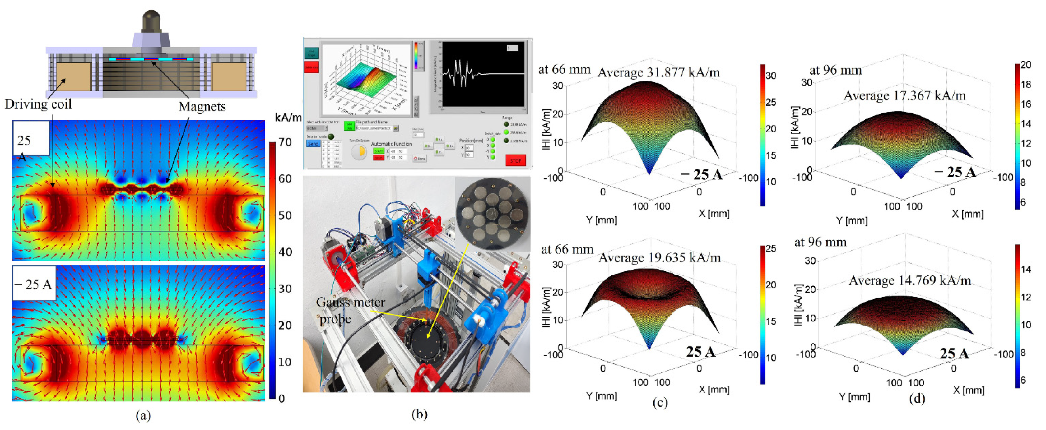
3.1. Validation of Multi-Link Magnet Device for Wireless Training

To verify the proposed mechanism, we performed various magnetic simulations using COMSOL software. We also performed multiple experiments. In the simulations, the finger position changes and the M1 driving currents were the same as in the actual experiments, as shown in Figure 5. Figure 5a–d show the finger flexion process up to a 25 A driving current. The generated magnetic field is directed upward as a result of the positive current. In the case shown in Figure 5a, M1 and M3 generate an attractive force and their flux direction is opposite to the field generated by the driving coil (16 A). In particular, FM1,3 is stronger than that between M1 and the electromagnet (FM1,E) at maximum extension.
When the driving current is 20 A, the generated magnetic field from the coil pushes M1. Under that condition, we can observe that the magnetic fluxes from M1 and the coil repel each other. In that case, FM1,E is stronger than FM1,3. The increased driving currents further increase the bending of the finger via the stronger FM1,E. At this time, M1 is close to M2, which is on the palm, and an attraction force FM1,2 is generated between M1 and M2, yielding the maximum grasping motion, as shown in Figure 5c,d. In that case, the 25 A driving current generates a maximum flexion angle of 180°. For finger extension, we changed the driving current from 25 to −25 A. In Figure 5e, the field generated by the coil exhibits initial extension due to strong FM1,2 between M1 and M2 at a −16 A driving current. In that case, the driving magnetic force FM1,E is stronger than FM1,2. Because of downward field from the negative current, M1 moves in the field direction (finger extension), as shown in Figure 5f–h. Moreover, when M1 is close to M3, FM1,3 can enhance the finger stretching motion, as shown in Figure 5h. Therefore, through simulation, we successfully confirmed the magnetic coupling condition according to changes in the M1 position due to variations in the driving current for flexion and extension. In particular, the magnetic axial coupling between M1 and M2 or between M1 and M3 enhances the finger movement induced by FM1,2 and FM1,3.
In addition, the magnetic device generates magnetic torque in the applied magnetic field. Figure 6 shows the calculated maximum magnetic torque at the positive and negative driving currents of ± 25 A. For torque calculation, we used the measured magnetic field flux density using the device in Figure 3b. There are a total of eight cylindrical permanent magnets built into the multi-link magnet device. When wearing a multi-link magnet device, all fingers are restricted to moving together, so the torque generated by each magnet was calculated and all the results were summed. A magnetic torque can be expressed as follows:
τ = m × B
where m is the magnetic moment and B is the external magnetic field. The magnetic moment value of the permanent magnet can be calculated from the residual magnetic flux density Br by the following equation:
m = 1 μ 0 B r V
where μ 0 is the permeability of vacuum ( H / m ) and V is the volume of the magnet. During the flexion and extension movement, the position of the device produces maximum torque at a height of 66 to 96 mm from the coil surface. In this height range, it can be confirmed that the angle between the magnetic field and the magnetic moment is 90 degrees. During the extension movement, magnetic torque is 0.245 and 0.1533 N·m at 66 and 96 mm, respectively, whereas the flexion movement shows a maximum torque of 0.168 and 0.124 N·m at 66 and 96 mm, respectively. In the results, the average decrease in magnetic torque is 0.014 N·m according to changes in height during flexion motion, whereas the extension motion represented an average decrease of 0.03 N·m. In the case of the maximum extension torque, the directions of total magnetic field are same between the magnetic field from the coil and the magnetic field from M3. In the case of the maximum flexion torque, the applied total magnetic field density is lower than the extension motion because the applied magnetic field directions from the driving coil and M3 is different. Therefore, the maximum flexion torque is lower than that of the extension motion.

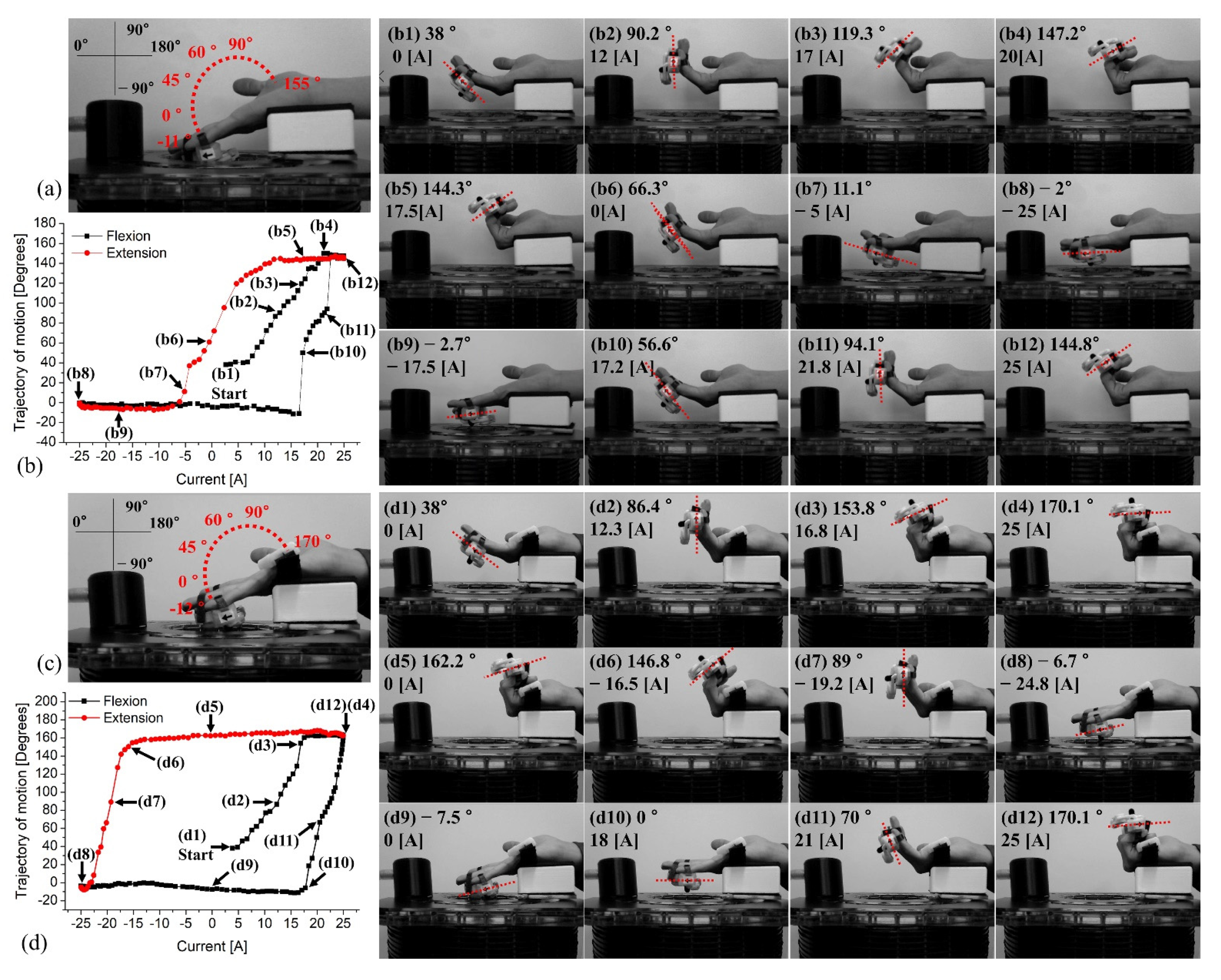
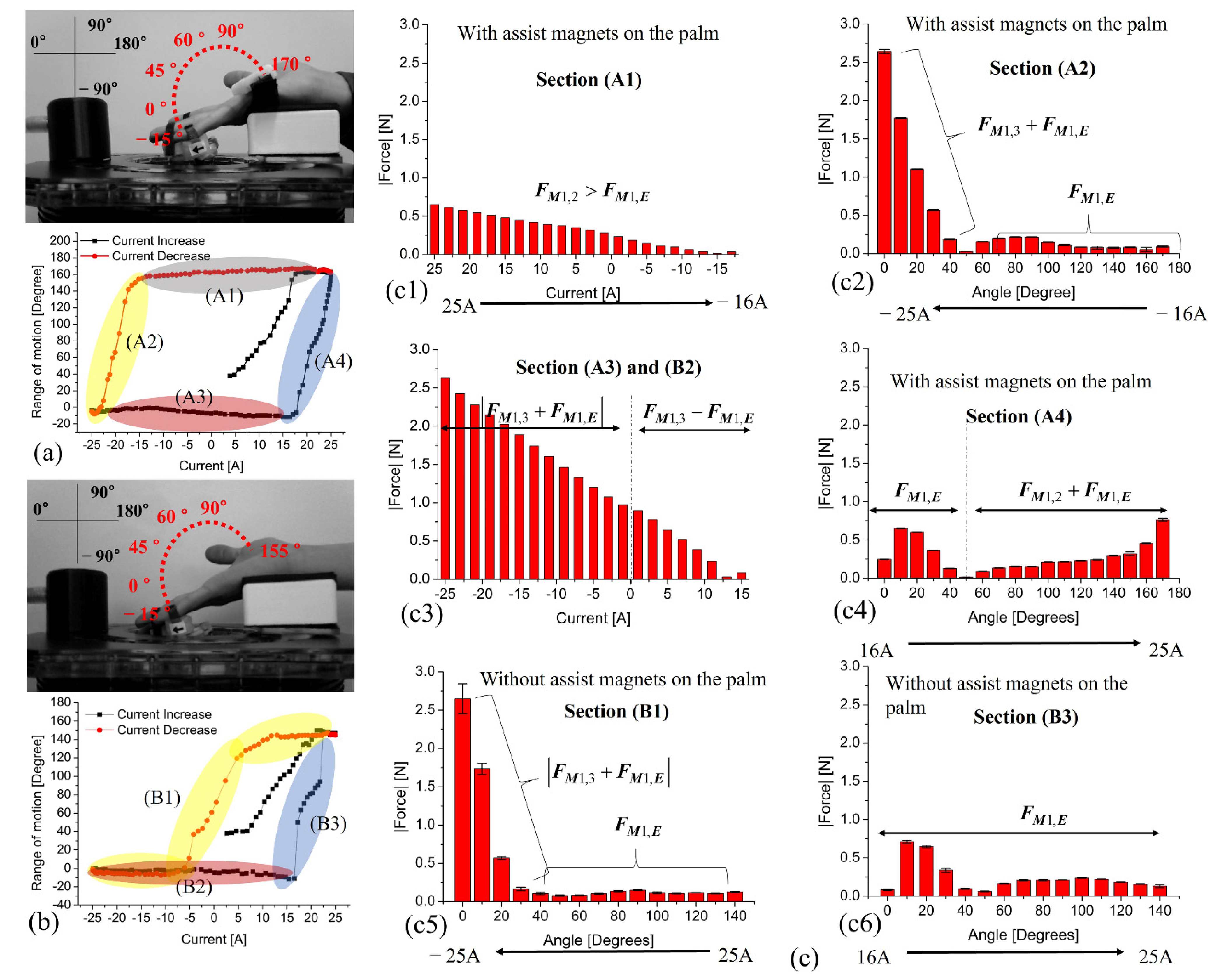
3.2. Motion Analysis of Multi-Link Magnet Device

Using the designed multi-link magnet device, we performed motion analysis based on video tracking according to changes in the driving current, considering two cases. That is, finger movements with and without the M2 auxiliary magnet on the palm were observed for comparison for a 0.4 Hz driving frequency, as shown in Figure 7. First, we observed finger flexion and extension without M2, as shown in Figure 7a. In that case, the maximum movement range was found to be −15 to 150° at a driving range of −25 to 25 A. Figure 7b shows the motion trajectory for flexion and extension without M2, while Figure 7b1–b12 show the finger positions according to the driving current variations. The black and red dotted lines in Figure 7b indicate finger flexion and extension, respectively. For finger flexion, the driving current varied from 0 A to 25 A. With no current, the fingers have initial and maximum angles of 38° and 155°, respectively, with a maximum current of 25 A, corresponding to the position shown in Figure 7b1–b3. Figure 7b4–b8 corresponds to the extension trajectories for driving-current variation from 25 A to −25 A. The finger angle decreases from 155° to 60° while the driving current reduction from 25 to 0 A (Figure 7b4–b7). For −8.3 A driving current, a maximum stretched finger angle of approximately −7° appears; this is maintained up to −25 A because of FM1,3. Although the driving current is positive to approximately 16.5 A, the attractive force FM1,3 maintains the extended position. At 17.2 A, the finger angle increases rapidly to 56.6° (Figure 7b10). Above 17 A, the finger movement changes rapidly from extension to flexion (16–25 A), as shown in Figure 7b10–b12. In the second experiment, flexion and extension motions were observed for a device containing M1, M2, and M3, as shown in Figure 7c.
In this configuration, FM1,E between M1 and the driving coil generates basic finger flexion and extension, while FM1,2 and FM1,3 enhance the flexion and extension and maintain the maximum flexion and extension, improving the training effect. Because of the effect of FM1,2, a maximum flexion angle of approximately 170° appears, which is maintained at 146.8° until a −16.5 A driving current, as shown in Figure 7d1–d6. Next, M1 on the finger accelerates under the influence of FM1,E and FM1,3, and the two forces produce a rapid stretching motion for a small −8 A current variation, as shown in Figure 7d6–d8. In particular, FM1,3 maintains stretching motion, which can improve the training effect up to a driving current of approximately 18 A, as shown in Figure 7d8–d10. In this case, although the driving current is positive, the generated FM1,E is weaker than FM1,3 such that the stretching motion is maintained. A bending motion occurs when the driving current exceeds 18 A, and the motion changes occur quickly in response to the stronger FM1,E with the assisting force FM1,2, as shown in Figure 7d10–d12. A comparison of the two methods examined in the above experiments reveals that the use of auxiliary magnets M2 and M3 yields greater finger movement. Note that the experimenter’s hand muscle strength was not used, and the hand was actively moved by magnetic forces only. Furthermore, both FM1,2 and FM1,3 can manually improve hand muscle strength without an external magnetic field because the two forces interfere with finger movement.
Thus, through magnetic simulation and motion analysis, we confirmed active extension and flexion for wireless training using magnetic coupling. Furthermore, we observed the force generated during hand movement according to changes in the driving current and finger angle, as shown in Figure 8. For the force analysis, we analyzed the results for the maximum bending point by dividing them into sections to match the trajectory of motion. As mentioned above, Figure 8a,b shows the trajectories for the divided sections obtained with and without M2. The results indicate that, when the driving current is changed from 25 to −16 A in Section A1, the finger angle (finger device) is maintained at approximately 170° and the generated force changes from 0.651 to 0.034 N, as shown in Figure 8c1. The applied positive current produces two forces that can be summed (FM1,2 + FM1,E) in Section A1, whereas the negative current causes the decreased driving force because of the corresponding force difference (FM1,2FM1,E). Note that, because of the bending-motion holding section according to changes in the driving current, the acting force tends to gradually decrease as the current changes. Section A2 corresponds to the range in which the bending motion changes to a stretching motion, as the driving current moves from −16 to −25 A. In this section, the change in motion (finger angle) is very fast compared to the change in driving current because of the driving force variations, as shown in Figure 8c2.
When the finger angle is 170° to 50°, the rate of change of FM1,E is low and the average force is approximately 0.252 N. However, when the angle is less than 40°, the driving force increases rapidly to 2.634 N, due to the combined forces (FM1,3 + FM1,E). Section A3 and B2 correspond to the maximum maintained hand stretching induced by driving current variations from −25 to 15 A. Because the stretched finger angle is maintained, the acting force gradually decreases from 2.643 to 0.083 N according to the driving current, as shown in Figure 8c3. Thus, the applied negative current induced a combined force of FM1,3 + FM1,E, while the −25-A driving current generates a maximum force of 2.643 N. The applied positive current from 0 to 16 A induced an acting force of FM1,3FM1 and the applied current of 16 A generates a 0.083 N force. Section A4 shows the variations in force for flexion from 16 to 25 A. In this case, when the finger angle reaches approximately 40°, the driving force depends on FM1,E. At approximately 16 A, because the finger bends momentarily and shakes, the force distribution rapidly increases and decreases with angle changes from 0° to 40°. In the angle range exceeding 40°, the finger is stably bent, and the two forces (FM1,2 + FM1,E) are added as the driving current increases, as shown in Figure 8c4. The force acting on the finger device under the maximum driving current reaches 0.764 N. Figure 8b shows the trajectory of motion and sections for the device without M2. In this case, we established three sections labeled B1 to B3, corresponding to the extension, the maintained stretched motion, and the flexion, respectively. Although Sections A1 and B1 both correspond to the flexion section, B1 differs from A1 as the former is not influenced by M2. Changes in finger angle from 155° to 40° depend on the influence of FM1,E and the variations in force are not large (average 0.12 N). In contrast, the finger angle from 40° or lower depends on FM1,3 + FM1,E because of the negative current, as shown in Figure 8c5. Under these conditions, the force for maximum stretching is 2.64 N, and the maximum change in force in the extension section differs by 22 times; that is, the average and maximum forces are 0.12 and 2.64 N, respectively. In Section B3, the driving-force rate of change is large at 10°. This is because the bending motion occurs instantaneously with the increase in FM1,E due to the driving current of approximately 17 A. After a 40° finger angle has been reached, however, the driving force stabilizes, as shown in Figure 8c6. Although Section B3 and A4 are similar, the former depends only on FM1,E from finger angles of 40° to 155°.

4. Discussion and Conclusions

The developed devices and control system generate magnetic force and torque for wireless assistive finger training. In our previous work, we focused on the development of the wireless driving method, but the resultant system could not exercise multiple fingers simultaneously. In this study, we used the wireless driving concept developed in the previous study to verify the proposed device and their performance. Hence, it was confirmed that the device can move four fingers simultaneously for flexion and extension motion. The fabricated device has the advantage of generating natural finger movement. To validate the developed driving system, we developed a device and measurement software that can scan and measure the magnetic field in three dimensions. In addition, by using a video-based real-time observation system, we can observe movement trajectories during hand movements for quantitative motion analysis.
The device was designed to prevent interference between the magnets on the fingers and generate natural finger movement. In particular, in the fabricated multi-link magnet device, the magnets are installed inside four containers; therefore, the coupling between these magnets is very important. To determine the appropriate setup, the numbers of magnets installed in the various containers were determined through simulation and experiment. Note that the natural hand motion (flexion) is disturbed if the magnetic force between the containers is large. However, it was confirmed that the proposed structure, mechanical elements, and the balanced magnetic coupling maintain a natural finger posture. Stroke patients have difficulty maintaining natural finger posture. Thus, the proposed device is very important. Furthermore, the device provides natural flexion and extension according to changes in magnetic field strength and direction, allowing wireless operation. In addition, the overall system configuration allows application as a passive training device. That is, if the patient’s hand has muscle strength, they can exercise this strength using the magnetic coupling force FM1,2 and FM1,3 without FM1,E, i.e., applying the system as a passive training device.
The developed devices are lightweight, have very simple structures and configuration, and have good wearability on the hand as they do not act as a load. In fact, these features are most important for training or rehabilitation devices or systems. In particular, the magnetic force and torque can provide wireless actuation of the two devices because of these features. Finally, because of the height of the hand rest, the magnetic force for the flexion motion was decreased. By reducing the height of the hand rest or increasing the driving current, we can increase the magnetic force for finger flexion (FM1,E). We have proposed devices and a control system (including a motion tracking system) for wireless finger training. In the proposed control system, the hand position must be fixed for finger training because a single driving coil is used. Therefore, we are developing a three-axis coil-based control system for more convenient assistive finger training. By sensing the hand position, the control system will automatically change the driving coil or the current phase to generate a magnetic field suitable for the flexion and extension of the hand in the given position.

Author Contributions

D.-M.J. designed and conducted experiments and wrote and edited the manuscript. M.-S.K. and S.-H.K. obtained resources, provided the main idea for the control method and system configuration, and verified the implemented system and edited the manuscript. All authors have read and agreed to the published version of the manuscript.

Funding

This work was supported in part by the Korea Medical Device Development Fund grant funded by the Korean government (the Ministry of Science and ICT, the Ministry of Trade, Industry and Energy, the Ministry of Health & Welfare, the Ministry of Food and Drug Safety) (Project Number: KMDF_PR_20200901_0130, 9991006803), in part by the Basic Science Research Program of the Ministry of Science & ICT under grant 2020R1A4A3079595, and in part by the National Research Foundation of Korea (NRF) grant funded by the Korean government (the Ministry of Science & ICT, the Ministry of education) under the grant 2018R1C1B6003491 and the grant 2018R1D1A1A02048673.

Institutional Review Board Statement

Not applicable.

Informed Consent Statement

Not applicable.

Data Availability Statement

Data can be requested from the corresponding authors.

Conflicts of Interest

The authors declare no conflict of interest.

References

  1. Duncan, P.W.; Zorowitz, R.; Bates, B.; Choi, J.Y.; Glasberg, J.J.; Graham, G.D.; Katz, R.C.; Lamberty, K.; Reker, D. Management of Adult Stroke Rehabilitation Care. Stroke 2005, 36, e100–e143. [Google Scholar] [CrossRef]
  2. Wissel, J.; Olver, J.; Sunnerhagen, K.S. Navigating the Poststroke Continuum of Care. J. Stroke 2007, 22, 1–8. [Google Scholar] [CrossRef] [PubMed]
  3. Bouzit, M.; Burdea, G.; Popescu, G.; Boian, R. The Rutgers MasterII—New design force-feedback glove. IEEE/ASME Trans. Mechatron. 2002, 7, 256–263. [Google Scholar] [CrossRef] [Green Version]
  4. Lee, S.; Landers, A.; Park, H.S. Development of a Biomimetic Hand Exotendon Device (BiomHED) for Restoration of Functional Hand Movement Post-Stroke. IEEE Trans. Neural Syst. Rehabil. Eng. 2014, 22, 886–898. [Google Scholar] [CrossRef] [PubMed] [Green Version]
  5. Chiri, A.; Vitiello, N.; Giovacchini, F.; Roccella, S.; Vecchi, F.; Carrozza, M.C. Mechatronic Design and Characterization of the Index Finger Module of a Hand Exoskeleton for Post-Stroke Rehabilitation. IEEE/ASME Trans. Mechatron. 2012, 17, 884–894. [Google Scholar] [CrossRef]
  6. Brokaw, E.B.; Black, I.; Holley, R.J.; Lum, P.S. Hand Spring Operated Movement Enhancer (HandSOME): A Portable, Passive Hand Exoskeleton for Stroke Rehabilitation. IEEE Trans. Neural Syst. Rehabil. Eng. 2011, 19, 391–399. [Google Scholar] [CrossRef]
  7. In, H.; Kang, B.B.; Sin, M.; Cho, K.J. Exo-Glove: A Wearable Robot for the Hand with a Soft Tendon Routing System. IEEE Robot. Autom. Mag. 2015, 22, 97–105. [Google Scholar] [CrossRef]
  8. Ueki, S.; Kawasaki, H.; Ito, S.; Nishimoto, Y.; Abe, M.; Aoki, T.; Ishigure, Y.; Ojika, T.; Mouri, T. Development of a Hand-Assist Robot with Multi-Degrees-of-Freedom for Rehabilitation Therapy. IEEE/ASME Trans. Mechatron. 2012, 17, 136–146. [Google Scholar] [CrossRef]
  9. Fischer, H.C.; Triandafilou, K.M.; Thielbar, K.O.; Ochoa, J.M.; Lazzaro, E.D.; Pacholski, K.A.; Kamper, D.G. Use of a Portable Assistive Glove to Facilitate Rehabilitation in Stroke Survivors with Severe Hand Impairment. IEEE Trans. Neural Syst. Rehabil. Eng. 2016, 24, 344–351. [Google Scholar] [CrossRef]
  10. Jones, C.L.; Wang, F.; Morrison, R.; Sarkar, N.; Kamper, D.G. Design and Development of the Cable Actuated Finger Exoskeleton for Hand Rehabilitation Following Stroke. IEEE/ASME Trans. Mechatron. 2014, 19, 131–140. [Google Scholar] [CrossRef]
  11. Schabowsky, C.N.; Godfrey, S.B.; Holley, R.J.; Lum, P.S. Development and pilot testing of HEXORR: Hand EXOskeleton Rehabilitation Robot. J. NeuroEng. Rehabil. 2010, 7, 1–36. [Google Scholar] [CrossRef] [PubMed] [Green Version]
  12. Ma, Z.; Ben-Tzvi, P.; Danoff, J. Hand Rehabilitation Learning System with an Exoskeleton Robotic Glove. IEEE Trans. Neural Syst. Rehabil. Eng. 2016, 24, 323–1332. [Google Scholar] [CrossRef] [PubMed]
  13. Cheng, L.; Chen, M.; Li, Z. Design and Control of a Wearable Hand Rehabilitation Robot. IEEE Access 2018, 6, 74039–74050. [Google Scholar] [CrossRef]
  14. Kosar, T.; Lu, Z.; Mernik, M.; Horvat, M.; Črepinšek, M. A Case Study on the Design and Implementation of a Platform for Hand Rehabilitation. Appl. Sci. 2021, 11, 389. [Google Scholar] [CrossRef]
  15. Mosadegh, B.; Polygerinos, P.; Keplinger, C.; Wennstedt, S.; Shepherd, R.F.; Gupta, U.; Shim, J.; Bertoldi, K.; Walsh, C.J.; Whitesides, G.M. Pneumatic Networks for Soft Robotics that Actuate Rapidly. Adv. Funct. Mater. 2014, 24, 2163–2170. [Google Scholar] [CrossRef]
  16. Polygerinos, P.; Wang, Z.; Galloway, K.C.; Wood, R.J.; Walsh, C.J. Soft robotic glove for combined assistance and at-home rehabilitation. Robot. Auton. Syst. 2015, 73, 135–143. [Google Scholar] [CrossRef] [Green Version]
  17. Rose, C.G.; Omalley, M.K. Hybrid Rigid-Soft Hand Exoskeleton to Assist Functional Dexterity. IEEE Robot. Autom. Lett. 2019, 4, 73–80. [Google Scholar] [CrossRef]
  18. Wang, J.; Fei, Y.; Pang, W. Design, Modeling, and Testing of a Soft Pneumatic Glove with Segmented PneuNets Bending Actuators. IEEE/ASME Trans. Mechatron. 2019, 24, 990–1001. [Google Scholar] [CrossRef]
  19. Yap, H.K.; Khin, P.M.; Koh, T.H.; Sun, Y.; Liang, X.; Lim, J.H.; Yeow, C.H. A Fully Fabric-Based Bidirectional Soft Robotic Glove for Assistance and Rehabilitation of Hand Impaired Patients. IEEE Robot. Autom. Lett. 2017, 2, 1383–1390. [Google Scholar] [CrossRef]
  20. Silva, A.F.G.; Goncalves, A.F.; Mendes, P.M.; Correia, J.H. FBG Sensing Glove for Monitoring Hand Posture. IEEE Sens. J. 2011, 11, 2442–2448. [Google Scholar] [CrossRef]
  21. Borghetti, M.; Sardini, E.; Serpelloni, M. Sensorized Glove for Measuring Hand Finger Flexion for Rehabilitation Purposes. IEEE Trans. Instrum. Meas. 2013, 62, 3308–3314. [Google Scholar] [CrossRef]
  22. Alamri, A.; Cha, J.; Saddik, A.E. AR-REHAB: An Augmented Reality Framework for Poststroke-Patient Rehabilitation. IEEE Trans. Instrum. Meas. 2010, 59, 2554–2563. [Google Scholar] [CrossRef]
  23. Levin, M.F.; Magdalon, E.C.; Michaelsen, S.M.; Quevedo, A.A.F. Quality of Grasping and the Role of Haptics in a 3-D Immersive Virtual Reality Environment in Individuals with Stroke. IEEE Trans. Neural Syst. Rehabil. Eng. 2015, 23, 1047–1055. [Google Scholar] [CrossRef] [PubMed]
  24. Alamri, A.; Eid, M.; Iglesias, R.; Shirmohammadi, S.; Saddik, A.E. Haptic Virtual Rehabilitation Exercises for Poststroke Diagnosis. IEEE Trans. Instrum. Meas. 2008, 57, 1876–1884. [Google Scholar] [CrossRef]
  25. Castiblanco, J.C.; Mondragon, I.F.; Alvarado-Rojas, C.; Colorado, J.D. Assist-As-Needed Exoskeleton for Hand Joint Rehabilitation Based on Muscle Effort Detection. Sensors 2021, 21, 4372. [Google Scholar] [CrossRef]
  26. Gomez-Donoso, F.; Escalona, F.; Nasri, N.; Cazorla, M. A Hand Motor Skills Rehabilitation for the Injured Implemented on a Social Robot. Appl. Sci. 2021, 11, 2943. [Google Scholar] [CrossRef]
  27. Baek, I.C.; Kim, M.S.; Kim, S.H. A Novel Nonmechanical Finger Rehabilitation System Based on Magnetic Force Control. J. Magn. 2017, 22, 155–161. [Google Scholar] [CrossRef] [Green Version]
  28. Baek, I.C.; Jeon, G.H.; Yu, C.H.; Kim, K.; Kim, H.S. Wireless Active Finger Rehabilitation Method Using Three-Axis Electromagnetic Manipulation. IEEE Trans. Magn. 2017, 53, 9100705. [Google Scholar] [CrossRef]
Figure 1. Principles of wireless assistive finger training: (a) overall configuration for finger movement; (b) finger flexion method using positive driving current, where FM1,2 is the magnetic force between M1 and M2 and FM1,E is the magnetic force between M1 and the electromagnet (driving coil); (c) finger extension method using negative driving current, where FM1,E is the magnetic force between M1 and the electromagnetic and FM1,3 is the magnetic force between M1 and M3.
Applsci 11 06762 g001
Figure 2. (a) Configuration and mechanism of multi-link magnet assist device for flexion and extension. (b) Control system configuration. (c) Developed control software: the software can control the magnetic field strength and speed and observe and display the trajectory of motion using a video camera and monitor. (d) Total control diagram for the system. (e) Configuration of the driving circuit for current direction control at the driving coil and SSR control sequence for generation of sine wave current.
Applsci 11 06762 g002
Figure 3. Control–system analysis using a magnetic simulation and magnetic field measurement: (a) simulation results including M3 at 25 and −25 A; (b) developed 3-axis measurement system and LabView-based instrumentation software; (c) measured magnetic field distributions with −25 and 25 A driving currents at 66 mm high initial hand position (the −25 A case produced a stronger field distribution because of the M3 direction); (d) field distributions for −25 and 25 A at 96 mm height (the height indicates the finger position at 90°).
Applsci 11 06762 g003
Figure 4. (a) Magnetic field distribution according to the magnet number installed in containers and (b) magnetic force measurement according to magnet numbers for the equivalent condition of (a).
Applsci 11 06762 g004
Figure 5. Magnetic simulation results according to changes in finger positions due to driving current variation. (ad) Finger flexion: actual positions for driving currents of 16, 20, 23 and 25 A, and their magnetic couplings in magnetic simulations. (eh) Extension motion due to negative driving currents from −16 to −24 A and their magnetic couplings in magnetic simulations.
Applsci 11 06762 g005
Figure 6. Magnetic torque calculation according to height, with the negative driving currents represented by black bars and the positive by red bars.
Applsci 11 06762 g006
Figure 7. Observation of motion trajectory (the red line is an extension motion trajectory and the black line is a flexion motion trajectory): (a) device configuration and total range of movement; (b) trajectory of motion from −25 A to 25 A; (b1–b12) finger positions without M2 on palm; (c) device configuration and total range of movement including M2; (d) trajectory of motion for overall system, where d1–d3 show the finger positions according to variations in the driving current.
Applsci 11 06762 g007
Figure 8. (a) Trajectory of motion and Section A1 to A4, classified according to combination of M1, M2, and M3. (b) Trajectory of motion and the divided section from B1 to B3 without M2. (c) Variations in acting forces: (c1) and (c2) show the force acting in Section A1 and A2, respectively; (c3) shows the acting forces in Sections A3 and B2; (c4) shows the acting force in Section A4; (c5) and (c6) show the variations in the acting forces of Section B1 and B3, respectively.
Applsci 11 06762 g008
Publisher’s Note: MDPI stays neutral with regard to jurisdictional claims in published maps and institutional affiliations.

