1. Introduction
With the rapid development of science and technology, various high-tech equipment is confronted with serious vibration isolation and buffering problems in specific environments. Engineering systems such as vehicles, ships, spacecraft, bridges, etc., are often subjected to various excitations, inevitably leading to various vibrations. When the components in the equipment cannot withstand the harsh mechanical environment, vibration isolation or shock absorption is desperately needed. At present, due to the relative flexibility of rubber materials, they can withstand up to 100% deformation and reinstate their original shapes after stress is released [
1]. Consequently, they are widely used as vibration damping materials in a range of engineering fields. Notably, rubber isolators play an irreplaceable role as metal isolators especially in environments with special requirements, such as nonmagnetic requirements. Furthermore, modern engineering technology puts forward higher expectations and stricter requirements for solving vibration problems, yearning for thorough investigations of the dynamic characteristics of the rubber isolator.
Despite the extensive use of rubbers in a variety of fields, the understanding of the characteristics of rubber materials is still relatively limited. Therefore, efforts need to be devoted to the research of the dynamic characteristics and fatigue lifetime of rubber isolators to improve vibration damping performance. The mechanical properties of rubber materials exhibit very complex behaviors, and the behavior under stress and deformation is generally nonlinear. References [
2,
3,
4] introduced a detailed explanation of the nonlinear physical mechanism of rubber materials. The performance parameters of rubber isolators mainly refer to dynamic stiffness and dynamic damping, which not only depend on the chemical composition of the rubber material, but also on temperature, humidity, vibration frequency, and vibration amplitude. Of note, the rubber geometry also makes a difference [
5,
6,
7]. If the impact of nonlinearity on the dynamic characteristics of rubber materials could be fully understood, it would be possible to adopt new ways to improve the mechanical properties of rubber materials.
Due to fatigue, aging, and other factors, the stiffness of the rubber isolator tends to transform with altered dynamic characteristics and load-bearing capacity. Stiffness failure is defined when the stiffness of the rubber isolator transforms by more than 50%. Due to numerous factors affecting the lifetime of rubbers, such as mechanical load (load amplitude, load ratio, load frequency, etc.) and the atmosphere (oxygen, ozone, water vapor, etc.), a comprehensive description of the fatigue characteristics of the rubbers and accurate prediction of the lifetime of the vibration isolator remain as technical barriers [
8]. Generally speaking, the increase in the amplitude of a cyclic load leads to a decrease in the activation energy of the chemical reaction in the fatigue process, which makes it easier for the oxidation reaction to proceed and reduces the fatigue lifetime of rubber materials [
9,
10,
11]. Therefore, the effect of mechanical vibration on the lifetime of rubber still needs further investigation.
This paper is mainly divided into three parts to identify the dynamic mechanical properties of a rubber isolator when subjected to vibration excitation and investigate the fatigue lifetime of the rubber isolator. Firstly, the structure of the experimental system is briefly introduced, and the vibration test of the rubber isolator is carried out; then the mechanical model from the system structure is extracted, and the mathematical model of the rubber isolator is established and analyzed based on mechanics theory; finally, a fatigue lifetime prediction model of rubber isolators is established, and the influence of different load masses on the fatigue lifetime of the rubber isolator is explored.
2. Vibration Test Method
This paper mainly studies the nonlinear mechanical characteristics and fatigue lifetime of a thin-walled hollow spherical rubber isolator.
Figure 1 illustrates the external structure and geometric dimensions of the rubber isolator. The nonlinear dynamic characteristics of rubber isolators are obtained through harmonic and random vibration testing and analysis.
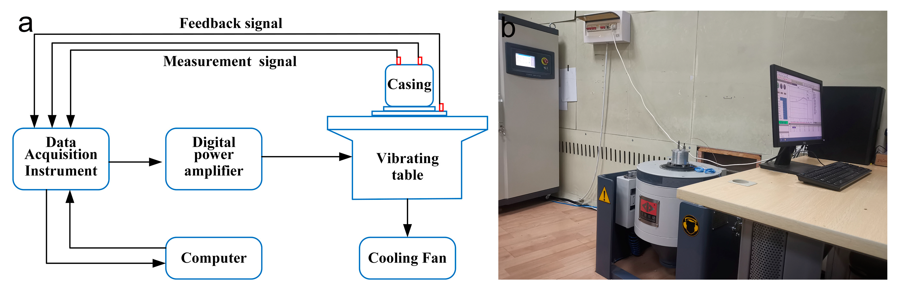
Figure 2a illustrates the fundamental principle of the vibration system.
Figure 2b shows the photo of the vibration system. The experimental system was mainly composed of a data acquisition instrument, a power amplifier, a computer, a digital vibration table, and acceleration sensors. The vibration table (ES-3-150, Dongling Co., Ltd., Suzhou, China) has a frequency range of [5; 4000] Hz. The maximum load of the vibration table (vertical direction) reaches 120 kg. The sensitivity of the acceleration sensors (PCB Piezotronic, 352a24) is 100 mV/g. The measurement error scope of the sensors is assured to be within ±5% in the frequency range of [1; 8000] Hz. In the experiment, the excitation signal was amplified by the power amplifier to prompt the moving parts of the shaker to vibrate. Meanwhile, the excitation feedback signal was used to ensure the stability of the input signal frequency and amplitude in real time. After the dual-channel vibration signal connected to the tooling was processed by the data acquisition instrument, the experimental data were transmitted to the computer.
The system structure is presented in
Figure 3a. The system structure was mainly composed of a vibration table, casing, a rubber isolator, a mass, and accelerometers.
Figure 3b shows the installation method of the rubber isolator and the location diagram of the acceleration sensor. A3 is the accelerometer for the control signal, and A1 and A2 are the output accelerometers. In this experiment, the linear bearing and the guide shaft were used to suppress the vibration mode of the isolator in other directions. Meanwhile, two accelerometers were positioned symmetrically along 180° at the bottom of the mass block with acceleration levels averaged to minimize the potential tilting.
The vibration experiment adopted the average control method. The control signal was a single channel. The test signal was a dual channel. The nonlinear characteristics of rubber isolators under harmonic and random vibrations were tested. For harmonic vibrations, experiments were carried out by changing the acceleration excitation levels. The experimental load was 50 g, and the acceleration level of the input excitation was dense with small values and loose with large values, i.e., [0.3; 0.35; 0.4; 0.45; 0.5; 0.55; 0.6; 0.65; 0.7; 0.8; 0.9; 1.0; 1.1; 1.2; 1.3] g. The resonance peak was typically in the range of [30; 250] Hz under the excitation levels in the study. Because this paper mainly studies the dynamic characteristics at the resonance peak, this frequency band at room temperature was selected for the experiment. The sweep rate evolved slowly enough (0.5 Oct/min), and the response could be estimated as stable at the resonance peak.
For random vibrations, the dynamic characteristics of the rubber isolator were tested by constantly increasing the excitation level. Random experiments were conducted with a constant power spectral density of [0.01; 0.05; 0.10; 0.20; 0.30] (ms−2)2/Hz over a frequency range of [30; 250] Hz. The frequency response function (FRF) plots the ratio of the output acceleration over the input acceleration, i.e., ((A1 + A2)/A3).
At present, accelerated lifetime testing is a vital approach for the evaluation of fatigue lifetime [
12]. In the experiment, in order to accelerate the failure process and obtain the failure data without altering the failure mechanism of the rubber isolator, a higher level of stress was applied to the rubber isolator. For the accelerated lifetime test of the rubber isolator, a combination of a sine frequency sweep experiment and random vibration experiment was performed for the research. The resonance frequency and amplitude amplification factor at the resonance peak of the rubber isolator were obtained through the sine frequency sweep experiment, and then, an accelerated lifetime test under a random vibration condition was conducted. The resonance frequency and amplitude amplification factor obtained from the first sine experiment were set as the initial reference values. The corresponding values obtained by different sine frequency sweep experiments were compared to obtain the attenuation of the stiffness of the rubber damper. When the stiffness value decayed to about 50%, the accelerated lifetime test was stopped. Then, the influence of different loads on the accelerated lifetime test was investigated, that is the load was changed to explore the stiffness attenuation change. Random experiments were conducted with a constant load mass of [50, 60, 70] g. Stiffness attenuation data under different stress conditions with different loads were obtained. The predicted lifetime value of the vibration isolator under the influence of the load can be obtained using the lifetime prediction model.
3. Modeling
This study mainly investigated the vibration mode of the rubber isolator in the Z direction, and the rubber isolator was modeled as a single degree-of-freedom system [
13]. The schematic diagram of the model is shown in
Figure 4. M represents the load mass of the isolator, and K and C represent the stiffness and damping of the system, respectively.
For a given input acceleration excitation of the shaking table, the dynamic equation of a single degree-of-freedom system is as follows:
is the input displacement of the system. The equation can be rewritten as:
where
,
are respectively defined as the undamped circular frequency and damping ratio.
The simplified kinetic equation is as follows:
The transfer function
is obtained by the application of the Laplace transform on the left and right of the equation.
Accordingly, when , the transfer function amplitude reaches the maximum value .
Figure 5 illustrates the algorithm flow for solving the stiffness and damping of the rubber isolator at the resonance peak. The FRF with respect to a given acceleration excitation could be obtained through the harmonic experiment [
14]. Then, the maximum amplitude
could be determined, and the damping ratio
could be calculated by
. The undamped circular frequency
could be calculated by
. Through the formula derivation
,
, the damping and stiffness under a given acceleration excitation could be obtained. Through the calculation of the accelerated lifetime test, the stiffness decay of the rubber isolator, i.e., the failure data, could be obtained.
According to [
15], the mean-squared response of acceleration can be defined as:
where
(
) defines the acceleration power spectral density and
defines the energy dissipation coefficient at the resonance peak. The following acceleration root-mean-squared response can be obtained:
At the resonance peak, the energy dissipation coefficient corresponds to the acceleration transfer rate in the form of:
Substituting Formula (7) into (6), the following formula can be obtained:
After converting the angular frequency to frequency, it becomes:
where
(
) is the acceleration power spectral density and
is the transfer efficiency at the resonance peak, i.e., the amplitude amplification factor. According to the resonance frequency and amplitude amplification factor obtained by the sweep frequency experiment, Equation (9) can be used to estimate the value of the root-mean-squared acceleration when the power spectral density under vibration equals
.
4. Result Analysis and Prediction
This section mainly analyzes the results of the vibration experiment and the accelerated lifetime experiment and establishes the life prediction model of the rubber isolator.
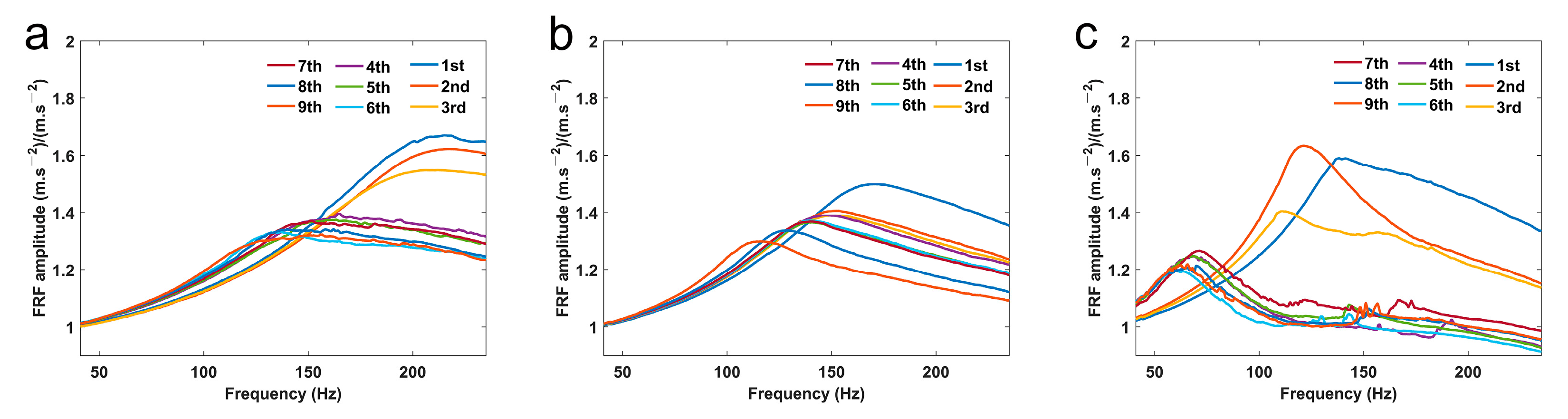
Figure 6 illustrates the experiment results of the frequency response function of the rubber isolator subjected to harmonic and random vibrations.
Figure 6a plots the result of the harmonic vibration FRF, in which the resonance peak value is reduced from around 220 Hz under a low excitation level to 110 Hz under a high excitation level.
Figure 6b indicates that as the power spectral density of the excitation increases, the resonant frequency at resonance decreases (from 80 Hz under low excitation to around 50 Hz), whereas the amplification factor of the amplitude shows a rising trend. The experimental results demonstrated that the rubber isolator demonstrated nonlinear stiffness and damping characteristics when it was excited.
According to the stiffness and damping algorithm scheme shown in
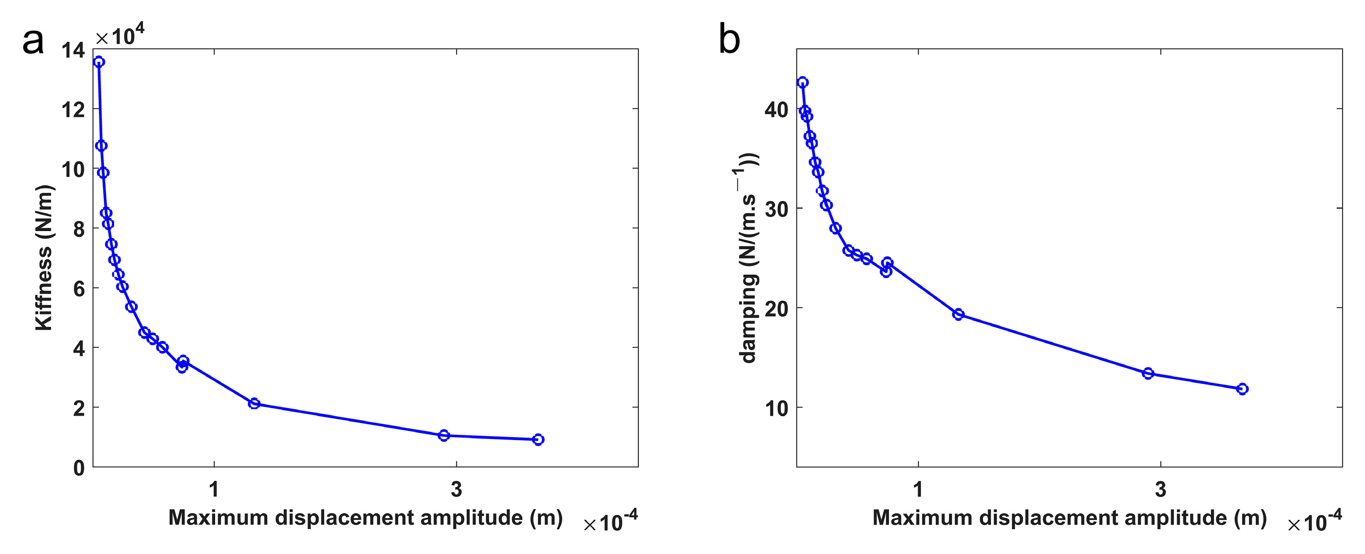
Figure 5, as well as the results of the harmonic vibration experiment, the relationship among nonlinear stiffness, nonlinear damping, and relative displacement amplitude can be established.
Figure 7 illustrates the nonlinear dynamic characteristics of the spherical rubber isolators. Notably, both stiffness and damping are negatively correlated with the displacement amplitude, and the correlation is nonlinear.
Figure 8 shows the sine frequency sweep results of the accelerated lifetime test when the load mass is [50, 60, 70] g. As indicated by the figure, for the accelerated lifetime test with constant load, the resonance peak value and the amplitude amplification factor show a downward trend as the random vibration repeats. The root-mean-squared value of acceleration can be calculated by Equation (9), which also shows a downward trend. In addition, as the load mass increases, the initial resonance frequency decreases.
In order to elucidate the fatigue lifetime decay of elastic rubber isolators with random vibration, the functions of the mean value of random acceleration and the stiffness decay of isolator stiffness were established.
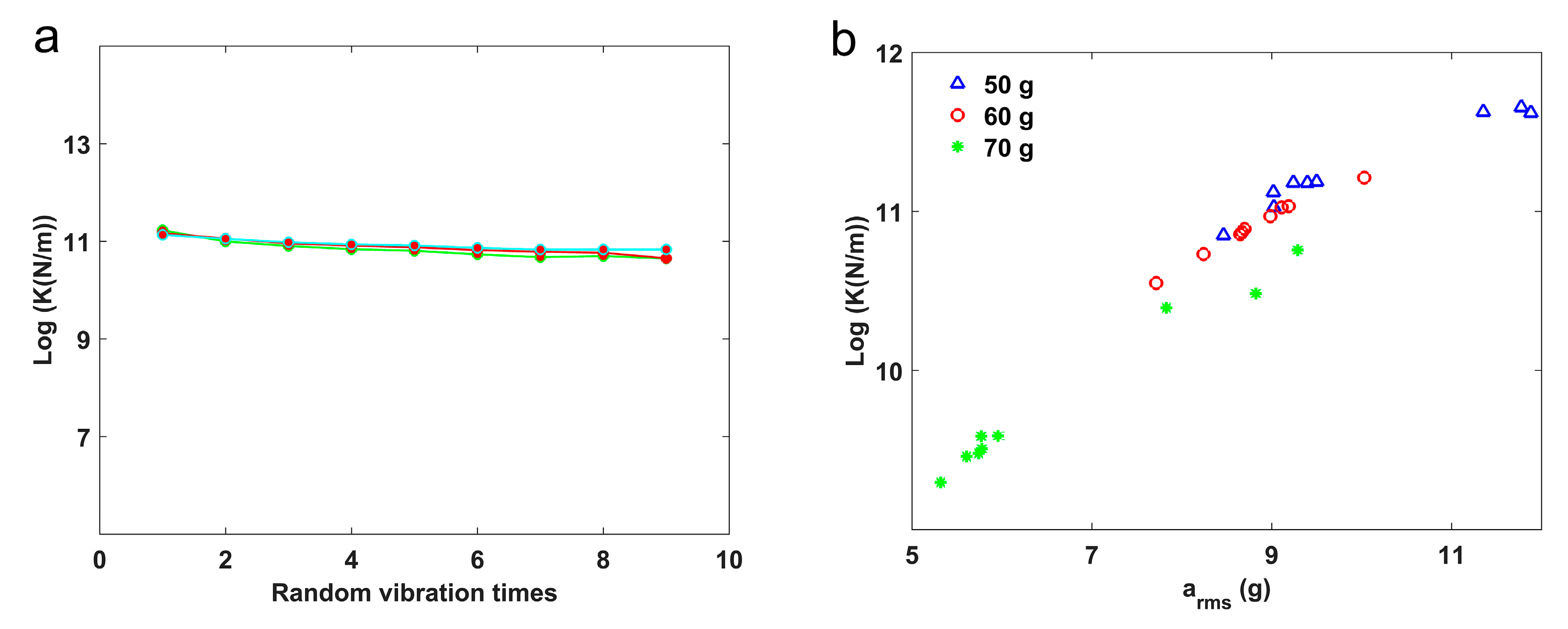
Figure 9a illustrates the results of repeated accelerated lifetime test when the load mass is 50 g, indicating that stiffness decreases as the time of the experiments increases. It is illustrated that under the same load mass, the stiffness decay of the rubber isolator remains basically the same every time a random vibration experiment is repeated. Therefore, the arithmetic mean value of the stiffness decay after each random vibration experiment of repeated experiments is calculated to represent the stiffness value corresponding to the acceleration mean value under the load. In the early stage of the accelerated lifetime test, the stiffness decreases significantly. As the random vibration experiment repeats, the stiffness declines stably. Finally, when the stiffness approaches the experimental cut-off threshold, the stiffness drops sharply.
Figure 9b shows that as the load mass increases, the isolator stiffness decreases even more. Notably, the stiffness value at the end of the experiment decreases, indicating that the load mass of the random vibration experiment produces a profound effect on the fatigue lifetime of the rubber isolator.
After the stiffness results of the experiment were converted into logarithm form, a correlation function relationship was established between the stiffness and the mean value of the random vibration acceleration [
16]. This correlation can be used to predict the fatigue damage of the rubber isolator. The polynomial function was used to fit the correlation between the stiffness and acceleration mean value. The equation is as follows:
Table 1 shows the coefficient fitting values under different loads and the Root-Mean-Squared Error (RMSE) calculated by Equation (10).
The RMSE represents the deviation between the predicted value of stiffness and the experimental test value. A smaller RMSE value demonstrates a more accurate stiffness prediction value. In this paper, the calculated RMSE value under different loads is very small, suggesting that the polynomial function fitting could decently predict the stiffness decay and evaluate the mechanical properties of the spherical rubber isolator.
5. Conclusions
In order to investigate lifetime of a thin-walled hollow spherical rubber isolator, firstly, vibration experiments of rubber isolators subjected to harmonic and random excitations were conducted in this paper. Then, by analyzing the mathematical model of the vibration isolation system, the approximate solution of the system root-mean-squared acceleration response and stiffness of the rubber vibration isolator based on random vibration was derived. Besides, dynamic experiments under random vibration loads were carried out to test the lifetime of the rubber isolator and describe its performance degradation. Furthermore, the correlation between the root-mean-squared acceleration response of the random vibration system and the stiffness decay of the rubber isolator was established, and a polynomial fitting was performed based on this correlation. The polynomial function of the simulation can be used to predict the lifetime of the rubber isolator. Meanwhile, the influence of the load mass on the lifetime of the rubber isolator was also investigated, suggesting a negative correlation between the load mass and the stiffness decay. These methods provide additional support for further practical engineering application of rubber damping systems.
Author Contributions
Conceptualization, H.L. and C.Y.; methodology, H.L.; software, S.W.; validation, P.S.; formal analysis, X.Z.; investigation, H.L.; resources, H.L.; data curation, H.L.; writing—original draft preparation, H.L.; writing—review and editing, H.L.; visualization, Z.P.; supervision, H.L.; project administration, Q.M.; funding acquisition, Q.M. All authors have read and agreed to the published version of the manuscript.
Funding
This research was funded by National Natural Science Foundation of China and the Foundation of State Key Laboratory of Applied Optics, Grant Number 11774342 and 61805238.
Institutional Review Board Statement
Not applicable.
Informed Consent Statement
Not applicable.
Data Availability Statement
The datasets used and/or analyzed during the current study are available from the corresponding author upon reasonable request.
Acknowledgments
This work was supported by the CAS Interdisciplinary Innovation Team, the Youth Innovation Promotion Association CAS and the National Hi-Tech Research and Development (No. 863) Program.
Conflicts of Interest
The authors declare no conflict of interest.
References
- Roncen, T.; Sinou, J.J.; Lambelin, J.P. Experiments and nonlinear simulations of a rubber isolator subjected to harmonic and random vibrations. J. Sound Vib. 2019, 451, 71–83. [Google Scholar] [CrossRef]
- Harris, J.; Stevenson, A. On the role of nonlinearity in the dynamic behavior of rubber components. Rubber Chem. Technol. 1987, 8, 553–577. [Google Scholar] [CrossRef]
- Bing, Z.; Qian-chao, L.; Kai, R. Study on the vibration performance of the single-layer rubber-like vibration isolating devices of the major turbine. China Shiprep. 2008, S1. Available online: http://111.44.140.226:81/KCMS/detail/detail.aspx?filename=ZGXC2008S1005&dbcode=CJFQ&dbname=CJFD2008 (accessed on 15 July 2021).
- Papoulia, K.D.; Kelly, J.M. Visco-hyperelastic model for filled rubbers used in vibration isolation. J. Eng. Mater. Technol. 1997, 119, 292–297. [Google Scholar] [CrossRef]
- Sjöberg, M.; Kari, L. Testing of nonlinear interaction effects of sinusoidal and noise excitation on rubber isolator stiffness. Polym. Test. 2003, 22, 343–351. [Google Scholar] [CrossRef]
- Richards, C.M.; Singh, R. Characterization of rubber isolator nonlinearities in the context of single- and multi-degree-of-freedom experimental systems. J. Sound Vib. 2001, 247, 807–834. [Google Scholar] [CrossRef] [Green Version]
- Ponnamma, D.; Sadasivuni, K.K.; Strankowski, M.; de Naers, P.M.; Thomas, S.; Grohens, Y. Interrelated shape memory and payne effect in polyurethane/graphene oxide nanocomposites. Rsc Adv. 2013, 3, 16068–16079. [Google Scholar] [CrossRef]
- Abraham, F.; Alshuth, T.; Jerrams, S. The effect of minimum stress and stress amplitude on the fatigue life of non strain crystallising elastomers. Mater. Des. 2005, 26, 239–245. [Google Scholar] [CrossRef]
- Mars, W.V.; Fatemi, A. Factors that affect the fatigue life of rubber: A literature survey. Rubber Chem. Technol. 2004, 77, 391–412. [Google Scholar] [CrossRef]
- Nilsson, J. Fatigue and Fracture of Elastomers. 1998, pp. 435–460. Available online: https://lup.lub.lu.se/student-papers/search/publication/3566495 (accessed on 10 July 2021).
- Eyo-Honesty, R.E.; Egbe; Evudiovo, P. Development of carbon fibre reinforced natural rubber composite for vibration isolation. In Proceedings of the IOP Conference Series: Earth and Environmental Science, University of Nigeria, Nsukka, Enugu State, Nigeria, 11–13 November 2020; Volume 730, p. 012016. [Google Scholar]
- Ming, S.Y.; Ying, H.; Ping, Z.G. Experimental study on the vibration isolation performance of metal-net rubber vibration absorber. Int. J. Mater. Metall. Eng. 2016, 10, 1157–1161. [Google Scholar]
- Tavar, J.; Grkman, G.; Duhovnik, J. Accelerated lifetime testing of reinforced polymer gears. J. Adv. Mech. Des. Syst. Manuf. 2018, 12, JAMDSM0006. [Google Scholar] [CrossRef] [Green Version]
- Berg, M. A non-linear rubber spring model for rail vehicle dynamics analysis. Veh. Syst. Dyn. 1998, 30, 197–212. [Google Scholar] [CrossRef]
- Tse, F.S. Mechanical Vibrations: Theory and Applications; Elsevier: Amsterdam, The Netherlands, 1978; pp. 322–325. [Google Scholar]
- Ao, H.; Ma, Y.; Wang, X.; Chen, J.; Jiang, H. Accelerated lifetime test of vibration isolator made of metal rubber material. In Proceedings of the IOP Conference Series: Materials Science and Engineering, Sanya, China, 19–21 November 2016; Volume 167, p. 012051. [Google Scholar]
| Publisher’s Note: MDPI stays neutral with regard to jurisdictional claims in published maps and institutional affiliations. |
© 2021 by the authors. Licensee MDPI, Basel, Switzerland. This article is an open access article distributed under the terms and conditions of the Creative Commons Attribution (CC BY) license (https://creativecommons.org/licenses/by/4.0/).


 ,
, 


