1. Introduction
High-performance computing (HPC) accelerates product development by decreasing the computing time of numerical-intensive simulations, such as CFD analyses, and allows for an increase in design iterations. Automating the simulation-driven optimization processes can further increase the efficiency of product development. However, utilizing HPC systems in this way requires specialist knowledge, dedicated hardware and comprehensive software licenses for proprietary simulation software. The monetary expenditure is easy to forecast but it is hard to determine the benefit regarding the time reduction of development cycles or the implications for the product’s quality. For that reason, HPC-driven product development is still a considerable cost factor for small and medium-sized enterprises (SMEs) with uncertain profitability.
In recent years, there has been a great deal of interest in outlining the advantages of HPC and automation for simulation and optimization processes. Thus far, comparatively few attempts have been made to measure their technical and economic effects on product development. Studying technical and non-technical effects of new technologies on existing systems and organizations is an important aspect of technology adaption and has already been addressed for similar fields, e.g., in [
1] for cloud computing.
The aim of this paper is to quantify the effects of HPC on product development, to make a case for future profitability calculations and to increase HPC’s acceptance among SMEs. Therefore, we used a case study approach and accompanied a formula student racing team over several seasons. We developed and implemented an HPC-driven optimization approach based on ANSYS Fluent and studied the team’s productivity before and after deploying HPC-based development procedures. We focused on the following questions:
- (1)
How many major design iterations can be conducted in a predetermined period with the help of HPC and automation compared to the conventional approach of not utilizing HPC (quantitative effect)?
- (2)
How does the quantitative effect affect the product’s key performance indicators (qualitative effect)?
This article is structured as follows: First, we give a brief insight into product development to underline the relevance and analyze the challenges and requirements when setting up an automated and HPC-based development process. In
Section 2, we describe brief theoretical foundations of parallel processing, present the investigated case and the details of the implemented and HPC-based design optimization approach.
Section 3 then moves on to present the results of the HPC adoption for the investigated case. In
Section 4, we discuss those results and assess the implications for product development aided by HPC. Finally, we summarize our work and evaluate the case study critically.
1.1. Background
The complexity of product development is constantly increasing due to more disciplines being involved, such as mechanics, electrical engineering and information technology. For managing the interdisciplinary nature of product development, the approach of systems engineering (SE) has been developed over the years and established in both academia and industry [
2]. The basic idea is to subsequently reduce complex systems into smaller and more manageable subsystems and define their interfaces in advance [
3,
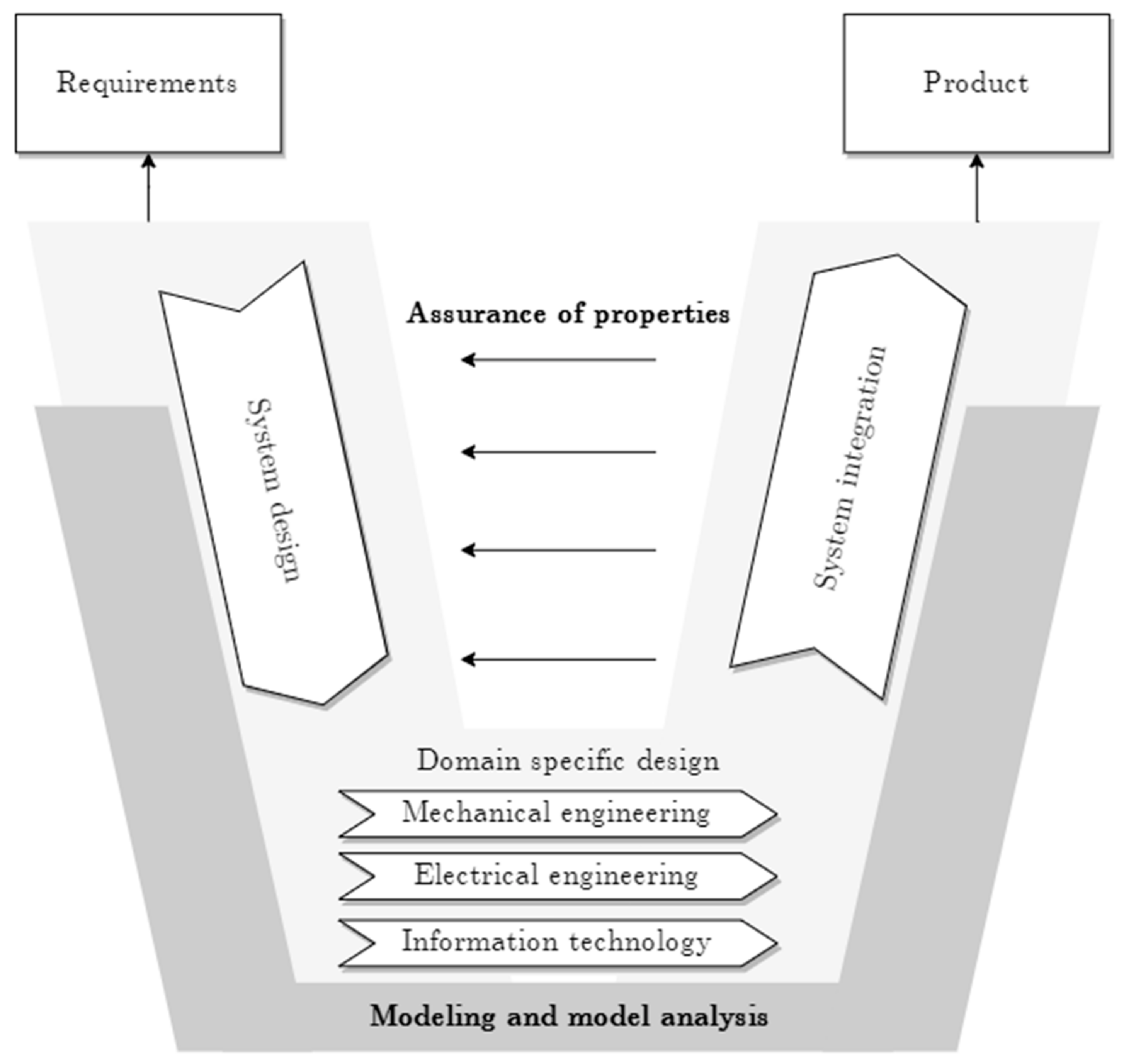
4]. A widely used SE model is the V-model (see
Figure 1), which classifies the technical work stages in product development processes and defines responsibilities. One of the first works addressing product development according to the V-model was published in 1991 [
5]. However, the model has been adapted in multiple ways, and enhanced and implemented in guidelines, such as VDI 2206 [
6], which is widely used in German-speaking countries.
According to VDI 2206, product development begins with the requirements specification in the left branch of the “V” and is continuously enriched and detailed until the requirements for all subassemblies and components are specified and a final design is available (lower tip of the “V”). The right branch covers the validation and verification of the design proposals. For example, simulations or bench tests validate the required properties on the different abstraction levels. In this context, it is essential to consider the dependencies between the (sub)systems. In addition to straightforward validation, one must also successfully carry out integration tests in the higher-level system structure. The right branch usually concludes with a simulation of the overall system. If one of the tests fails and components must be modified or optimized, this leads to new validation and verification test cycles [
7]. In simulation-based product development, this results in a large number of simulations, which, depending on the type of analysis, can result in a high computing load, especially if many engineering disciplines are involved, as is now common. If product development includes very elaborate simulations, such as computational fluid dynamics (CFD), single simulations can already be so time-consuming that only a few designs or optimization iterations for the overall system are possible to meet a given time-to-market. Reducing the accuracy of simulation models to save computational load is not worthwhile in many use cases. Especially for iterative developments, the use of high-resolution simulation models is beneficial, as shown, for example, in [
8].
Possibilities to speed up complex simulation-based development processes are the increased use of HPC systems to accelerate simulations, the automation of simulation and optimization processes or a combined approach. Unfortunately, the automation of optimization processes highly depends on the underlying model and is usually associated with a high initial effort. In [
9], for example, an approach to an automated CFD-based optimization is shown. With the rapid increase in performance of processor and memory technologies and current research in the HPC domain [
10], further increases in efficiency and cost reductions are highly probable. Combined with progressive development of computational methodologies [
11,
12], this opens new potential for product development [
13].
Unfortunately, the tendency of SMEs to use HPC is low. This is partly due to the comparatively high cost and knowledge required to integrate HPC into existing processes and the poor quantifying value of HPC for SMEs. We want to address the last obstacle by providing insights in HPC-based product development to show its effects and value. However, first, we will examine the challenges of integrating HPC in the following subsection, focusing on an automated CFD workflow as an example.
1.2. Challenges and Requirements
In this subsection, we examine challenges that need to be handled to set up an automated CFD optimization workflow on HPC systems. However, before we proceed, some necessary definitions and explanations for the rest of the article are provided. HPC systems can exist in various forms and their size can vary between local clusters or large-scale supercomputers, which can either have virtualized or non-virtualized resources. In order to maximize performance, we define an HPC system in the context of this article as a system with dedicated and distributed memory hardware. The available resources (hardware and software licenses) usually cannot cover the computing needs, which realistically reflects many SMEs’ situations. This requires the usage of scheduling systems, which orchestrate the resource allocation for a set of given jobs submitted by one or more users working for multiple teams. A job is a specific computation for the HPC system. This can either be a single flow simulation or parametric optimization of a CFD simulation, involving several runs with varying design variables. The set of all sequential or parallel jobs for a given simulation model defines a workflow. When implementing an automated workflow for CFD simulation, several challenges can occur:
Since resources (hardware and licenses) are usually limited, one has to determine the optimal computation configuration for the given job depending on the flow model.
Asynchronously sent jobs have to be integrated into the overall workflow.
Automated postprocessing must be conducted on the HPC system in order to save data bandwidth.
Less experienced IT users must be able to interact with the implementation of the process.
In order to use HPC cost-effectively in product development, one has to consider these challenges during the implementation of HPC-supported optimization processes in an organization. This leads to the following requirements for its implementation:
Usability: The implementation should be usable without in-depth knowledge of the underlying CFD solver and HPC system.
Efficiency: The overall runtime of a simulation should be reduced as much as possible. Therefore, the optimum hardware shall be considered for each particular case and the amount of data exchanged from local host to the HPC system shall be reduced as much as possible.
Portability: The implementation should be adaptable for any (parametric) flow model and should be re-usable on a different HPC system with as little modification as possible.
Automation: Steps that are time-consuming or error-prone should be automated where reasonable to achieve a certain level of automation and to guarantee absolute comparability. This leads to a more time-efficient development process and simultaneously increases its robustness.
Physical accuracy: The obtained results should be of high quality and accuracy. Therefore, the user must be able to change most of the physical preferences via a text file-based interface to allow variance in parameters within one workflow.
2. Materials and Methods
In this section, all theoretical and practical foundations, throughout this contribution, are introduced as much as is necessary to reproduce or evaluate the results. This includes a brief introduction to CFD workflows, the fundamentals of parallel computing and a presentation of the research design, as well as the utilized software and HPC system.
2.1. CFD Workflow
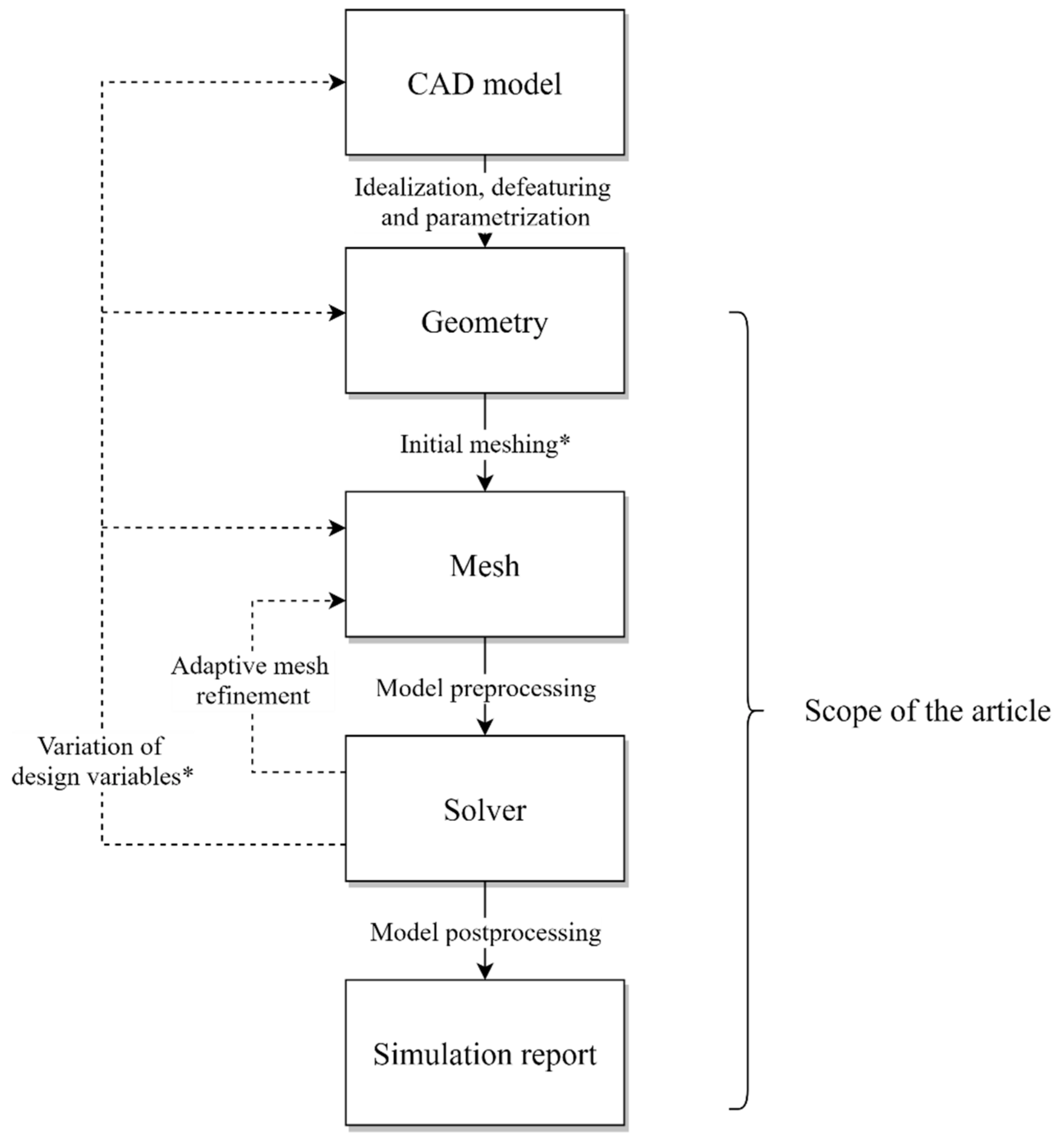
As shown in
Figure 2, a CFD workflow implies setting up an initial design (CAD model), deriving an idealized and defeatured geometry (geometry), its discretization (mesh), the computation (solver) and a report to evaluate the simulation results. During a product’s optimization, several of the model parameters (design variables) are usually varied systematically and thus a large number of simulations are generated. However, since changes to the geometry require new meshing, the simulation procedure described so far might be repeated for each design iteration. If the model is parametrized, the variation in design variables and the restart of the downstream process steps can be automated. Since an automation of the overall optimization process results in a multitude of simulations, it is appropriate to utilize HPC systems.
The variation in the design variables can be applied on different levels: They can affect the mesh, the idealized geometry or the original CAD model. It is advantageous to apply design variables to the CAD model if the optimized design is to be available as a CAD model after completion of the optimized design. However, this implies a significantly higher computing effort per design iteration and an increasing amount of data to be transferred between a local host and the remote HPC system. Therefore, the scope of our article focuses on applying design variables only to the simulation model (geometry and mesh as depicted in
Figure 2).
Within the case study, there are slight limitations regarding the degree of automation: Since the approximation of the geometry and fluid domain is crucial for the validity of the results, the initial meshing requires manual user interaction for an assessment of the mesh quality. Although there are well-established mesh quality metrics, which indicate an overall quality and show starting points for mesh improvement, no computer can say whether the quality is sufficient or not without having in-depth knowledge about the context of the simulation. Therefore, we assume that the initial mesh has already been verified and potential adaptive mesh refinement on the verified mesh does not negatively influence the obtained results.
2.2. Foundations of Parallel Processing
In order to rate parallel performance and advantages, several fundamental laws of parallel computing have to be introduced. The first one is so-called Amdahl’s argument [
14]. In its most basic form, it describes how the overall elapsed time of a parallel program is composed. It is defined as:
where
is the overall time,
is the number of CPUs,
is the time to run the sequential part and
is the time to run the parallel part. Therefore, a serial run of the program can be expressed by
while the serial fraction of the program’s code
is defined as
Applying these definitions to the first equation leads to, namely
Then, the overall speedup of parallel computation can be defined as
In summary, Amdahl’s argument gives the upper limit of possible speedup in parallel computing if the problem size is fixed. This condition can appear as a bottleneck of this theory, so Gustafson’s law [
15] was proposed. The new theory not only addresses the issue of fixed problem sizes, it also promotes strict linear speedup for the parallel part while the serial part is kept constant. In brief, Gustafson’s law describes the possible speedup for cases where the ratio of problem size and resources is kept constant. Both theories are now widely accepted and are considered to be legitimate but have different points of view. Amdahl’s law is known as strong scaling while the Gustafson’s law is referred to as weak scaling. To avoid any possibility of confusion, the speedup defined by Gustafson’s law is today known as scaled speedup [
16]:
It is important to note that performance benchmarking should not be considered trivial. In particular, benchmarking with heterogeneous HPC resources requires special approaches, as indicated in [
17].
2.3. The Case: Elefant Racing
In this section, we present the object of our study, the formula student team Elefant Racing (University of Bayreuth, Germany), in more detail. Formula student racing is a competition for engineering students. Every year, the teams develop a new racing car and compete against each other. Our institute supports students by providing infrastructure and knowledge. To be successful, a team must engage in research, manufacturing and testing, in addition to designing the racecar.
Furthermore, the teams must also deal with marketing, finance and management issues. Therefore, Elefant Racing can also be regarded as a small company. Considering the team’s usually very small financial resources, cost efficiency is probably a much more significant factor than in actual companies. Thus, Elefant Racing is an ideal candidate to study the benefits of automated HPC-based development processes.
Each season, the formula student team designs a new racecar from scratch. Up to now, the students have carried out their simulations and optimizations on conventional workstations with the known limitations about computational power and capacity. In the context of our research, we opened our HPC infrastructure to the team, provided methodological knowledge and conducted the implementation. This was the first time that the team was able to perform a CFD simulation of the entire racecar. Previously, only specific parts had been investigated aerodynamically, therefore HPC opened up new possibilities in terms of holistic optimization. Their development workflow was similar to [
18]. Since our institute supported and guided Elefant Racing for several years, the team’s efficiency increase through HPC could be quantified by comparing historic key performance indicators (KPIs) with today’s: “drag” and “downforce”. Drag is the force that a surrounding fluid exerts on an object in motion. The smaller the drag, the more efficient the movement of the racecar. In contrast, downforce is a vertical force in the racecar acting perpendicular to the road in addition to the racecar’s gravitational force. A high downforce is generally desirable because it leads to higher friction between the tire and the road, thus enabling higher cornering speeds. Therefore, the team’s objective is always to minimize drag while maximizing downforce.
2.4. Software and Hardware Stack
Within the case study, all simulations were conducted with ANSYS Fluent v19.2. Besides the graphical user interface (GUI), ANSYS Fluent provides a scheme-based text interface (TUI) for automation of tasks. Scheme is a LISP dialect. For details, we refer the reader to [
19,
20].
We utilized the HPC system “btrzx4” with a total number of 91 compute nodes. Most nodes were equipped with two Intel Xeon E5-2630 v4 @ 2.2 GHz (Broadwell), resulting in a total of 20 physical CPU cores per node. We refer to those nodes as “compute20”. Some of the nodes had additional memory (2x 128 GB RAM) and a GPU (NVIDIA Tesla P100, 12 GB), which we refer to as node type “cuda”. There were other node types available, but compute20 and cuda were the most beneficial nodes for CFD analysis in the available HPC system.
The interconnection between the nodes was a two-level fat-tree Intel Omni-Path network. This network is a particular optical fiber network for HPC systems, designed for high parallel bandwidth and low parallel latency. The Omni-Path technology is similar to the open industry standard Infiniband with connection speeds up to 100 Gib/s [
21]. The network throughput of the HPC system reached around 6.259 Gib/s within ANSYS Fluent, while the network latency was, on average, 1.598 µs. The operating system was CentOS version 7. As a resource manager and scheduler, we used PBS Torque in combination with Maui. At the time of the research, there were no restrictions on the wall time for team members of Elefant Racing.
2.5. Implementation
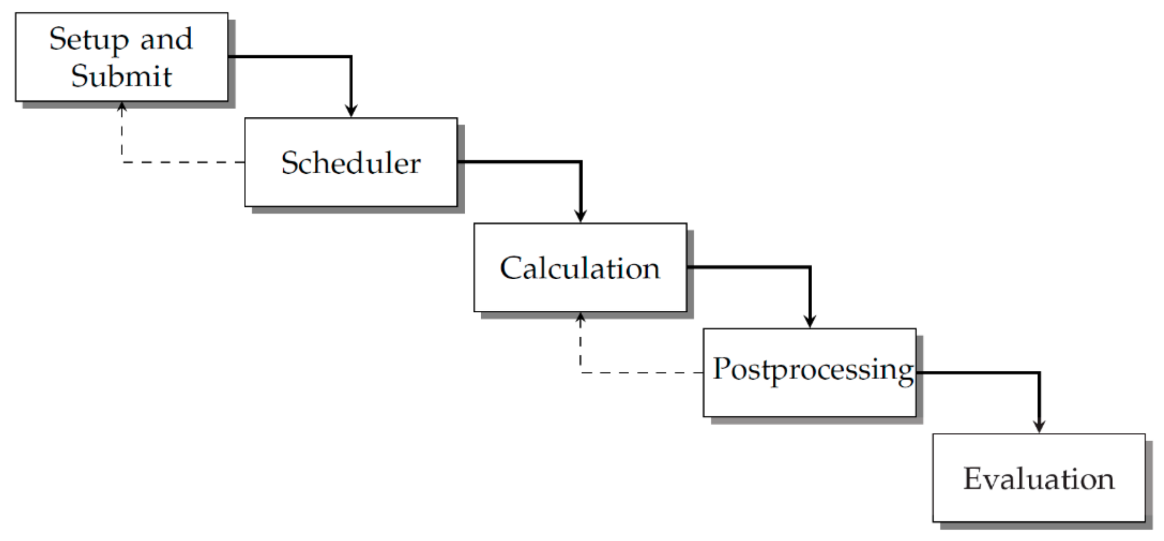
In this subsection, we present the implementation details of the HPC optimization procedures. First, an automated CFD simulation had to be modeled into the schema presented in
Figure 3, which consists of five basic stages. This also represents the structure of the implemented code, as there was one individual script for each of these steps. Within
Figure 3, the dotted lines indicate two potential loops where variation of model parameters is possible by changing values within the CFD application or by asynchronously submitting additional jobs.
Within the Setup and Submit stage, all required settings, both the model and HPC job-related parameters, are parsed from separate text files where the user can modify the iteration according to the user’s preferences. This will already include an automatic allocation of HPC resources based on a decision rule, which must be defined in advance. A commonly used approach reinforces the decision rule by individual benchmark results. CFD parameters like turbulence modeling can be set up in the files as well. Furthermore, the user has to specify a threshold value for the desired residuals and maximum number of iterations. At the end of the step, the script submits the job to the HPC system’s queue, invokes the HPC system’s scheduler and precisely defines the application and the data which the CFD solver should execute. In the Calculation phase, the logic and the internal solver data are defined and executed. If the residuals do not fall short of the threshold and the solver exceeds the maximum number of iterations, the workflow terminates itself automatically and frees HPC resources for other runs of the optimization loop and/or other users. For many cases, especially within parameter studies, a standardized approach for Postprocessing with predefined figures and views can already be of huge value. This not only reduces the amount of data which have to be transferred from the HPC system to a local host, where postprocessing is often conducted, it also reveals the areas to examine further within the optimization process. Last, in the Evaluation phase, all runs are summarized in a pre-defined report and can include different metrics based on the user’s preferences. The presented schema presumes a high-quality mesh, as already discussed in the previous section. If there is no optimization process and the CFD simulation is run only once, there is no considerable benefit in automation and there would not be any loop iteration. However, if the user wants to conduct a parameter or optimization study with constant HPC resources, the Calculation and Postprocessing phases can be executed in a loop and the simulation is run within the same instance of the CFD software several times. Furthermore, the user can submit multiple jobs asynchronously. This might be beneficial if additional resources become available or the user wants to achieve additional parallelization.
Using the Scheme interface, automation of tasks within ANSYS Fluent is achievable. During programming, we encountered the issue that the interface does not rest upon a clear standard and can be seen as a mixture of MIT Scheme 3 and 4. In the example below (Algorithm 1), the TUI command, which is double-quoted, would start a simulation run with the value previously assigned to number-of-iterate. Additionally, these exact strings could be entered into the GUI console to start the simulation. The command would be executed for any value within the list called speed-parameters due to being nested in a Scheme for each loop.
| Algorithm 1. Exemplary code snippet for calling ANSYS Fluent with dynamic parameter passing using TUI and Scheme interface. |
(for–each (lambda (air–speed)
(begin
;–––Run calculation–––
(ti–menu–load–string (format #f “solve iterate number–of–iterate”))
)
) speed–parameters) |
Consequently, we recommend a text editor which is capable of interpreting the LISP-specific syntax of s-expressions. As a result, it is only possible to test implementations on specific simulation input files, preferably on the system used later.
The idea of an automated setup also includes the intention to optimize the overall runtime and resource utilization. Therefore, the selection of hardware resources in proportion to the problem size (internal degree of freedoms) is a critical variable since it is one of the few options to affect the overall runtime within proprietary simulation software. However, scaling is highly specific to hardware, software and the model itself. Usually, in many commercial CFD simulations, one process per CPU core is spawned, resulting in a model-dependent cell-per-CPU ratio. This ratio has a high impact on the speedup since it influences the wall time per iteration. We have benchmarked ANSYS Fluent 19.2 and listed the average wall time per iteration in
Table 1. The lower the avg. wall time per iteration, the shorter the overall runtime. Based on the benchmark results, we implemented an HPC resource allocation rule on the ratio.
Most simulation software packages require so-called license tokens. For each CPU core used, a certain number of license tokens is required. Within the case study, the formula student team had licenses to utilize 300 CPU cores in total, consequently resulting in a threshold of 45 million cells which could be processed in the HPC system simultaneously. Since there are no restrictions on hardware resources and other limiting factors, such as memory size, did not have an influence, the licenses can be seen as the major bottleneck in scalability for both the development workflow and the speedup of the solver itself.
3. Results
After describing the implementation of the automated CFD process on HPC systems in the previous section, this section will present the implications for product development.
The scope of our research subject included a “real-world” application in which the aerodynamic package of a formula student open-wheel racing car was redesigned from scratch. A formula student team as an object of research is particularly interesting because there are short development cycles and often fewer restrictions compared to most industrial projects, which opens new possibilities for innovations based on high-fidelity CFD simulations. By using HPC, the formula student team was able to implement an automated optimization approach for the aerodynamics of their racing car. It was not possible for the Elefant Racing team to implement such an approach before due to the lack of computational resources.
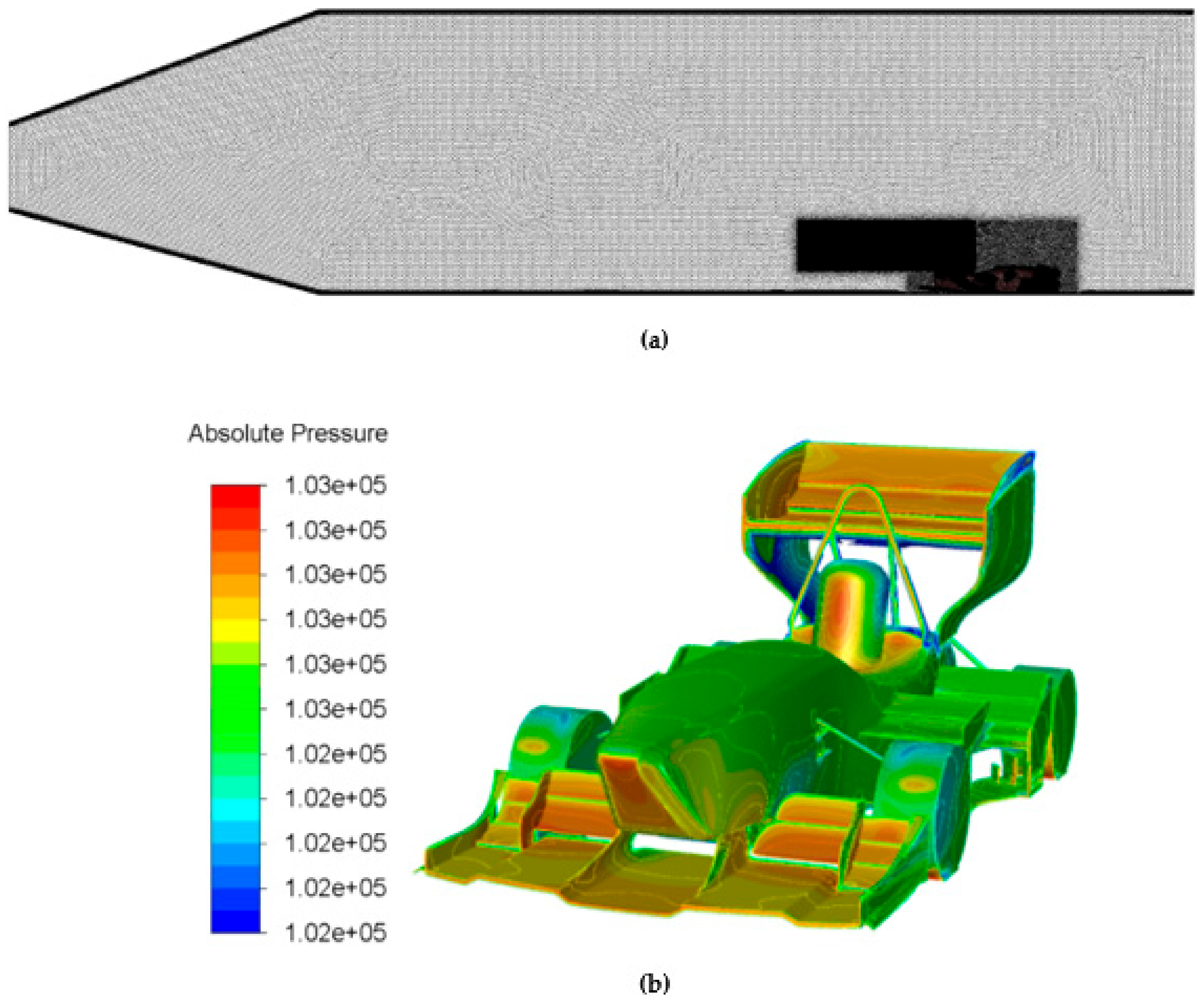
Before applying the workflow to the open-wheel racing car, a symmetric full-scale CFD simulation had to be set up in order to verify the initial mesh quality. The basis of the CFD model was CAD geometry in which all aerodynamically unnecessary elements (e.g., bolts, nuts) were removed. The surrounding fluid domain was meshed with polyhedrons including two refinement boxes to capture the recirculation zone. The fluid domain had a relatively large size compared to the racecar in order to minimize any unphysical impact of uniform boundary conditions. The resulting CFD model consisted of approx. 80 million mesh cells and was set up with a double precision, pressure-based 3D solver. Both laminar and turbulent cases were investigated. Exemplary insights into the model and results are shown in
Figure 4a,b.
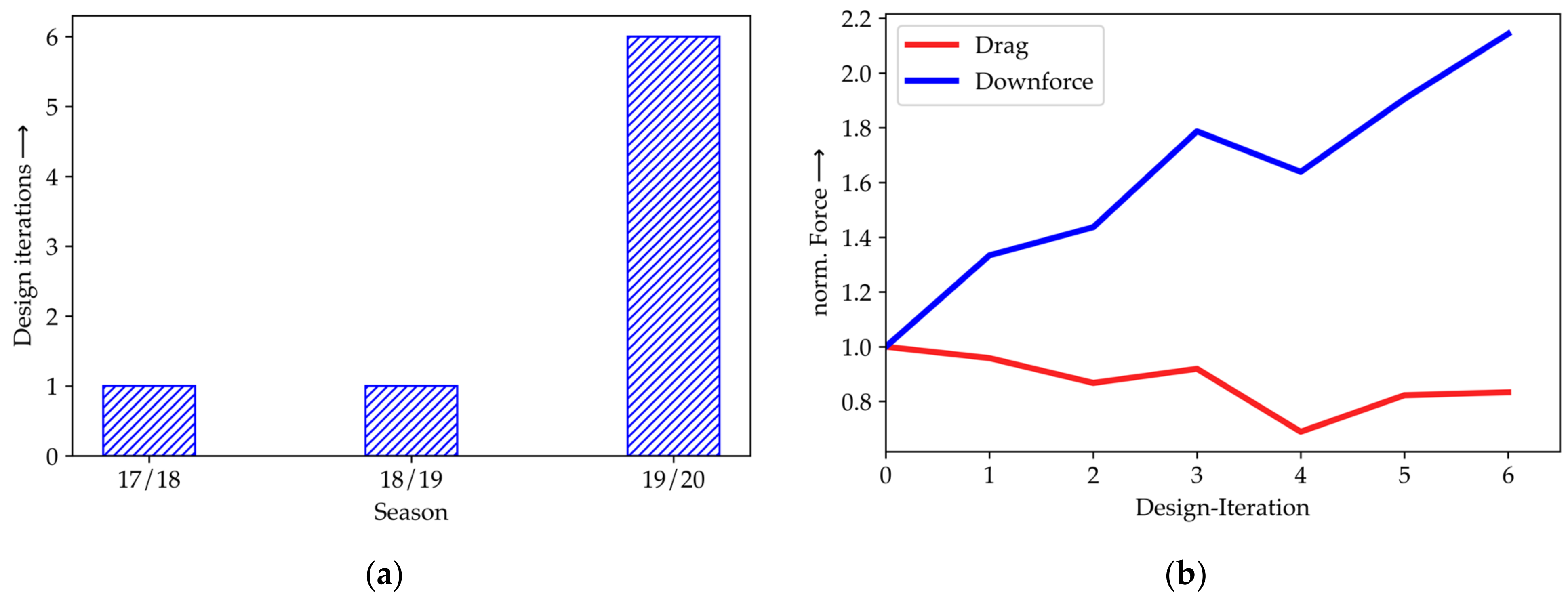
The effect of HPC on the efficiency of Elefant Racing’s product development can be illustrated by comparing the number of major design iterations to the previous years and by showing the progress within the season where the implementation is used for the first time (season 19/20). Thereby, major design iterations are defined as adding new parts or changing parts for fully redesigned versions. In contrast, changing positions or sizes of parts was conducted within an iteration. Therefore, there were up to 100 simulations within one single design iteration. The number of designs iteration before and after the availability of HPC is shown in
Figure 5a. Furthermore, HPC leads to major design improvements, as the KPIs drag and downforce indicate in
Figure 5b.
The use of an HPC-based and automated CFD setup increased the number of design iterations by 600%.
Figure 5b reveals more details of season 19/20 when the new approach was used for the first time: Within this season, a significant increase in downforce by about 115% was achieved while the drag force was reduced by about 20% during the optimization workflow. It is also worth considering that the overall performance gain would have been far less after one iteration in this particular year. The graphs also show setbacks throughout the development process which can lead to even better results or are easier to cope with. This opens the opportunity to explore designs that are even more experimental.
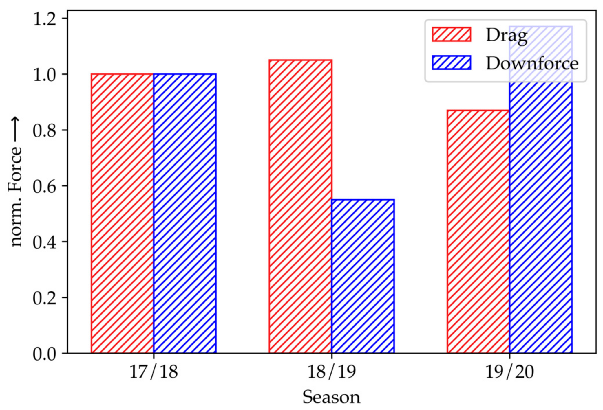
Figure 6 shows the drag and downforce KPIs of the final racecar designs for the last three seasons. Compared to the previous season 18/19, downforce increased in 19/20 by 214% and drag was reduced by 17%. Since optimizations on the basis of full-scale simulations on the entire racecar were first enabled with HPC in season 19/20, setbacks of initial designs in previous seasons could hardly be improved. For example, the racecar of the season 18/19 was worse than the design in 17/18 due to missing computational power and the remaining time budget.
HPC has also changed the way team members work.
Table 2 shows the estimated time spent on the individual phases of the development workflow of a new design before and after HPC introduction. The reduction in waiting times, the elimination of the manual modification of design variables or the generation of reports allows a stronger focus on value-adding activities such as model development or testing. However, as a precaution, we would like to emphasize that this is merely a shift in expenditure. The time required to generate valid meshes, to verify and validate models, etc. is only being moved from the day-to-day operations to the implementation and deployment phase of the HPC optimization approach. However, this shifting leads to shorter development cycles and can increase the internal capability of an organization’s R&D unit. Despite the high initial effort for such an approach, HPC and the ability to derive and implement adjustments or optimizations quickly can still be seen as a major competitive advantage, both on the product side and economically.
4. Discussion
Due to HPC, the formula student team increased the major KPI downforce up to 115% while also decreasing drag force by about 20% within one project lifetime or a formula season. However, there is still a lot to consider towards reasonable handling of HPC-based optimization procedures. The degree of automation and the costs of hardware and software licenses (if one is using proprietary software) must be weighed up accurately. For the iterative development of a single and parameterizable product, the approach shown is suitable since the initial implementation effort can be quickly amortized. However, if one conducts simulation not on a regular basis or uses simulation software in a more general manner on different products, such an implementation might be disproportionate.
The most significant restriction on HPC-based product development is probably the automation of mesh generation. Since meshing can be considered as a critical, time-consuming and complex step, which can heavily affect the quality of results, the possible degree of automation is limited and considered a major bottleneck [
22]. Current mesh automation approaches such as conducting mesh generation and manipulation on an HPC’s “super node” are widely considered unpractical, especially for high-fidelity meshes [
23], and lack acceptance. Although the meshing process can benefit from automation, user interaction is still needed for preparing geometry, choosing proper cells or improving the mesh’s quality. Even with current defeaturing methods and adaptive mesh refinement, preparing the initial mesh generation remains one of the most time-consuming steps throughout the CFD process and highly depends on specialist knowledge and experience. Therefore, complete automation is neither currently possible nor reasonable, as argued.
Besides mesh generation, the CFD process does benefit from automation on HPC systems. The reason for that is that these problems are solved by sophisticated software, which typically has a time-consuming set up phase that rarely differs throughout the development of a specific product.
Several studies (e.g., [
24]) state that CFD solvers can also benefit from general-purpose computation on GPU (GPGPU) acceleration in principle. However, we could not confirm a significant effect. Although the manufacturer of the GPUs of the “cuda” nodes cooperates with the software vendor and advertises possible speedup factors up to 3.7 [
25], we could not achieve such a significant speedup by the use of GPGPU acceleration. It turns out that these high speedups are limited to particular cases, physical preferences and machines with a considerably high number of GPGPUs, which might lead to bad cost–benefit ratios. Unfortunately, this fact is not self-evident, and a bit misleading since the official user guide for graphic-accelerated runs only states a comprehensive formula to calculate the maximum mesh size. Consequently, no overall statement on the effect of GPGPU acceleration can be made but GPGPU acceleration is still a promising current trend towards increasing the overall performance of HPC systems and should always be considered.
It is clear that CFD simulations are not an end in themselves and require a lot of expertise. However, the latest developments in artificial intelligence (AI) and machine learning can assist the user further in the future. Current research shows that AI can already support the generation of problem-adapted geometries and models [
26]. The evaluation of the mesh quality, which is now mostly conducted by the user, could also be automated with the help of AI [
27]. The practical applicability of AI-based meta-modeling is also continuously increasing [
28], making AI a promising perk for the HPC and simulation-driven product development of the future.
Whether with or without AI support, high-performance computing and automation enable organizations to fundamentally speed up and improve their product development processes. This not only results in more design iterations in less time, but also in a solid increase in the product’s performance and/or quality, as indicated by our case study.
Of course, the general validity of the results is limited, since the subject of the study was a formula student racing team. Therefore, the results need to be verified with real company data. However, considering the usually small data basis in this research field due to their sensitivity and most companies’ healthy skepticism about revealing them, this article still proves the positive effects of HPC for product development and indicates that a combination of HPC and automation is beneficial for product development. Therefore, this research can serve as a reference and help to facilitate the acceptance of HPC and automation, especially among SMEs.
Author Contributions
Conceptualization, C.L.; methodology, C.L.; software, P.B.; validation, C.L., P.B. and T.R.; formal analysis, C.L. and T.R.; investigation, C.L., P.B. and T.R.; resources, S.T. and F.R.; data curation, C.L. and P.B.; writing—original draft preparation, C.L. and P.B.; writing—review and editing, C.L., T.R. and S.T.; visualization, T.R. and C.L.; supervision, S.T.; project administration, S.T. and F.R.; funding acquisition, F.R. All authors have read and agreed to the published version of the manuscript.
Funding
The research is funded by the European Social Fund (ESF) and the Oberfrankenstiftung within the project HiPerSim4all (StMBW-W-IX.4-6-171193). This publication was funded by the German Research Foundation (DFG) and the University of Bayreuth in the funding program Open Access Publishing.
Institutional Review Board Statement
Not applicable.
Informed Consent Statement
Not applicable.
Data Availability Statement
The data presented in this study are available on reasonable request from the corresponding author.
Acknowledgments
The authors gratefully acknowledge the continuous support of the Research Center for Scientific Computing at the University of Bayreuth. The authors also pay special regards to Thomas Rauber and Matthias Korch from Applied Computer Science (University of Bayreuth), Etienne Pudell from Daimler AG and Elefant Racing e.V for their support.
Conflicts of Interest
The authors declare no conflict of interest. The funders had no role in the design of the study; in the collection, analyses, or interpretation of data; in the writing of the manuscript, or in the decision to publish the results.
References
- Maresova, P.; Sobeslav, V.; Krejcar, O. Cost–benefit analysis—evaluation model of cloud computing deployment for use in companies. Appl. Econ. 2017, 49, 521–533. [Google Scholar] [CrossRef]
- Pahl, G.; Beitz, W.; Blessing, L.; Feldhusen, J.; Grote, K.-H.; Wallace, K. Engineering Design. A Systematic Approach, 3rd ed.; Springer London Limited: London, UK, 2007. [Google Scholar]
- Wasson, C.S. System Engineering Analysis, Design, and Development: Concepts, Principles, and Practices, 2nd ed.; Wiley Series in Systems Engineering and Management; Wiley Blackwell: Chichester, UK, 2016. [Google Scholar]
- Walden, D.D. (Ed.) INCOSE Systems Engineering Handbook: A Guide for System Life Cycle Processes and Activities. In International Council on Systems Engineering, 4th ed.; Wiley: Hoboken, NJ, USA, 2015. [Google Scholar]
- Forsberg, K.; Mooz, H. The Relationship of System Engineering to the Project Cycle. INCOSE Int. Symp. 1991, 1, 57–65. [Google Scholar] [CrossRef]
- German Guideline VDI/VDE 2206:2020-09-E (2020): Design Methodology for Mechatronic Systems. VDI/VDE-Gesellschaft Mess- und Automatisierungstechnik. Available online: https://www.vdi.de/richtlinien/details/vdivde-2206-entwicklung-cyber-physischer-mechatronischer-systeme-cpms (accessed on 2 March 2021).
- Salehi, V.; Wang, S. Using Point Cloud Technology for Process Simulation in the Context of Digital Factory based on a Systems Engineering integrated Approach. In Proceedings of the 21st International Conference on Engineering Design (ICED17), Vancouver, BC, Canada, 21–25 August 2017; pp. 11–20. [Google Scholar]
- Kieffer, W.; Moujaes, S.; Armbya, N. CFD study of section characteristics of Formula Mazda race car wings. Math. Comput. Model. 2006, 43, 1275–1287. [Google Scholar] [CrossRef]
- Si, Q.; Lu, R.; Shen, C.; Xia, S.; Sheng, G.; Yuan, J. An Intelligent CFD-Based Optimization System for Fluid Machinery: Automotive Electronic Pump Case Application. Appl. Sci. 2020, 10, 366. [Google Scholar] [CrossRef] [Green Version]
- Dongarra, J.; Grigori, L.; Higham, N.J. Numerical algorithms for high-performance computational science. Philos. Trans. R. Soc. A Math. Phys. Eng. Sci. 2020, 378, 20190066. [Google Scholar] [CrossRef] [PubMed] [Green Version]
- He, F.; Dong, X.; Zou, N.; Wu, W.; Zhang, X. Structured mesh-oriented framework design and optimization for a coarse-grained parallel CFD solver based on hybrid MPI/OpenMP programming. J. Supercomput. 2019, 76, 2815–2841. [Google Scholar] [CrossRef]
- Nguyen, M.T.; Castonguay, P.; Laurendeau, E. GPU parallelization of multigrid RANS solver for three-dimensional aerodynamic simulations on multiblock grids. J. Supercomput. 2018, 75, 2562–2583. [Google Scholar] [CrossRef]
- Klippert, M.; Marthaler, F.; Spadinger, M.; Albers, A. Industrie 4.0—An empirical and literature-based study how product development is influenced by the digital transformation. Procedia CIRP 2020, 91, 80–86. [Google Scholar] [CrossRef]
- Amdahl, G.M. Validity of the single processor approach to achieving large scale computing capabilities. In Proceedings of the Spring Joint Computer Conference, Atlantic City, NJ, USA, 18–20 April 1967; ACM Press: New York, NY, USA, 1967; p. 483. [Google Scholar]
- Gustafson, J.L. Reevaluating Amdahl’s law. Commun. ACM 1988, 31, 532–533. [Google Scholar] [CrossRef] [Green Version]
- Padua, D. Encyclopedia of Parallel Computing; Springer: Boston, MA, USA, 2011. [Google Scholar] [CrossRef]
- Reguly, I.Z.; Mudalige, G.R. Productivity, performance, and portability for computational fluid dynamics applications. Comput. Fluids 2020, 199, 104425. [Google Scholar] [CrossRef]
- Mansour, H.; Afify, R.; Kassem, O. Three-Dimensional Simulation of New Car Profile. Fluids 2020, 6, 8. [Google Scholar] [CrossRef]
- Steele, G.L., Jr.; Sussman, G.J. Scheme. Available online: https://groups.csail.mit.edu/mac/projects/scheme/ (accessed on 8 February 2021).
- Dybvig, R.K. The Scheme Programming Language: ANSI Scheme; Prentice Hall: Upper Saddle River, NJ, USA; London, UK, 1996. [Google Scholar]
- Intel Corporation. Intel® OPA Performance. 2020. Available online: https://www.intel.de/content/www/de/de/high-performance-computing-fabrics/omni-path-architecture-performance-overview.html (accessed on 8 February 2021).
- Slotnick, J.; Khodadoust, A.; Alonso, J.; Darmofal, D.; Gropp, W.; Lurie, E.; Mavriplis, D. CFD Vision 2030 Study: A Path to Revolutionary Computational Aerosciences; National Aeronautics and Space Administration (NASA): Washington, DC, USA, 2014. [Google Scholar]
- Chawner, J.R.; Dannenhoffer, J.; Dey, S.; Jones, W.; Slotnick, J.P.; Taylor, N.J. The Path to and State of Geometry and Meshing in 2030: Panel Summary. In Proceedings of the 22nd AIAA Computational Fluid Dynamics Conference, Denver, CO, USA, 22–26 June 2015; American Institute of Aeronautics and Astronautics (AIAA): Reston, VA, USA, 2015. [Google Scholar]
- Janßen, C.F.; Mierke, D.; Überrück, M.; Gralher, S.; Rung, T. Validation of the GPU-Accelerated CFD Solver ELBE for Free Surface Flow Problems in Civil and Environmental Engineering. Computation 2015, 3, 354–385. [Google Scholar] [CrossRef] [Green Version]
- NVIDIA Corporation. GPU-Accelerated Ansys Fluent. 2019. Available online: https://www.nvidia.com/en-us/data-center/gpu-accelerated-applications/ansys-fluent/ (accessed on 10 February 2021).
- Ren, J.; Cao, S.-J. Development of self-adaptive low-dimension ventilation models using OpenFOAM: Towards the application of AI based on CFD data. Build. Environ. 2020, 171, 106671. [Google Scholar] [CrossRef]
- Xu, Z.; Chen, X.; Chi, L.; Liu, J.; Gong, C. A mesh quality discrimination method based on convolutional neural network. In Proceedings of the 2020 IEEE International Conference on Artificial Intelligence and Computer Applications (ICAICA), Dalian, China, 27–29 June 2020; Institute of Electrical and Electronics Engineers (IEEE): New York City, NY, USA, 2020; pp. 481–486. [Google Scholar]
- Li, D.; Qiu, L.; Tao, K.; Zhu, J. Artificial intelligence aided design of film cooling scheme on turbine guide vane. Propuls. Power Res. 2020, 9, 344–354. [Google Scholar] [CrossRef]
| Publisher’s Note: MDPI stays neutral with regard to jurisdictional claims in published maps and institutional affiliations. |
© 2021 by the authors. Licensee MDPI, Basel, Switzerland. This article is an open access article distributed under the terms and conditions of the Creative Commons Attribution (CC BY) license (https://creativecommons.org/licenses/by/4.0/).


