Article

Cavitator Design for Straight-Running Supercavitating Torpedoes

1
Agency for Defense Development, Jinhae P.O. Box 18, Changwon 51678, Korea
2
Korea Research Institute of Ships and Ocean Engineering, Daejeon 34103, Korea
3
Department of Naval Architecture & Ocean Engineering, Pusan National University, Busan 46287, Korea
*
Author to whom correspondence should be addressed.
Appl. Sci. 2021, 11(14), 6247; https://doi.org/10.3390/app11146247
Submission received: 29 April 2021 / Revised: 21 June 2021 / Accepted: 1 July 2021 / Published: 6 July 2021
(This article belongs to the Special Issue Energy Saving Devices in Ship)

Abstract

:
A practical cavitator design method for straight-running-type supercavitating torpedoes was developed in this paper. Design requirements were first drawn in terms of torpedo performance characteristics, such as maximum range and motion stability. This method determines the optimum cavitator satisfying the design requirements that not only minimize the total drag of the torpedo, extending the maximum range, but also provide hydrodynamic forces required for straight level flight. The design procedure includes determining a design cavitation number and cavitator type (disk or cone) for obtaining the optimal cavitator that minimizes the total drag of a torpedo in straight level flight. To determine such an optimal cavitator, the equations of force and moment equilibrium for straight level flight were iteratively solved by the existing mathematical models that determine the cavity shapes generated by disk- and cone-shaped cavitators and hydrodynamic forces acting on the vehicle. For validation, model experiments on a small-scale supercavitating vehicle were conducted in a towing tank, and the results agree well with those of the mathematical models used in this study. A preliminary design based on the newly proposed method was also implemented for a realistic supercavitating vehicle. More precise computations using CFD should be conducted to investigate the physics in more detail in the near future.

1. Introduction

Underwater vehicles, such as submarines and torpedoes, normally have a limited speed because the resistance to their movement rapidly increases at high speeds owing to the large skin friction drag. The maximum speed of conventional underwater vehicles is generally considered to be approximately 75 knots; however, generally, it does not exceed half of this value [1]. To overcome this underwater speed limit, it is essential to reduce the frictional drag. Supercavitation technology, which can considerably reduce the viscous drag by enclosing an underwater vehicle entirely in a low-density gas bubble, is considered the most promising among various drag reduction technologies.
Innovative, high-speed torpedoes using supercavitation technology have altered the nature of naval warfare and are crucial in the battlefield, as they do not provide sufficient time for enemies to react. The first successful application of supercavitation technology was the well-known Russian supercavitating torpedo named “Shkval”, which was developed in 1977. Shkval achieved an underwater speed of 200 knots, which was remarkably high compared with the existing technology. German engineers also developed a supercavitating torpedo named “Barracuda” in the 2000s and successfully demonstrated high-speed underwater motion faster than 200 knots [2]. In the United States, a wide range of basic research and exploratory development programs sponsored by the US Navy were conducted to address the physics and engineering of a high-speed supercavitating torpedo named “Supercav” [3].
The key technical areas for high-speed supercavitating torpedoes can be generally divided into cavitator, ventilation, guidance, control, and propulsion [4]. The detailed sub-technologies could be different depending on the operational concept of the torpedo: for example, an unguided straight-running torpedo such as Shkval or a guided homing torpedo such as Barracuda. This study mainly focuses on the cavitator design for a straight-running torpedo. A cavitator, mounted on the nose of the supercavitating torpedo, is required to initiate and maintain a supercavity with the aid of ventilation. However, because a cavitator is in continuous contact with water during supercavity generation, the hydrodynamic drag on the cavitator accounts for the largest portion of the overall drag of the torpedo and thus can significantly affect the torpedo performance, such as the maximum operating range. A cavitator is also closely associated with controlling the motion of the torpedo. As a supercavitating torpedo is unavoidably accompanied by negative buoyancy, the cavitator should produce sufficient hydrodynamic forces to compensate for the weight of the torpedo and stabilize the torpedo motion for underwater level flight [5,6].
The cavitator design is crucial in developing a supercavitating torpedo because it is closely linked to the torpedo performance. The cavitator must be designed not only to create the supercavity required to minimize the overall drag of the torpedo in high-speed motion but also to provide the hydrodynamic forces required for straight and level flight while maintaining basic motion stability [6,7]. Most previous works on cavitator design, however, focused only on shape optimization, in which drag is minimized without considering motion stability [8,9,10]. Alyanak et al. [11] studied the optimal design of a supercavitating torpedo from a structural viewpoint and presented a method to determine the optimal configuration that satisfied the design requirements, in which the torpedo should operate inside the most stable portion of the cavity and be fitted in a torpedo tube. However, the hydrodynamic forces on the cavitator, required to stabilize the torpedo motion, were not explicitly considered in the design requirements. In contrast, Ahn [5] discussed the optimal design of supercavitating vehicles and developed an integrated design method based on a 6-DOF dynamic model of a supercavitating vehicle, in order to optimize the vehicle configuration in terms of maximizing the range and turn rate in level flight; although the work provided a significant performance improvement, the application of this method was limited to natural supercavitating vehicles using disk-type cavitators. In this study, a cavitator design method was developed for application in ventilated supercavitating vehicles because a supercavitating torpedo is generally equipped with both a ventilation system for supercavity generation and a cavitator. Unlike the case of natural supercavitating vehicles, in the case of ventilated supercavitating vehicles, the design cavitation number cannot be determined only by the given operational speed and depth because it depends considerably on the amount of ventilation. Therefore, the procedure for determining the design cavitation number has been included in the developed cavitator design method, and a practical way to determine the design cavitation number is proposed in this study. Additionally, the proposed method has been developed to be applicable to the designs of both cone- and disk-type cavitators.
This study aims to develop a cavitator design method for a straight-running-type supercavitating torpedo for practical applications. The method would identify the optimum cavitator that fulfills the aforementioned design requirements for a specific supercavitating vehicle configuration. The design procedure involves determining the design cavitation number and cavitator type for obtaining the optimal cavitator that minimizes the overall drag in straight level flight. The equations of force and moment equilibrium were solved by varying parameters such as the size and inclination angle of the cavitator and trim angle of the vehicle. To solve the equations, cavity shapes and hydrodynamic forces were determined using existing mathematical models, which were verified for practical use through specially devised model experiments on a small-scale supercavitating vehicle. A preliminary design was also implemented using the developed design method for a realistic supercavitating vehicle.
Section 2 introduces the cavitator design procedure, and detailed methods for design implementation are explained. In Section 3, the mathematical models are verified, and the stabilization of motion associated with disk- and cone-type cavitators is investigated. In Section 4, a preliminary design trial for a realistic supercavitating vehicle using the proposed design method is presented. Finally, Section 5 concludes this paper.

2. Cavitator Design Procedure

The cavitator design procedure was established based on operational concepts and design requirements. A straight-running supercavitating torpedo such as “Shkval” is known to operate in such a way that it rapidly accelerates up to the supercavitating speed immediately after being discharged from the launching tube and moves straight at a constant speed and depth corresponding to operational conditions. The torpedo was designed to fit the launching tube, and the design was implemented according to the operational conditions. The first step of cavitator design is to determine the design cavitation number defined as follows:
σ ( p p c ) / 1 2 ρ V 2
where ρ represents the fluid density, V is the operational speed, and p and p c are the ambient pressure at the operational depth and cavity pressure, respectively.
If there is no ventilation system in the torpedo, the design cavitation number is determined only by the given operational speed and depth. However, when a ventilation system is used for supercavity generation, the designer may have multiple choices for the design cavitation number by adjusting the amount of ventilated gas. Generally, the cavitation number decreases with the increase in the ventilation flow rate, and a larger supercavity can be generated for a given cavitator. From a design perspective, it is advantageous to minimize the design cavitation number, allowing for a smaller cavitator to produce lower drag while maintaining the supercavity size. However, the minimum cavitation number achieved by ventilation is limited by the excessive ventilation rate, causing instability of the ventilated cavity [12]. This so-called “cavity pulsation” phenomenon, as shown in Figure 1, must be avoided because the motion stability of the torpedo might deteriorate considerably owing to this phenomenon, and the torpedo might become out of control under such a circumstance.
Using a stability parameter β   ( σ v / σ , where σ v ( p p v ) / 1 2 ρ V 2 represents the natural cavitation number and p v the vapor pressure), Paryshev [13] developed a theory on the stability of ventilated supercavities and proposed a criterion for its dynamic stability, in which the supercavities are stable in the range of 1 β < β cr = 2.645 and unstable at β β cr [12]. The range of the design cavitation number is accordingly determined as follows:
σ v / β cr < σ σ v
Kirschner and Arzoumanian [14] implemented Paryshev’s model of cavity dynamics and predicted the critical value β cr (≈2.703) close to Paryshev’s value for the cavitator alone. They also investigated the stability of ventilated supercavities when the body of a supercavitating vehicle existed and found that the presence of the body within the supercavity can result in a lower critical value of the stability parameter than that of the cavitator alone. Therefore, in practical design, it is desirable to adopt a design cavitation number sufficiently larger than its minimum value.
Once the design cavitation number is determined, the next step is to identify an optimum cavitator that fulfills the design requirements mentioned in Section 1. First, the cavitator type should be determined. Disk- and cone-type cavitators are the most suitable for supercavitating vehicles. The designer must choose the better one of these two considering the operational concept of a supercavitating torpedo. For example, in the case of a long-range straight-running torpedo with a water-breathing ramjet propulsion system, the disk-type cavitator is more suitable because it facilitates the installation of a water intake system and has better static stability [15]. In the case of a short-range homing torpedo with a sonar system, the cone-type cavitator may be a good choice because it is much easier to accommodate the sonar system.
After the cavitator type is determined, the optimal cavitator size that can ensure the minimum overall drag and basic motion stability of the torpedo should be determined. An algorithm was developed to determine the conditions of straight level flight with variation in the cavitator size and to calculate the overall drag of the torpedo in straight level flight. In this study, the motion scheme of stationary planing along the lower internal cavity surface was considered for straight level flight, as depicted in Figure 2, because the lowest hydrodynamic drag occurs with this scheme owing to the smallest wetted part [7]. During this motion, it is assumed that there are no roll and yaw motions owing to the vertical fins and an automatic feedback control system, and the horizontal fins are supposed to be retracted into the vehicle to minimize the hydrodynamic drag and interference with the supercavity. Therefore, only the longitudinal vertical plane motion of the vehicle was considered on the basis of these assumptions.
A free-body diagram of a supercavitating vehicle in a longitudinal vertical plane is shown in Figure 3. The equations of force and moment equilibrium for straight level flight can be expressed as
F z c + F z p + F z b = G T sin α B F x c + F x p + F x f _ u + F x f _ l = T cos α B M c + M p + M f + M b = 0
where F x c , F z c , and M c represent the hydrodynamic drag, lift, and the sum of their moments acting on the cavitator, respectively. F x p , F z p , and M p represent the hydrodynamic drag, lift, and the sum of their moments on the wetted part of the vehicle by planing, respectively. F z b and M b represent the hydrostatic buoyancy force and its moment on the wetted part, respectively. F x f _ u , F x f _ l , and M f represent the hydrodynamic drag force and the sum of their moments acting on the upper and lower vertical fins, respectively. G represents the vehicle weight, T is the thrust (which equals the overall drag of the vehicle), α B is the trim angle of the vehicle, and δ c is the inclination angle of the cavitator.
To determine the conditions of straight level flight, the equations of force and moment equilibrium were solved iteratively until the following practical convergence criteria were satisfied by varying the diameter of the cavitator ( d c ) , its angle of inclination ( δ c ), and the trim angle of the vehicle ( α B ):
| d lift | 1 %   &     | d mom | 1 % d lift ( F z c + F z p + F z b + T s i n α B ) G G × 100 d mom ( M p + M f + M b ) M c M c × 100
where d lift and d mom represent the difference between the total lift force of the vehicle and its weight, and that between the total moment on the cavitator and the total moment on the wetted part of the vehicle, respectively.
A flowchart of the iteration process is shown in Figure 4. To solve the equations of force and moment equilibrium, the cavity shapes and hydrodynamic forces were predicted using existing mathematical models, which are described in the following section.
After the conditions of straight level flight were determined, the optimal cavitator size that minimizes the overall drag of the vehicle was finally determined by comparing the overall drag calculated under each straight level flight condition.

3. Verification of Mathematical Models

In this section, a detailed description of the mathematical models for predicting cavity shapes created by the cavitator and the hydrodynamic forces acting on the supercavitating vehicle is presented with their experimental verification.

3.1. Cavity Shape

Logvinovich’s model [16] was used to predict the shape of steady axisymmetric cavities past disk- and cone-type cavitators.
In the case of disk-type cavitators, the following formulas were used:
S ( x ) = S c ( 1 + 3 x / r c ) 2 / 3 ,   x d c S ( x ) = S 1 + k 1 ( x d c ) / 2 ( r c A c d 0 σ ( x d c ) / 2 ) ,   d c < x L c
In the case of cone-type cavitators with a cone angle of 40 ° β cone 90 ° , the following formulas were used:
S ( x ) = S c ( 1 + tan ( β cone / 2 ) 3 x / r c ) 2 / 3 ,   x d c S ( x ) = S 1 + k 1 ( x d c ) / 2 ( r c A c d 0 σ ( x d c ) / 2 ) ,   d c < x L c
where S represents the cavity cross-section area, r c = d c / 2 is the radius of the cavitator, S c = π r c 2 is the area of the cavitator, S 1 = S ( d c ) is the area of the “agreement section” of the cavity frontal and basic part, k 1 = 4 π / A 2 , c d 0 is the cavitation drag coefficient when σ = 0 , A   ( 2 ) is the empirical constant, and L c = d c A c d 0 / σ is the cavity length.
The cavity axis deformations under the action of the lift force on the cavitator h a ( x ) and under the action of the buoyancy force of the cavity h g ( x ) were calculated using Logvinovich’s approximation formulas [16] as follows:
h a ( x ) = F z c / π ρ V 2 0 x 1 / R ( x ) 2 d x h g ( x ) = g / π V 2 0 x O k ( x ) / R ( x ) 2 d x O k ( x ) = 0 x π R ( x ) 2 d x
where R ( x ) represents the cavity radius at a distance from the cavitator and g is the gravitational force.
The cavity section shape can also be deformed going downstream of the vehicle by the effects of the lift force on the cavitator and the buoyancy force of the cavity. However, the present cavity shape model assumes the cavity section shape at every longitudinal location maintains a circle shape.

3.2. Forces on Disk- and Cone-Type Cavitators

The hydrodynamic forces on the disk-type cavitator inclined to the inflow at an angle of α c were calculated using the following approximate formulas [16,17]:
F x c = X c 0 cos 2 α c ,     F z c = X c 0 sin α c cos α c ,   X c 0 = 0.8275 ( 1 + σ ) ρ V 2 S c / 2  
where X c 0 represents the cavitator drag force and α c = δ c + α B is the angle of attack of the cavitator.
In the case of cone-type cavitators, the hydrodynamic drag force F x c comprises cavitation and viscous drag and can be calculated as follows [18]:
F x c = 0.5 ρ V 2 S c ( c d 1 + c f / sin ( β cone / 2 ) )
In Equation (9), the cavitation drag coefficient c d 1 is calculated using Reichardt’s formula, which is valid when the cone angles βcone are not too small [19]:
c d 1 ( β cone , σ ) = c d 0 ( β cone ) ( 1 + σ )
The cavitation drag coefficients for the cone when σ = 0 were calculated by approximating the numerical calculation results [17]:
c d 0 ( β cone ) = 0.5 + 1.81 ( β cone / 360 0.25 ) 2 ( β cone / 360 0.25 ) 2 , 30 ° β cone 180 °
The viscous drag coefficient for the cone was calculated using formulas for the turbulent boundary layer [18,20]:
c f = 1.16 c f p ,   c f p = 0.075 / ( log ( Re c o n e ) 2 ) 2 ,   Re c o n e = d c V / ( 2 ν sin ( β cone / 2 ) )
where c f p represents the viscous drag coefficient for a plate, Re c o n e is the Reynolds number based on the cone-type cavitator base diameter, and ν is the kinematic viscosity.
The lift force on the inclined cone-type cavitator can be predicted on the basis of the results of experiments performed by the Institute of Hydromechanics (IHM) at the National Academy of Sciences of Ukraine (NASU), with the practice accuracy in the range of 20 ° α c 20 ° [21]:
F z c = 0.5 c z ρ V 2 S c ,   c z = c z 0 ( 1 + σ ) α c
where c z 0 represents the derivative of the lift force coefficient of the cone-type cavitator with respect to the angle of attack when σ = 0 , and it can be approximated using the following polynomial:
c z 0 = 2.05 × 10 7 β cone 3 + 1.355 × 10 4 β cone 2 3.325 × 10 2 β cone + 2

3.3. Forces on the Wetted Part of the Vehicle When Planing in a Cavity

Hydrodynamic forces are generated on the wetted part of the vehicle transom when planing along the lower cavity surface. A flow diagram of the vehicle transom planing in the cavity is shown in Figure 5. The side view and cross-section of the cavity are shown in the figure. To estimate the hydrodynamic lift force generated in this case, Paryshev’s formula [22] based on the solution of Wagner’s problem was employed. It was confirmed that this formula fits well with the experimental data, although it exhibits a tendency to slightly overestimate [21].
If both the clearance Δ = R c R veh and the vehicle transom immersion depth h of the water are small ( Δ / R veh 1   &   h / R veh 1 ), Paryshev’s formula is expressed as follows:
F z p = π ρ R veh V 2 sin α p cos α p h ( 2 Δ + h ) / ( Δ + h ) 2 cos α B
where R veh represents the vehicle transom radius and α p is the planing angle between the vehicle transom and cavity profile. In the equation, Δ , α p , and h are calculated using the cavity profile and the location of the cavity axis at the vehicle transom previously described in the cavity model.
The skin friction force F x p on the wetted part of the vehicle planing in the cavity was calculated using the following formula:
F x p = 0.5 ρ ( V cos α p ) 2 S w c f p cos α B ,     c f p = 0.075 / ( log ( Re w ) 2 ) 2 ,   Re w = V l w / ν
where S w and l w represent the wetted area and length, respectively.
The Archimedean buoyancy force F z b applied to the center of the wetted volume w was calculated as follows:
F z b = ρ g w

3.4. Forces on Control Fins

In this study, cavity-piercing control fins with a rectangular planform and a wedge-like cross-sectional shape were adopted for the high-speed supercavitating vehicle because they are known to be favorable in a supercavitating flow [7]. A schematic of the vertical cavity-piercing fin is shown in Figure 6. For the calculation of forces on vertical fins, the well-known methods of the linear theory of supercavitating underwater hydrofoils [21,23,24] were used. Interference with the hull was not considered here; therefore, the hydrofoils are considered isolated rectilinear hydrofoils with small aspect ratios. The points of application of the forces on the vehicle were located on the axes of rotation of the fins. In the scheme, c and h f represent the chord and span of the wetted part of the fin, respectively; β f represents the wedge angle of the fin; α f represents the angle of attack of the fin relative to the inflow, and it is the same as the deflection angle of the fin in the case of the vertical fin; and F y f represents the hydrodynamic lateral force on the vertical fin, arising at a nonzero angle of attack.
The cavitation drag and lift coefficients for the symmetric cavitating wedge are expressed as follows:
F x f u , l = 0.5 ρ V 2 S f ( c f x + 2 c f p ) ,   F y f = 0.5 ρ V 2 S f c f y c f p = 0.075 ( log ( Re ) 2 ) 2 ,   Re = V c ν f o r   α f < β f 2 ;   c f x = 2 β f 2 l π ( l c ) ,   c f y = 0.5 π α f λ f f o r   α f β f / 2 ;   c f x = 0.2 π α f 2 λ f ,   c f y = 0.2 π α f λ f
where S f represents the wetted area of the fin, l is the cavity length, and λ f = h f 2 / S f is the aspect ratio of the wetted part of the fin.
If horizontal fins are required to be installed, the hydrodynamic drag and lift forces can be calculated using Equation (18), except for α f = δ f + α B , where δ f represents the deflection angle of the fin.

3.5. Moments

The moments caused by the forces acting on the supercavitating vehicle were calculated as follows:
M c = F x c l c sin α B + F z c l c cos α B M p = F x p l t sin α B + F z p l t cos α B M f = F x f _ u l f u F x f _ l l f l M b = F z b l b
where l c represents the distance from the vehicle mass center to the cavitator, l t is the distance from the vehicle mass center to the vehicle transom, l f u and l f l are the distances from the longitudinal axis of the vehicle to the center of pressure of the upper and lower vertical fins, respectively, and l b is the distance from the vehicle mass center to the center of buoyancy of the wetted part.

3.6. Experimental Verification

To verify the mathematical models used in the present design method, experiments were performed in a high-speed towing tank of IHM, NASU. The tank dimensions were 140 × 4 × 1.8 m. The experiments were performed in accordance with a methodology [25] for performing towing tests. A model of the scaled supercavitating vehicle was manufactured, as shown in Figure 7. The model dimensions were determined by considering the capabilities of the towing tank system and the reliability requirements of the obtained results. The hull of the model was designed as a combination of conical and cylindrical surfaces. The cylindrical part was 80 mm in diameter and 200 mm in length. An adapter was mounted on the nose of the model to fix and rotate the angle of the cavitator. Two cavitators were used in the experiments: a disk-type cavitator with a diameter of 25 mm, and a cone-type cavitator with a 50 mm base diameter and 40 ° cone angle. To generate a ventilated cavity, air was supplied through a system of ventilation holes located immediately behind the cavitator. Vertical and horizontal fins, which had a wedge-shaped cross-section with a chord of 20 mm and span of 50 mm, were installed in the aft part of the model. This model was connected to the supporting strut by using a specially devised flexible elastic pipe, which allowed the model to rotate freely relative to a pivot point in a longitudinal vertical plane within the maximum permissible trim angle of ± 7 ° . The pivot point coincided with the center of gravity of the model. The pressure in the cavity was measured using a differential pressure sensor. Air was supplied to the cavity forcibly using a six-stage axial fan, and the air flow rate was measured using an air flow sensor installed at the inlet of the axial fan. To observe the dynamics and cavity characteristics of the model during the course of the experiments, an underwater video camera was used in the coordinate system associated with the towing cart.
The fixed zero trim angle case was first conducted to confirm the accuracy of the cavity shape model used in the present design method. For validation, the cone-type cavitator with an angle of inclination of 2.1 ° was arbitrarily selected. The cavitation number σ = 0.064 was set by adjusting the air ventilation rate at a towing speed of 9.12 m/s. The Reynolds number and Froude number based on the diameter of the cavitator were Re = 456,000 and Fr = 13.03 , respectively. The steady cavity shape measured in the experiment is shown in Figure 8a. The corresponding calculated cavity shape is shown in Figure 8b. The cavity dimensions obtained from the experiment and calculation are compared in Table 1. The calculated cavity shape, which includes the cavity axis deformations due to the effect of gravity and the cavitator inclination, agreed very well with the experimental shapes.
Next, the mathematical models were validated by comparing the trim condition of the supercavitating vehicle, which is defined here as a moment equilibrium state, obtained from the experiment with the corresponding calculated one. The model was set to rotate freely in a longitudinal vertical plane relative to the center of gravity, and an experiment was performed by varying the inclination angle of the cavitator in a passive manner until the trim condition was determined. During the experiment, the model was locked at a trim angle of zero at the starting point and unlocked immediately after the cavity enveloped the model completely. No control fins were used to investigate the feasibility of the stationary planing motion scheme for supercavitating vehicles.
The experimental results for the disk-type cavitator indicate that the model was stabilized in a steady planing mode in the bottom cavity at δ c = 9 ° and α B = 1.82 ° , as shown in Figure 9a. The corresponding trim condition was determined by solving the moment equilibrium equation (Equation (3)). The calculated cavity shape is shown in Figure 9b. The numerical trim condition for this case was determined to be δ c = 9 ° and α B = 1.924 , which agreed well with the experimental one. This means that the mathematical models used in the present design method provide a reliable prediction of the hydrodynamic forces acting on the disk-type cavitator and the wetted part of the vehicle planing in the cavity. Additionally, the stationary planing motion scheme was proven to be reasonable through the present experimental results.
Similarly, an experiment was performed for the model coupled with the cone-type cavitator and four control fins. The purpose of this experiment was to validate the mathematical models for the hydrodynamic forces acting on the cone-type cavitator and control fins. The deflection angles of the vertical and horizontal fins were set to 0 ° and 2 ° , respectively. The experimental results indicate that the model was stabilized in a stationary bottom planing mode at δ c = 2.1 ° and α B = 2.92 ° , as shown in Figure 10a. The corresponding trim condition was found to be δ c = 2.1 ° and α B = 3.075 , as shown in Figure 10b. The numerical trim condition with the calculated cavity shape also agreed well with the experimental one, meaning that the hydrodynamic forces acting on the cone-type cavitator and control fins can be adequately predicted by the given mathematical models.

4. Preliminary Design for a Realistic Supercavitating Vehicle

A preliminary design was performed for a realistic supercavitating vehicle using the developed design method. Detailed information on the vehicle used in the design is presented in Table 2.
According to the design procedure, the design cavitation number was first determined to satisfy the stability condition of the ventilated supercavity 1 β < β c r described in Section 2. As mentioned before, the critical value of the stability parameter β c r becomes lower in the presence of the vehicle inside the supercavity, and the simulation performed by Kirschner and Arzoumanian [14] indicated that β c r 1.95 in such a case. However, this body effect has not been sufficiently addressed, and further studies with various body shapes and operating conditions that may affect the critical value of the stability parameter are required. Therefore, it is reasonable to determine the design cavitation number with a sufficient margin, and a moderate value of β = 1.6 was selected to determine the design cavitation number for this particular design trial. Accordingly, the corresponding design cavitation number is σ d e s i g n = 0.028 . This design cavitation number has to be changed if it is not available from the ventilation system of the vehicle. In that case, the design procedure has to be re-performed with a new design cavitation number.
Regarding the cavitator type, the disk-type cavitator was chosen because it is more suitable for a straight-running-type supercavitating vehicle. For the iteration to determine the optimal cavitator that minimizes the overall drag of the vehicle in straight level flight, the upper and lower bounds and increments of varying parameters were set as listed in Table 3. The upper bound of the cavitator inclination angle is the maximum allowable inclination of the cavitator. The lower bound of the cavitator diameter and the upper bound of the vehicle trim angle were determined by pre-examining the conditions for the planing motion scheme. Below the lower bound of the cavitator diameter, only partial cavities are generated on the vehicle; over the upper bound of the vehicle trim angle, the lower surface of the cavity collides with the conical part of the vehicle such that the cavity can no longer grow into the supercavity.
From the iteration, a disk-type cavitator with a diameter of d c = 0.04 m was determined to be the optimal one, producing the lowest overall drag of the vehicle in straight level flight. It was confirmed that the cavitator inclination angle and vehicle trim angle for straight level flight were δ c = 5.0 ° and α B = 0.222 ° , respectively. 
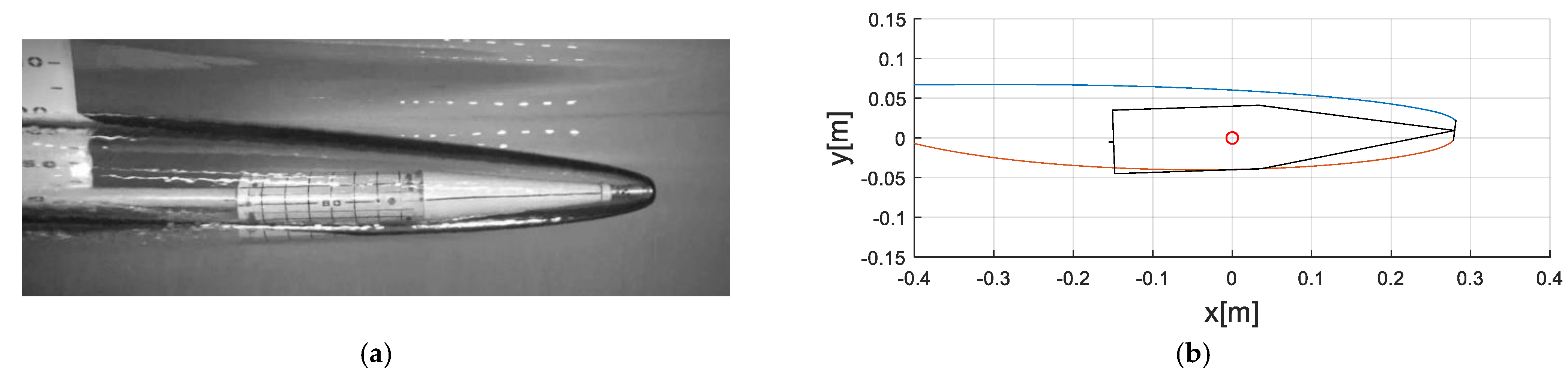
Figure 11 shows the straight level flight conditions with the predicted supercavity shape. The figure indicates that, except for a very small planing area of the vehicle transom, the supercavity created by the optimal cavitator tightly envelops the vehicle, resulting in minimum overall drag. It is noteworthy that the motion stability of the vehicle may be affected when the vehicle transom is considerably close to a cavity closure region featuring a highly unsteady flow behavior. If the designers want to ensure the torpedo operates inside the forward stable region of the supercavity, sufficiently away from the closure region, the minimum size of the supercavity can be imposed as a constraint in the design process.

5. Summary and Conclusions

A cavitator design method for straight-running-type supercavitating torpedoes was developed for practical application. It was used to determine the optimum cavitator for a specific torpedo configuration in terms of both the maximum range and basic motion stability of the torpedo. The design procedure was established as follows: (a) the cavitation number and cavitator type were determined by considering the stability of the ventilated supercavities and the operational concept of the torpedo; (b) the equations of force and moment equilibrium for straight level flight were iteratively solved to determine the straight level flight conditions; (c) the optimal cavitator that minimized the overall drag of the vehicle in straight level flight was finally chosen. In the proposed design method, the existing mathematical models were used to predict the supercavities created by disk- and cone-type cavitators and various hydrodynamic forces acting on the torpedo. The model experiments were performed on a small-scale supercavitating vehicle in a towing tank to confirm the validity of the mathematical models. The cavity shapes and the trim conditions predicted by the mathematical models show surprising agreements with the experimental results. The developed design method can also be useful for providing essential information such as the supercavity shape, overall drag, and straight level flight conditions required for the design of the control algorithms and propulsion systems of supercavitating torpedoes.
More precise CFD computations should be conducted to investigate the physics in further detail in the near future.

Author Contributions

Conceptualization, M.-J.K., K.-C.L. and M.-C.K.; methodology, M.-J.K., S.-H.K. and K.-C.L.; software, M.-J.K. and S.-H.K.; validation, B.-G.P. and M.-J.K. All authors have read and agreed to the published version of the manuscript.

Funding

This research was supported by grants from the National R&D Project “Study on the design of supercavitator and its performance” funded by the Defense Acquisition Program Administration of Korea, grant number 14-BR-EN-32.

Institutional Review Board Statement

Not applicable.

Informed Consent Statement

Not applicable.

Data Availability Statement

The data presented in this study are available on request from the corresponding author.

Acknowledgments

This work was supported by the National R&D Project grant (No. 14-BR-EN-32), which was funded by the Defense Acquisition Program Administration (DAPA), Republic of Korea.

Conflicts of Interest

The authors declare no conflict of interest.

References

  1. Rand, R.; Pratap, R.; Ramani, D.; Cipolla, J.; Kirschner, I.N. Impact Dynamics of a Supercavitating Underwater Projectile. In Proceedings of the ASME Design Engineering Technical Conferences, Sacramento, CA, USA, 14–17 September 1997. No. DETC97/VIB-39229. [Google Scholar]
  2. Ruggaber, W.; Hinding, W. Barracuda–guidance & control of a super cavitating high speed underwater missile. In Proceedings of the UDT Europe, Hamburg, Germany, 26–28 June 2006. [Google Scholar]
  3. Kirschner, I.N.; Fine, N.E.; Uhlman, J.S.; Kring, D.C.; Rosenthal, B.J.; Gieseke, T.A.; Kuklinski, R.; Varghese, A.N.; Stinebring, D.R.; Dzielski, J.E.; et al. Supercavitation Research and Development; Undersea Defense Technologies: Wakikiki, HI, USA, 2001. [Google Scholar]
  4. Ng, K.W. Overview of the ONR Supercavitating High-Speed Bodies Program. In Proceedings of the AIAA Guidance, Navigation, and Control Conference and Exhibit, Keystone, CO, USA, 21–24 August 2006. [Google Scholar] [CrossRef]
  5. Ahn, S. An Integrated Approach to the Design of Supercavitating Underwater Vehicles. Ph.D. Thesis, Georgia Institute of Technology, Atlanta, GA, USA, 2007. [Google Scholar]
  6. Semenenko, V.N. Some problems of supercavitating vehicle designing. In Proceedings of the International Conference on Superfast Marine Vehicles Moving Above, Under and in Water Surface (SuperFAST’2008), St. Petersburg, Russia, 2–4 July 2008. [Google Scholar]
  7. Savchenko, Y.N. Control of Supercavitation Flow and Stability of Supercavitating Motion of Bodies; RTO AVT Lecture Series on Supercavitating Flows Held at Von Karman Institute: Brussels, Belgium, 2002; p. 14. [Google Scholar]
  8. Choi, J.H.; Penmetsa, R.C.; Grandhi, R.V. Shape optimization of the cavitator for a supercavitating torpedo. Struct. Multidiscip. Optim. 2005, 29, 159–167. [Google Scholar] [CrossRef]
  9. Shafaghat, R.; Hosseinalipour, S.M.; Lashgari, I. Shape optimization of axisymmetric cavitators in supercavitating flows, using the NSGA II algorithm. Appl. Ocean. Res. 2011, 33, 193–198. [Google Scholar] [CrossRef]
  10. Alyanak, E.; Venkayya, V.; Grandhi, R.; Penmetsa, R. Variable Shape Cavitator Design for a Supercavitating Torpedo. In Proceedings of the 10th AIAA/ISSMO Multidisciplinary Analysis and Optimization Conference, Albany, NY, USA, 30 August–1 September 2004. [Google Scholar] [CrossRef]
  11. Alyanak, E.; Grandhi, R.; Penmetsa, R. Optimum design of a supercavitating torpedo considering overall size, shape, and structural configuration. Int. J. Solids Struct. 2006, 43, 642–657. [Google Scholar] [CrossRef] [Green Version]
  12. Semenenko, V.N. Artificial Supercavitation. In Physics and Calculation; RTO AVT Lecture Series on Supercavitating Flows Held at Von Karman Institute: Brussels, Belgium, 2001; p. 11. [Google Scholar]
  13. Paryshev, E.V. Theoretical Investigation of Stability and Pulsations of Axisymmetric Cavities. Tr. TsAGI 1978, 1907, 17–40. (In Russian) [Google Scholar]
  14. Kirschner, I.N.; Arzoumanian, S.H. Implementation and Extension of Paryshev’s Model of Cavity Dynamics. In Proceedings of the International Conference on Innovative Approaches to Further Increase Speed of Fast Marine Vehicles, Moving Above, Under and in Water Surface (SuperFAST’2008), St. Petersburg, Russia, 2–4 July, 2008. [Google Scholar]
  15. Mokhtarzadeh, H.; Balas, G.; Arndt, R. Effect of Cavitator on Supercavitating Vehicle Dynamics. IEEE J. Ocean. Eng. 2012, 37, 156–165. [Google Scholar] [CrossRef]
  16. Logvinovich, G.V. Hydrodynamics of Flows with Free Boundaries; Naukova Dumka Publ.: Kiev, Ukraine, 1969. (In Russian) [Google Scholar]
  17. Guzevsky, L.G. Approximation dependencies for axisymmetric cavities past cones. In Hydrodynamic Flows and Wave Processes; Institute of Thermal Physics Siberian Department of AS of USSR: Novosibirsk, Russia, 1983; pp. 82–91. (In Russian) [Google Scholar]
  18. Savchenko, Y.N.; Savchenko, G.Y. Estimation of efficiency of using supercavitation on axisymmetric hulls. Appl. Hydromech. 2004, 6, 79–83. (In Russian) [Google Scholar]
  19. Epshtein, L.A. Methods of Theory of Dimensionalities and Similarity in Problems of Ship Hydromechanics. Sudostroenie Publ.: Leningrad, Russia, 1970. (In Russian) [Google Scholar]
  20. Schlichting, H. Boundary Layer Theory, 4th ed.; McGraw-Hill: New York, NY, USA, 1960. [Google Scholar]
  21. Moroz, V. Development of the Concept of a Mathematical Model of Cavitations Flow Dynamics and its Experimental Verification; IHM NASU: Kyiv, Ukraine, 2018; p. 54. [Google Scholar]
  22. Paryshev, E.V. Mathematical modelling of unsteady cavity flows. In Proceedings of the Fifth International Symposium on Cavitation, Osaka, Japan, 1–4 November 2003; Available online: http://flow.me.es.osaka-u.ac.jp/cav2003/Papers/Cav03-OS-7-014.pdf (accessed on 29 April 2021).
  23. Tulin, M.P. Steady Two-Dimensional Cavity Flows about Slender Bodies; David Taylor Model Basin Report 834; Navy Dept. Publ.: Washington, DC, USA, 1953. [Google Scholar]
  24. Yegorov, I.T.; Sadovnikov, Y.M.; Isaev, I.I.; Basin, M.A. Artificial Cavitation; Sudostroyenie Publ.: Leningrad, Russia, 1971. (In Russian) [Google Scholar]
  25. ITTC-Recommended Procedures and Guidelines. Testing and Extrapolation Methods. High Speed Marine Vehicles Resistance Test. In Proceedings of the 25th ITTC, Fukuoka, Japan, 14–20 September 2008; Available online: https://ittc.info/media/1870/75-02-05-01.pdf (accessed on 29 April 2021).
Figure 1. Cavity pulsation phenomenon.
Applsci 11 06247 g001
Figure 2. Motion scheme for straight level flight.
Applsci 11 06247 g002
Figure 3. Free-body diagram of a supercavitating vehicle in a longitudinal vertical plane.
Applsci 11 06247 g003
Figure 4. Flowchart for determining the conditions of straight level flight.
Applsci 11 06247 g004
Figure 5. Flow diagram for the vehicle planing in the cavity.
Applsci 11 06247 g005
Figure 6. Schematic of the vertical fin.
Applsci 11 06247 g006
Figure 7. Small-scale supercavitating vehicle.
Applsci 11 06247 g007
Figure 8. Experimental and calculated cavity shapes at a fixed zero trim angle: (a) experiment; (b) calculation.
Applsci 11 06247 g008
Figure 9. Experimental and calculated trim conditions in a steady planing mode (disk-type cavitator. V = 9.12 m/s, σ = 0.064 ) : (a) experiment; (b) calculation.
Applsci 11 06247 g009
Figure 10. Experimental and calculated trim conditions in a steady planing mode (cone-type cavitator. V = 9.58 m/s, σ = 0.061 ): (a) experiment; (b) calculation.
Applsci 11 06247 g010
Figure 11. Straight level flight condition for the optimal cavitator ( d c = 0.04   m , δ c = 5.0 ° , α B = 0.222 ° ).
Applsci 11 06247 g011
Table 1. Comparison of the cavity dimensions obtained from the experiment and calculation.
Section No.Distances (mm)Diameter (mm),
Experiment
Diameter (mm),
Calculation
Deviation (%)
1506666.961.45
21008181.800.99
31509292.010.01
420010199.901.09
5250108105.871.97
6300112110.301.52
7350115113.401.39
8400117115.251.50
9450117115.890.95
10500116115.310.59
11550113113.570.50
Table 2. Information for the cavitator design.
DescriptionValue
Vehicle speed/depth140 knots/1.5 m
Vehicle overall length2.4 m
Vehicle diameter0.165 m
Vehicle conical part length0.69 m
Vehicle mass center from the cavitator1.532 m
Vehicle mass65.8 kg
Vertical fin span length0.1175 m
Vertical fin chord length0.02 m
Vertical fin wedge angle 6 °
Vertical fin root location from the cavitator2.274 m
Table 3. Upper and lower bounds and increments of each parameter for the iteration.
ParametersLower BoundUpper Bound Increment   ( Δ )
Diameter of the cavitator ( d c )0.037 m0.06 m0.001 m
Inclined angle of the cavitator ( δ c ) 0 ° 30 ° 0.001 °
Trim angle of the vehicle ( α B ) 0 ° 5 ° 0.001 °
Publisher’s Note: MDPI stays neutral with regard to jurisdictional claims in published maps and institutional affiliations.

