1. Introduction
Wheelchairs are widely used around the world to provide mobility to the elderly and disabled [
1]. However, the difficulty to access areas with curbs and stairs using a standard electric-powered wheelchair limits the scope of activities, thereby declining the quality of life of those who depend on electric-powered wheelchairs [
2]. Although slopes and elevators are being introduced to promote barrier-free locomotion, it is difficult to implement them in all public facilities. Therefore, climbing up and down the stairs is inevitably a critical issue with respect to user safety [
3]. With the increasing interest in the aging population and health welfare around the world, various studies on indoor electric wheelchairs for the elderly and disabled are being conducted [
4,
5,
6].
The recent developments in the field of electric wheelchairs can be categorized into the wheel-type and caterpillar type methods [
7]. The representative example of the wheel- type method is iBot. The iBot presents a method of climbing stairs by changing the angle of movement and the center of gravity of the occupant. The other type of method is the caterpillar, which is essentially, a track system. Tracks are often used in military vehicles such as heavy machinery, tanks, and armored vehicles. Because a caterpillar pushes the ground with a wide surface area, the contact pressure is low; therefore, driving in a rough terrain is convenient. However, each type of method has its respective drawbacks. In case of the iBot, owing to the statically unstable two-point grounding of the stairs, the user must hold the railing to maintain balance while climbing the stairs without the assistance of a caregiver [
2,
8]. The caterpillar is stable while climbing stairs; however, it is unsuitable for driving on level ground.
In this study, the authors attempt to develop a wheelchair that addresses the limitations of the use of only wheels or caterpillars in conventional electric wheelchairs by pro-moving flexibility in the use of wheels on level ground and caterpillars on stairs. Wheelchairs that drive both a caterpillar and a wheel at the same time have already been studied a lot, such as TGR Explorer, TopChair-S and Scewo bro. However, their slightly more complicated structure and higher price partially hinder a more extensive application among the elderly population and persons with disabilities [
9]. In the case of Scewo’s wheelchair, it is equipped with the iBot function, so it is expensive and very heavy at 101 kg. This study aims to reduce the weight and price with a simple structure, so that it can be applied to more disabled people and the elderly. The target weight of the wheelchair is 65 kg and the weight of the user who can ride it is 100 kg. In addition, it will be possible to provide more convenience by going up and down the stairs alone without the help of a guardian.
In this paper, we designed a transmission and pulley position conversion system to divide the wheelchair into two modes. Through mathematical calculations, the gear specifications of the transmission and the size of the pulley position conversion system are determined. The reliability of the transmission was verified through the stress analysis of the gear, and the drivability, stability, and operability of the wheelchair drive part were verified through the actual production.
2. Proposed Wheelchair Concept
Conventionally, electric wheelchairs comprising wheels and caterpillars are extremely heavy because the motors that drive the wheels and caterpillars are separate. In this study, the authors attempt to develop a lightweight electric wheelchair, incorporating both driving wheels and caterpillars in tandem, using a single motor.
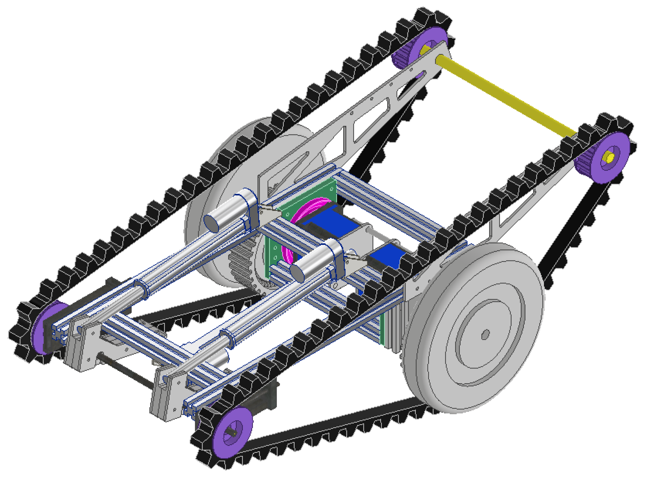
Figure 1 show a 3D model of an electric wheelchair. On flat ground, the wheelchair is driven by wheels and a landing gear located in front of the wheelchair, and while climbing stairs, it is driven by a caterpillar.
Basically, stairs are climbed by forming an entry angle using the landing gear, and when the front part of the caterpillar hits the first step of the staircase, the landing gear is folded and accordingly, a step of the staircase is climbed using the caterpillar. When one reaches the last step of the staircases, the landing gear is spread to prevent impact on the wheelchair. While descending the stairs, the first step is approached in a similar manner as that while ascending. After folding the landing gear and entering the staircase, the landing gear is spread again, before the center of gravity is completely crossed to prevent impact; thereafter, the landing gear is folded again and accordingly, the user descends the stairs. In the last step after having descended the stairs, the extended caterpillar at the rear of the caterpillar prevents impact.
3. Transmission System
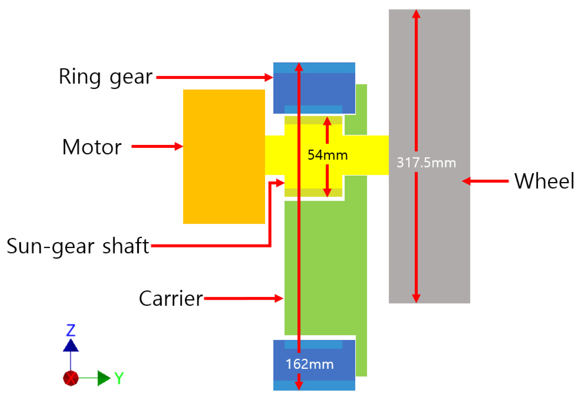
Figure 2 is a simplified schematic of the transmission. The transmission consists of a sun-gear shaft and ring gear. The motor is connected to the sun gear, and as the motor power transmits the power to the ring gear through the sun gear, it is decelerated by the number of teeth of the sun gear and ring gear. On the outer surface of the ring gear, a pulley is formed that drives the rubber track. Pulleys and wheels look like they consume a lot of power because they are in a state of constant rotation. However, when driving in one mode, the other mode does not consume much power because it is not loaded.
4. Specification
The specifications of the motor used for wheelchairs are shown in
Table 1. A geared motor equipped with a reducer is used to lower the speed of the wheelchair and allow for greater torque.
The maximum speed of an electric wheelchair, as recommended by the Ministry of Food and Drug Safety, must be 15 km/h or less [
10]. In this study, for the developed indoor electric wheelchair, a flat land speed of 5 km/h and a stair climbing speed of 1 km/h were ensured.
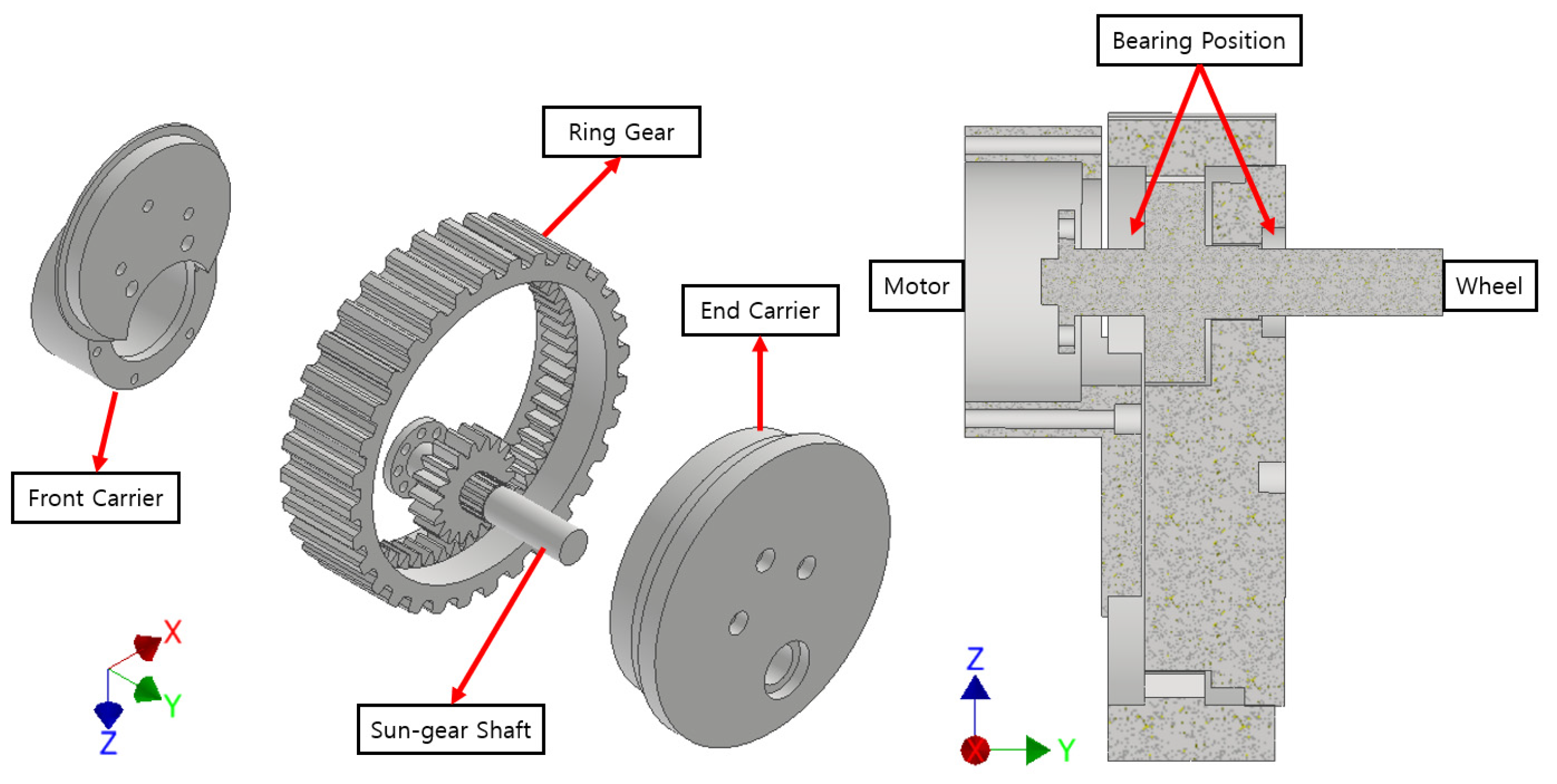
Figure 3 shows an exploded view and a cross-sectional view of the transmission. Since the gear specifications of the transmission is an important parameter in designing the pulley position conversion system, which is the core of this study, it will be dealt with in detail through mathematical calculations.
5. Pulley Position Conversion System
While driving the wheels and caterpillars in tandem, interference between the wheels and caterpillar can occur if the flat-ground driving mode and the stairs-climbing mode are not adequately distinguished. Such a situation can cause vibrations and the problem of directional distortion due to the speed difference between the two wheels, leading to major accidents while moving along staircases. Wheelchair accidents on staircases can be severe and even fatal [
1,
11]. To prevent this, the position of the driving pulley is changed to allow the wheelchair to be driven by both the caterpillars and wheels.
The following
Figure 4 presents an exploded view of the pulley position conversion system. By pushing the motor bracket using a linear actuator, the entire driving part is rotated to change the position of the pulley. The system is structurally capable of moving the pulley at angles of up to 90°. Furthermore, mathematical calculations were performed to clearly separate the wheel driving position and the stair climbing position within a limited displacement.
The linear actuator used in the pulley position conversion system is an electric linear actuator. Specifications are shown in
Table 2.
6. Mathematical Calculation
The degree of inclination of the electric wheelchair while driving on level ground should be such that the caterpillar is able to climbs the first unit of the staircase. Because a 650-mm caterpillar must be placed on a 20-cm staircase, it must be inclined to an angle greater than 18°. Therefore, the degree of inclination of the landing gear is set to 20°.
The slope of the extended caterpillar that is installed to prevent impact while descending stairs should be 35° based on the slope of the stairs with a height of 18 cm and a width of 26 cm, as per the stair installation standard. In the calculation, the value of the pulley radius is inclusive of the thickness of the rubber track. For moving on level ground, 317.5-mm wheels were used.
6.1. Running on Flat Ground
The motor shaft is the origin and the eccentric angle of the pulley with respect to the vertical axis is denoted by
θ (°). The clockwise direction is considered as positive. When a straight line inclined at 20°, contacts with the pulley and when the vertical distance between the motor shaft and the contact point is less than the wheel radius, it is possible to drive while the wheel is in contact. This is expressed by the following formula.
In inequality (1), to maximize the distance between the caterpillar and the wheel, the value of ecos (
θ + 20) must be minimum. Therefore, the value of cos (
θ + 20) is zero, and
θ is 70°.
6.2. Climbing Stairs
The calculation required to ascend/descend stairs is also centered around the motor shaft, as is the case for movement on flat ground. To ascend the stairs, the caterpillar that extends backward must be at the rear of the wheel. Therefore, the counterclockwise direction of the vertical axis of the origin is considered positive. While climbing stairs, only the caterpillar must touch the stairs; therefore, the distance from the origin to the bottom of the caterpillar must be greater than the radius of the wheel. Furthermore, because the wheel must not touch the ground even when the caterpillar is extended, a tangent line with a slope of 35° must be drawn such that the distance between the contact point with the pulley and the origin must be greater than the radius of the wheel. This is expressed as follows:
In inequality (4), to maximize the distance between the caterpillar and the wheel, the value of
ecosθ must be maximum; therefore, the value of
cosθ is 1, and consequently, the value of
θ becomes zero.
6.3. Gear Specification
Because the eccentricity and the center distance of the reducer gear have the same values, the determination of the gear specification is influenced. The module value of the reduction gear was set at three, and the ratio of the number of teeth between the inner and outer gears was set to 3:1. Because the difference between the number of teeth is three-fold, the pitch diameter of the inner gear and that of the outer gear also differ by three times. Accordingly, the relationship between the center distance and the outer gear pitch radius is as follows:
When the thickness of the belt is approximately 30 mm, the difference between the radius of the pulley including the belt, and the radius of the pitch circle of the ring gear should be 30 mm or more. In addition, if the height difference between the caterpillar and the wheel is small in a wheelchair being driven on a flat ground, a situation wherein the caterpillar touches even a small object, may arise. Therefore, it is necessary to determine the solution in which the difference between the wheel and the caterpillar is the maximum while flat driving on flat ground. In other words, it is necessary to determine the value at which the eccentricity becomes the maximum. This can be expressed as the following equation:
Inequality (2,6,7,9) are shown graphically in
Figure 5.
The optimized values are in the shaded area in
Figure 5. The number of teeth of the gear must be an integer, and therefore it is set to 54, which is the closest multiple of 3 to 55.52 mm. At this time, the radius of the pulley must be 113.5 mm or more, and the specifications of the transmission and the size of the pulley based on this are presented in
Table 3.
Using the above specifications, the flat land speed and the stair climbing speed of the wheelchair are 5.148 km/h and 1.242 km/h, respectively.
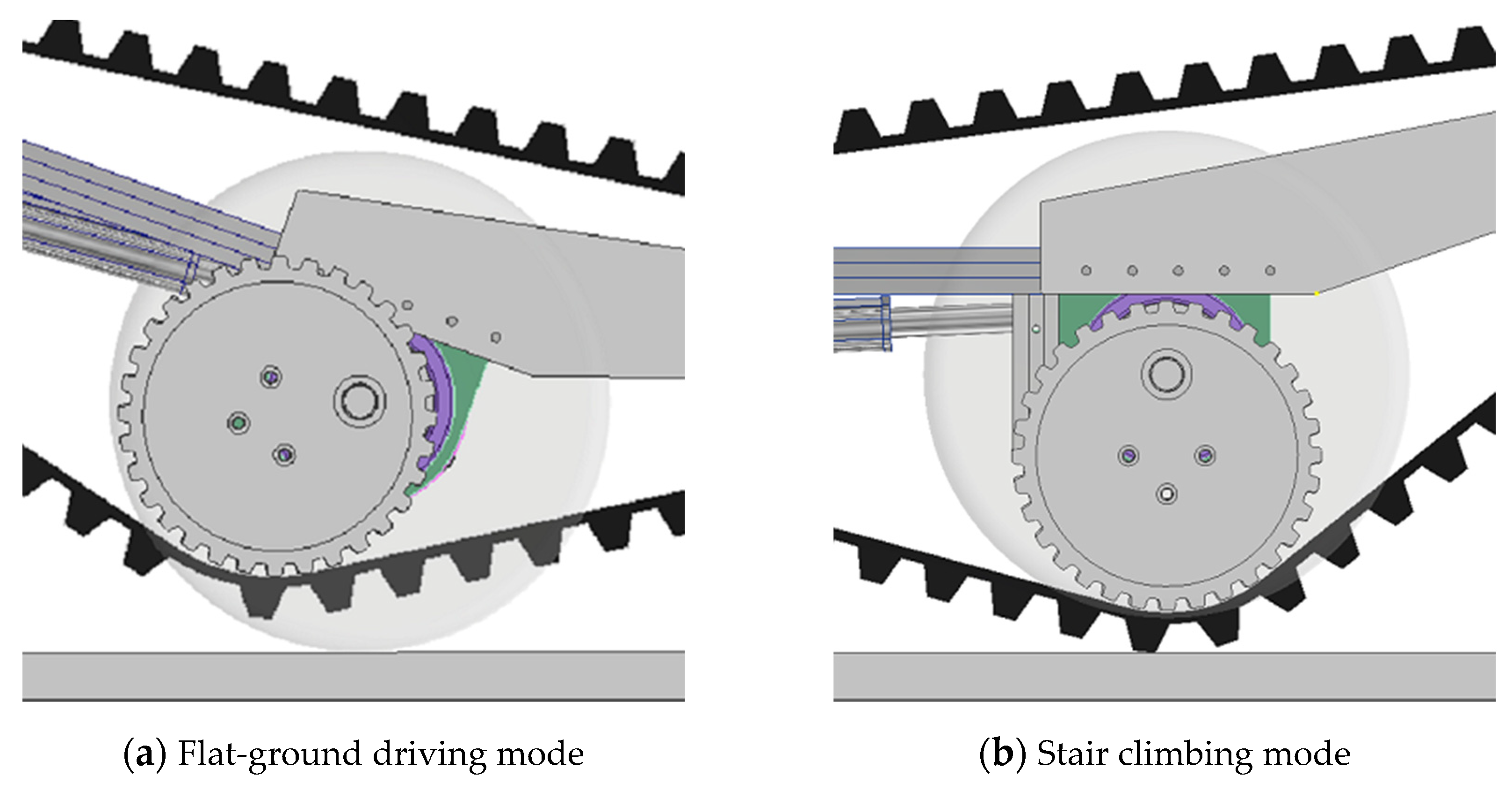
The following
Figure 6 shows the positions and sizes of the wheels and pulleys based on the above specifications.
6.4. Gear Reference Efficiency
The gear engagement efficiency was calculated based on the gear specification above. The gear contact ratio was calculated using Equation (10), and the gear reference efficiency was calculated using Equation (13) [
12].
Based on Equations (10) and (11), the contact rate is 1.97 and the reference efficiency is 0.994.
7. Gear Stress Analysis
Reliability is evaluated through stress analysis between the internal gear and the external gear of the reducer. Autodesk Inventor’s stress analysis program was used for the analysis. The material used for transmission was SCM420H, and the corresponding properties are shown in
Table 4 [
13].
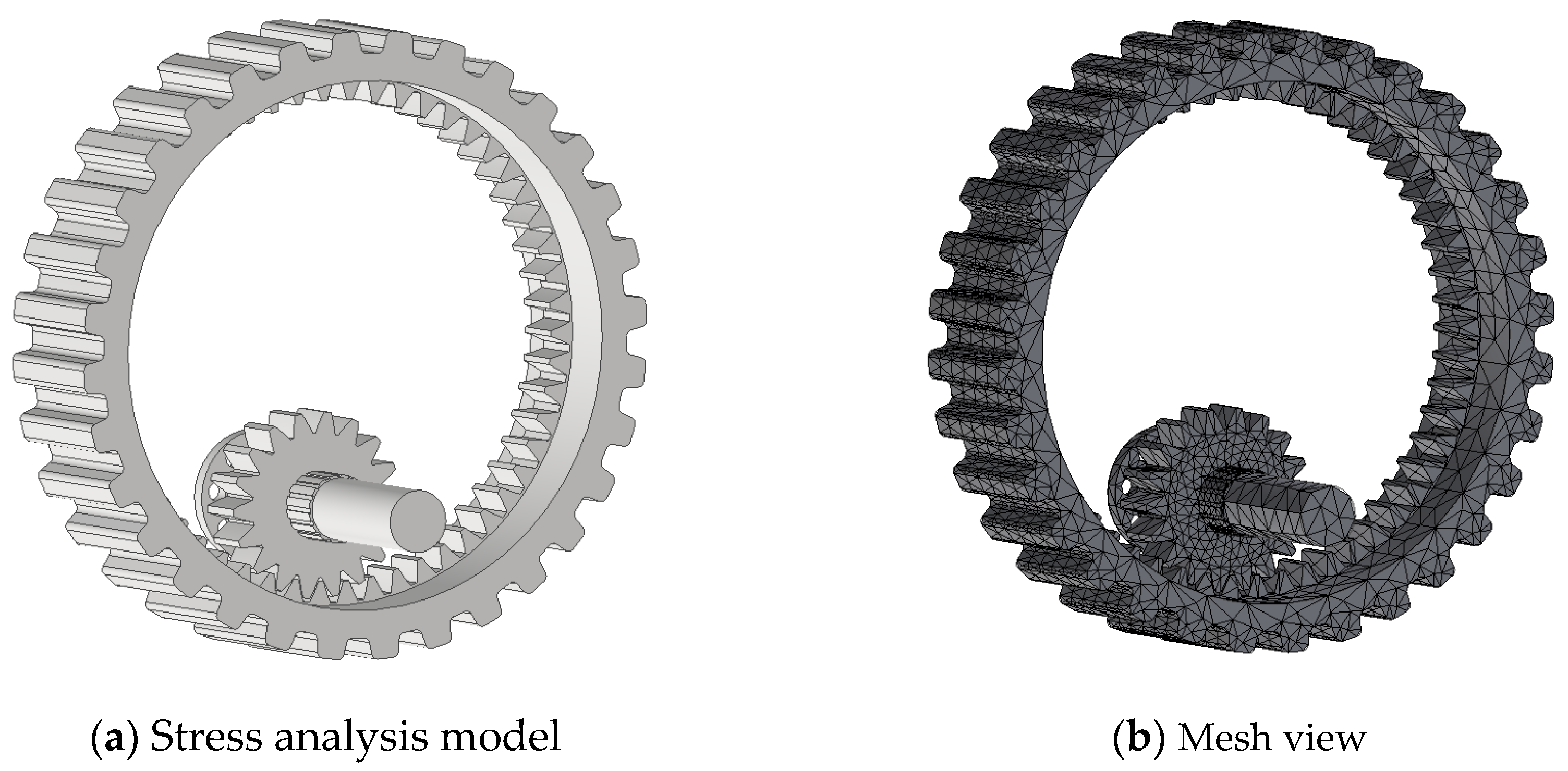
Figure 7a shows the geometry used in the analysis. The mesh consists of 63,029 nodes and 38,249 elements, as shown in
Figure 7b.
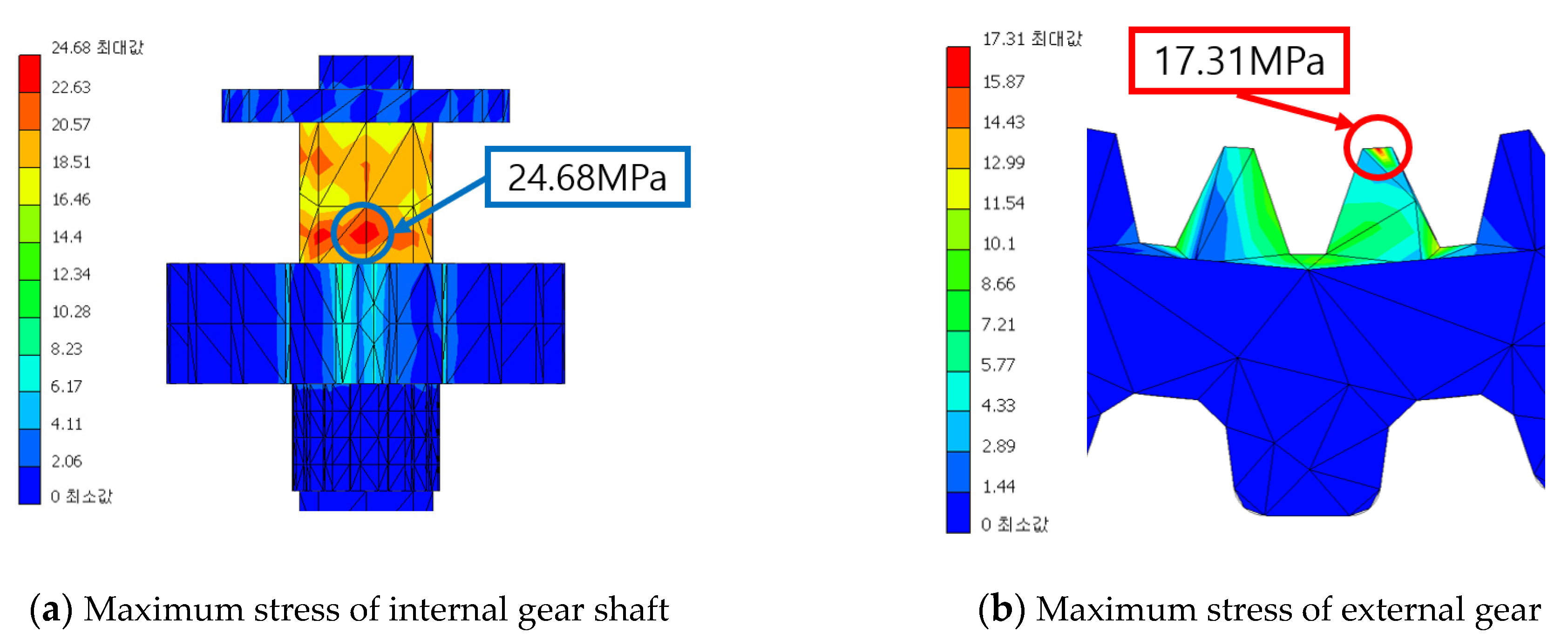
Figure 8 shows the constraints used in the analysis and the applied force. The sun gear shaft was pinned and a moment according to the motor specifications was applied to the sun gear shaft. The most extreme situation that can be applied to the gear by fixing the outside of the external gear is assumed.
The stress analysis results indicated that the maximum stresses applied to the internal and external gears were 24.45 MPa and 11.45 MPa, respectively. This stress analysis was performed by setting extreme conditions that may be applied to the driving part of the wheelchair. It was confirmed that fracture did not occur even under these extreme conditions, which, in turn, validated the stability of the main parts. The results of the stress analysis are shown in
Figure 9.
8. Manufacture
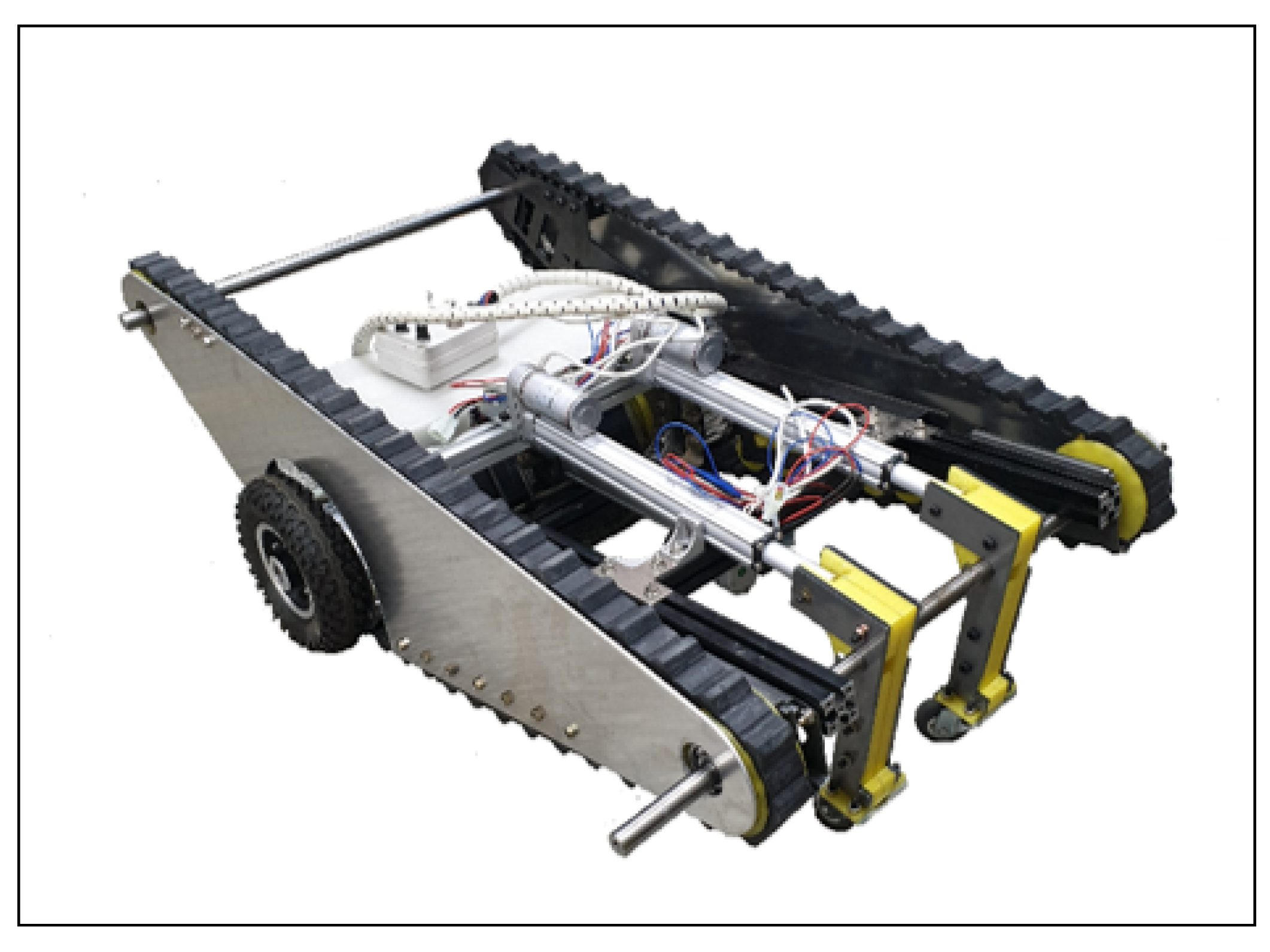
Figure 10 shows an actual manufactured wheelchair. The body was manufactured through aluminum profiles, and the parts were manufactured through laser processing, 3D printing, and cutting processing. The operability was confirmed by testing its ability to climb stairs and move on level ground.
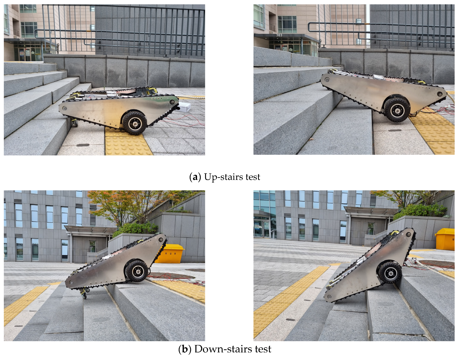
Stair climbing/descending test was conducted as shown in
Figure 11. Through this test, the operability of the landing gear and pulley position conversion system was con-firmed. In addition, the drivability and stability of the stairs were confirmed. The tested stairs were 15 cm high and 20 cm wide, and the weight of the wheelchair was 43 kg.
9. Conclusions
In this study, an electric wheelchair drive unit capable of climbing stairs and moving on level ground was developed based on a caterpillar and wheel in tandem. Through a 3:1 reducer, comprising a sun gear shaft and ring gear, the caterpillar and wheels were driven at different speeds simultaneously, allowing one to stably ascend/descend stairs. Because driving the caterpillar and wheel simultaneously could cause interference between them, a device that could changes the position of the pulley was incorporated to prevent interference, and the specifications, such as, the pulley angle, pulley radius, and system eccentricity, were calculated to determine the optimum value. The reference efficiency of the gear, was calculated to be 0.994, and the stability was confirmed through stress analysis. A lightweight electric wheelchair was developed in this study by removing the additional power required to drive the caterpillar and using a single motor to drive both the wheels and caterpillar.
However, this study has certain limitations, particularly in terms of the reliability of the wheelchair in climbing stairs. Unsafe situations arise because we devised a method ascend and descend stairs through only a mechanical mechanism without electronic control. We intend to address this limitation through additional research on climbing and descending stairs more safely through electronic control methods and structural completion. In addition, research on a wheelchair with a chair tilting system through electronic control is also necessary. Since there may be a risk due to a change in the center of gravity when ascending and descending stairs, we aim to devise a chair system that is suitable for this drive system through further research.
This study developed a wheelchair drive unit capable of climbing stairs to provide a barrier-free life to the elderly and the disabled. It is expected that this study can provide a more pleasant environment to the disabled. Furthermore, the proposed driving unit presents the possibility of creating more efficient driving units not only for wheelchairs, but also for vehicles that are driven on both rough and flat terrain such as military vehicles, heavy equipment, and unmanned robots.
Author Contributions
Data curation, J.H.; Formal analysis, T.K.; Investigation, W.J.; Software, J.L.; Writing—original draft, J.L.; Writing—review & editing, S.O. All authors have read and agreed to the published version of the manuscript.
Funding
This research was supported by the Chung-Ang University Graduate Research Scholarship in 2020.
Institutional Review Board Statement
Not applicable.
Informed Consent Statement
Not applicable.
Data Availability Statement
Not applicable.
Acknowledgments
This work was supported by the Technology Innovation Program (10084565, Development of smart wheelchair power assist module for outdoor activity and off-road drive of the disabled) funded By the Ministry of Trade, Industry & Energy (MOTIE, Korea).
Conflicts of Interest
The author declares no conflict of interest.
References
- Ikeda, H.; Toyama, T.; Maki, D.; Sato, K.; Nakano, E. Cooperative step-climbing strategy using an autonomous wheelchair and a robot. Robot. Auton. Syst. 2020, 135, 103670. [Google Scholar] [CrossRef]
- Onozuka, Y.; Tomokuni, N.; Murata, G.; Shino, M. Dynamic Stability Control of Inverted-Pendulum-Type Robotic Wheelchair for Going Up and Down Stairs. In Proceedings of the 2020 IEEE/RSJ International Conference on Intelligent Robots and Systems (IROS), Las Vegas, NV, USA, 24 October–24 January 2021; pp. 4114–4119. [Google Scholar]
- Sasaki, K.; Eguchi, Y.; Suzuki, K. Stair-climbing wheelchair with lever propulsion control of rotary legs. Adv. Robot. 2021, 34, 802–813. [Google Scholar] [CrossRef]
- Xing, C.; Lee, H.C.; Cho, K.S. The research of disapproval in silver products-testified via electric wheelchair. Sci. Emot. Sensib. 2010, 13, 317–326. [Google Scholar]
- Kim, Y.-P.; Ham, H.-J.; Hong, S.-H.; Ko, S.-C. Design and Manufacture of Improved Obstacle-Overcoming type Indoor Moving and Lifting Electric Wheelchair. J. Korea Acad. Ind. Coop. Soc. 2020, 21, 851–860. [Google Scholar]
- Song, W.K. Prospects of rehabilitation welfare devices: Based on assistive and robotic devices. J. Rehabil. Welf. Eng. Assist. Technol. 2015, 9, 1–9. [Google Scholar]
- Cho, W.; Cho, H.; Kim, J.; Kim, S.; Moon, M. Design of tracked mechanism for stair climbing wheelchair. In Proceedings of the Korean Society of Precision Engineering Conference, Seoul, Korea, 1 June 2011. [Google Scholar]
- Uustal, H.; Minkel, J.L. Study of the Independence IBOT 3000 Mobility System: An innovative power mobility device, during use in community environments. Arch. Phys. Med. Rehabil. 2004, 85, 2002–2010. [Google Scholar] [CrossRef] [PubMed]
- Tao, W.; Xu, J.; Liu, T. Electric-powered wheelchair with stair-climbing ability. Int. J. Adv. Robot. Syst. 2017, 14, 1729881417721436. [Google Scholar] [CrossRef]
- KS P ISO7176-6. Wheelchairs—Part 6: Determination of Maximum Speed of Electric Wheelchairs; ISO/TC 173/SC 1,2. Available online: https://sites.lafayette.edu/wheelchair-team/files/2020/09/Wheelchair_Hill_Assist_Conceptual_Design_Report.pdf (accessed on 3 April 2021).
- Calder, C.J.; Kirby, R.L. Fatal wheelchair-related accidents in the United States. Am. J. Phys. Med. Rehabil. 1990, 69, 184–190. [Google Scholar] [CrossRef] [PubMed]
- KHK Stock Gears. GEAR TECHNICAL REFERENCE. Gear Knowledge. Available online: http://khkgears.net/gear-konwledge/gear-technical-reference/ (accessed on 3 April 2021).
- ‘Longhai’ Steels. Available online: https://www.steelss.com/Carbon-steel/scm420h.html (accessed on 5 April 2021).
| Publisher’s Note: MDPI stays neutral with regard to jurisdictional claims in published maps and institutional affiliations. |
© 2021 by the authors. Licensee MDPI, Basel, Switzerland. This article is an open access article distributed under the terms and conditions of the Creative Commons Attribution (CC BY) license (https://creativecommons.org/licenses/by/4.0/).


