1. Introduction
Sound scattering has received significant attention from researchers all over the world, and the research related to sound scattering in the free field has matured remarkably. The acoustic scattering of targets in shallow water is currently the main research orientation of scholars from around the world. The research on targets’ scattering characteristics in shallow water has gradually matured, and the research methods on the scattering characteristics of the shallow-water target are becoming increasingly abundant.
In 1953, Morse [
1] proposed the theoretical basis of Kirchhoff approximation. On the basis of the Rayleigh series, the main methods of scattering research are the Watson–Sommerfeld transformation method [
2], resonance scattering theory [
3], and the singularity expansion method [
4]. These methods can investigate the scattering mechanism and echo components in both time and frequency domains. However, the rigorous theoretical solutions that have been proposed are only applicable to some simple goals. Various numerical and approximate solutions have emerged for the calculation of the acoustic scattering field of complex targets, and the main methods include the finite element method (FEM) [
5], the boundary element method [
6], the T matrix method [
7], the finite difference time domain (FDTD) method [
8], the wave superposition method [
9], and thin shell theory.
For the scattering problem with certain boundary conditions, Ingenito [
10] first proposed a single scattering model to solve the problem of acoustic scattering in channels by using the waveguide acoustic method. However, the calculation of the acoustic scattering field in this method is limited to spherical targets and it is unsuitable for complex targets. Makris [
11] proposed the spectral superposition method based on the work of Ingenito, who decomposed the waveguide Green’s function into the plane wave spectrum, including the discrete and continuous spectra, which is, both normal and side waves. Huang and Gaunaurd [
12] studied the analytical solution for the acoustic scattering field that is caused by a spherical target near a single interface using the image method.
In recent years, scholars from various countries have proposed some methods for solving both sound scattering and radiation to obtain accurate results efficiently with a small amount of calculation. Sara R. Martin [
13] combined the edge source integral equation with the BEM to deal with the problem of sound scattering in the free field, which greatly reduced the number of calculations. Liu Qinghuo [
14] combined the difference time-domain method with far–near field transfer theory to deal with the problem of elastic wave scattering of three-dimensional targets. Shang Dejiang [
15] combined the FEM with normal modes to study the acoustic field of complex targets in a channel, effectively predicting the acoustic scattering field. Irena Lucifredi [
16], considering the reflections between the target and the seabed, proposed a hybrid method to calculate the scattering problem of the buried elastic shell target combining the virtual source method and spectral integration to deal with the scattered sound field in the layered medium. Sven M. Ivansson [
17] calculated the scattered sound field of a series of cylinders. Tengjiao He [
18] applied the equivalent element method to calculate the sound field scattered by the target in the axisymmetric shallow sea waveguide. Derek R. Olson [
19] studied the ocean bottom scattering sound field in multi-layered media. Alexander B. Baynes and Oleg A. Godin [
20] used the radiation of a virtual source instead of the target sound scattering to solve the target scattering sound field in the shallow ocean waveguide, but this method can only calculate the low-frequency shallow target.
When considering the deep-sea conditions, the influence of the sea surface on the elastic target’s impedance decreases when the elastic target is far from the sea surface. In this study, through the acoustic scattering simulation in the free field, the acoustic scattering field is equated to the radiation field of a directional point source; then, the directional point source is placed in the marine environment using ray acoustic to calculate the distribution of the scattering field. This method considers the multiple complex coupling effects between the elastic structure and marine environment. Accurate and reliable calculation results can be obtained when the elastic structure is far from the ocean boundary; this method only performs finite element coupling calculations under free field conditions, greatly reducing the amount of mesh and significantly improving the calculation efficiency as compared with performing finite element calculation in the entire channel. This method combines short-range finite element calculation with the acoustic ray calculation in the long range and it can realize the rapid calculation of the large-scale acoustic scattering field in the complex marine environment.
2. Theory
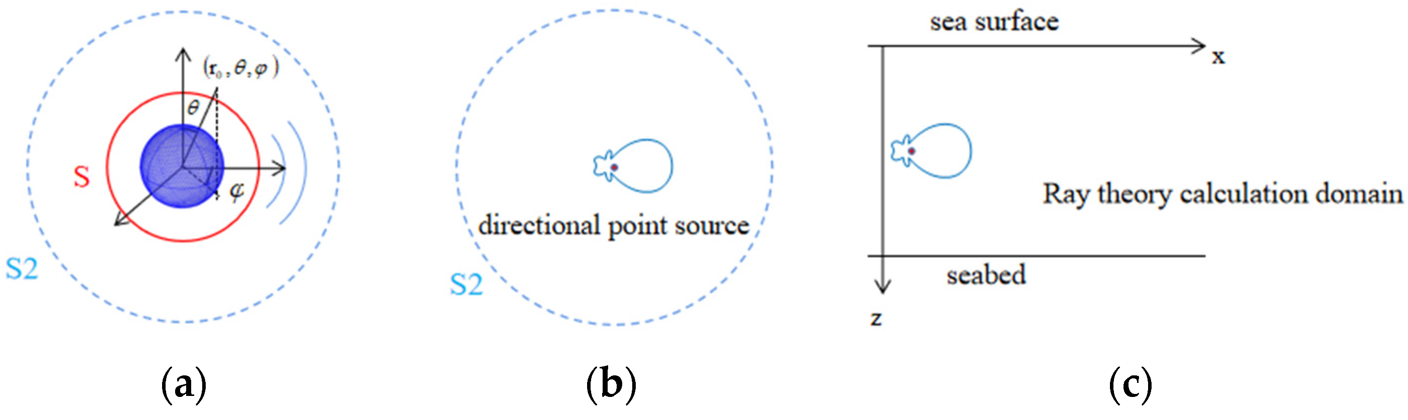
Figure 1 shows the schematic diagram of the equivalent method of the directional point source. In the deep-sea environment, the target is far from the sound field boundary. Thus, the boundary has little effect on the surface impedance characteristics of the scattering target. The reaction of the boundary to the scattering target is ignored. The initial scattering field of the elastic target is calculated under the free field condition, which is, the multi-physics coupling finite element model of the sound scattering of the scattering target in the free field is established to calculate the scattering sound field S presented in
Figure 1a. Subsequently, using finite element calculation to obtain the near-field scattering field sound pressure surrounding the scattering target, the scattering field is expanded by spherical waves to calculate the scattering sound pressure of any far field S2 shown in
Figure 1a and obtain the sound pressure spatial directivity of the scattering field. The complex scattering field of an elastic target is equivalent to the radiation field of a directional point sound source that has different source intensities in different directions and propagates as a point source spherical wave in any determined direction, as shown in
Figure 1b. Given the attenuation law of the spherical wave propagation of the radiation field of any structure that approaches a point sound source in a sufficiently far field, the equivalence has an equivalent rationality in the sound far field. Subsequently, the directional sound source is placed in the ocean channel environment, and ray theory is used to calculate the sound scattering pressure distribution of the far field in the ocean channel, as shown in
Figure 1c.
2.1. Theory of Directional Point Source Equivalence
The elastic structure is placed in the free field, and the finite element multi-physics coupling method is used to calculate the near-field sound scattering field, as shown in
Figure 1a.
The coupling equation for finite element calculation can be expressed as:
where
is an imaginary unit;
is the angular frequency;
Ks,
Cs, and
Ms represent the stiffness, damping, and mass matrices of the unconstrained part of the structural grid, respectively;
Ka,
Ca, and
Ma represent the stiffness, damping, and mass matrices of the unconstrained part of the fluid grid, respectively;
Kc represents the coupling stiffness matrix;
Fat is the acoustic excitation under the acoustic system;
Fst is the excitation on the structures; and, there is no incentive on the structure of this article, so
Fat is 0. If the sound pressure of discrete points on the spherical surface (S) of the surrounding structure is
, then it is the linear superposition of the incident and scattered sound fields. When no elastic structure exists, the same finite element calculation can be used to obtain the incident sound pressure of discrete point S on the spherical surface as
. Subsequently, the sound scattering pressure on spherical surface S is
.
According to the sound scattering pressure
of spherical surface S, the sound field on the spherical surface can be expanded by spherical waves to calculate the sound pressure S2 of the far field. The sound scattering field in the free field satisfies the spherical coordinate system’s Helmholtz equation. The formal expression of the scattered sound pressure can be obtained as (omit time factor
ejωt)
where
is the Legendre function,
is the Hankel function of the second kind, and
is the coefficient.
The orthogonality of the Legendre function is applied to solve formula (2).
Using the orthogonality of the Legendre function, when
, the integral result is 0. When
, the left side of Equation (3) is equal to
.
In order to better transform formula (4), let the function of
and
be equal to
.
where the orthogonality of the Legendre function can be expressed as
Both sides of Equation (5) are multiplied by and , and the points of .
The value of
can be obtained through the above calculation process.
where the orthogonality of the trigonometric function is expressed as
By substituting coefficients and into Equation (2), the function expression of sound scattering pressure and the sound scattering pressure of any field point can be calculated.
The sound pressure field of a directional point source can be expressed as
, as shown in
Figure 1b. In far field
, let
to obtain
. That is, the sound scattering field of the elastic structure is equivalent to that of a directional point source.
2.2. Ray Theory
In this study, ray theory is used to calculate the sound field distribution of directional point sound sources in the ocean channel. The ray theory calculates the target sound field in the waveguide, as shown in
Figure 1c. The sound pressure of the sound field can be expressed in the following form [
21]:
where
A is the sound pressure amplitude, which is, the sound pressure amplitude of the directional point source obtained in
Section 2.1; the wave number is expressed as
, where
is the speed of sound at the reference point and
is the refractive index;
is the phase; and,
is the eikonal, which is the length dimension that indicates the change of phase. By substituting this form of solution into the wave equation, the following relational expression can be obtained:
From the eikonal equation and Snell’s law, we can obtain . According to Gauss’ theorem, the sound ray trajectory equation, and Snell’s law, and while ignoring the constant factor, the sound pressure amplitude is reflected as the root value of the sound intensity. The trajectory of the sound rays that are emitted at any angle from the sound source in the seawater channel can be solved.
3. Numerical Simulation Analysis
This section focuses on the factors that may affect the accuracy of the solution during the application of the directional point source equivalent method: the selection of the equivalent position of the directional point source and the influence of the deep-sea waveguide interface on the scattered sound field. The accuracy of the method in different situations is obtained.
3.1. Applicable Conditions for Directional Point Sources Equivalence
This paper proposes the prediction method for deep-sea target sound scattering based on the equivalence of the directional point sound source. The complex elastic scattering field is equivalent to the radiation field of a directional point sound source, and the equivalent is only held in the far field. In the near-field area, it can be regarded as the interference superposition of incoming waves at different positions of the structure, according to the Helmholtz integral formula. The sound field does not only have radial radiation components but also lateral non-radiation components. Only at a distance far enough, the lateral non-radiation components account for enough small, it can be considered that the far-field condition is satisfied, and the far-field scattered field of the elastic structure is approximately equivalent to the radiation field of a directional point sound source. The following is a simulation analysis of the applicability of this equivalence.
The FEM is used to analyse the sound scattering field of an elastic spherical shell in the free field. The spherical shell has a radius of 10 m, a thickness of 0.1 m, and a plane wave with a frequency of 50 Hz incident on the elastic spherical shell horizontally. The density of the spherical shell is
ρs = 7850 kg/m
3, the Young’s modulus is
Es = 2 × 10
11 Pa, and the Poisson’s ratio is
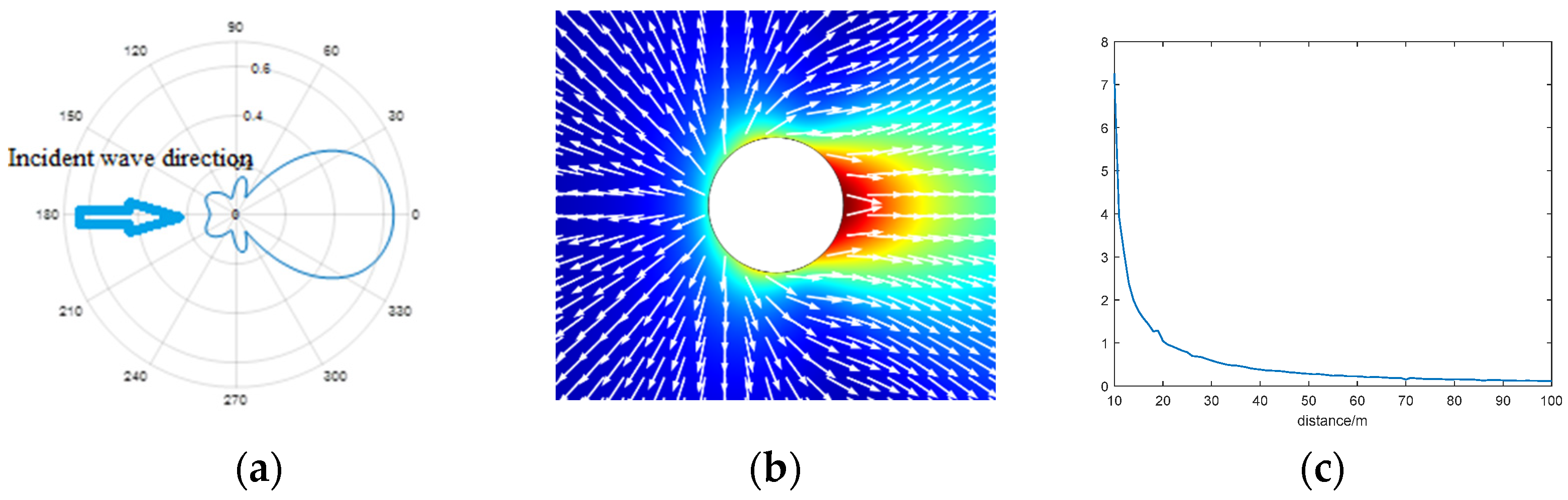
μs = 0.33. The far-field sounds of the sound scattering field pressure directivity diagram (
Figure 2a) and the near-field acoustic energy flow vector diagram (
Figure 2b) are drawn, which indicate the significant spatial directional difference of the scattering field. The scattering main lobe is formed in the 0° direction, whilst multiple scattering side lobes exist in other directions. The near-field acoustic energy flow vector diagram of the scattering field presented in
Figure 2b shows that, in the near field, the acoustic energy flowing in different directions do not flow out from the same sound centre. Transverse acoustic energy flow components exist. The proportion of transverse acoustic energy flow components decreases with the increase of the propagation distance, and the acoustic energy flow in different directions tends to flow out from the same sound centre. Additionally, the colour indicates the level of sound pressure, the red area has a higher sound pressure, and the blue area has a lower sound pressure.
Figure 2c shows the transverse acoustic energy flow and the radial sound in the 0° direction from near and far. The ratio of energy flow further illustrates this point.
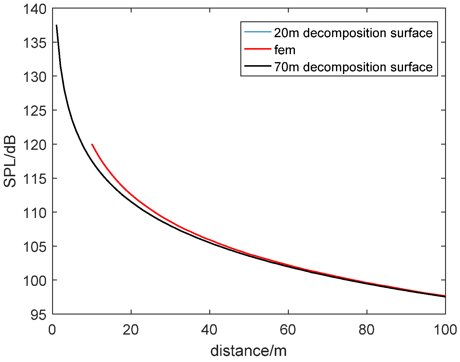
The sound pressures of the discrete points on the spherical surface are extracted at the outer radii of 20 and 70 m, the spherical wave is orthogonally decomposed, and the sound pressure of the scattering field from near and far is calculated, according to the finite element simulation.
Figure 3 shows the comparison of the scattering sound pressure calculated based on the spherical wave decomposition of the sound pressure at different positions in the 0° direction with the finite element direct calculation result. The scattering field calculation result is consistent with the finite element direct calculation result at a position that is greater than the distance from the decomposition surface. The results indicate that accurate and reliable far field scattering fields can be obtained based on the spherical sound pressure at different positions, providing convenience for the finite element simulation calculation, which is, the spherical sound pressure interface can be selected close to the spherical shell to reduce the amount of finite element sound field grids and improve the calculation efficiency.
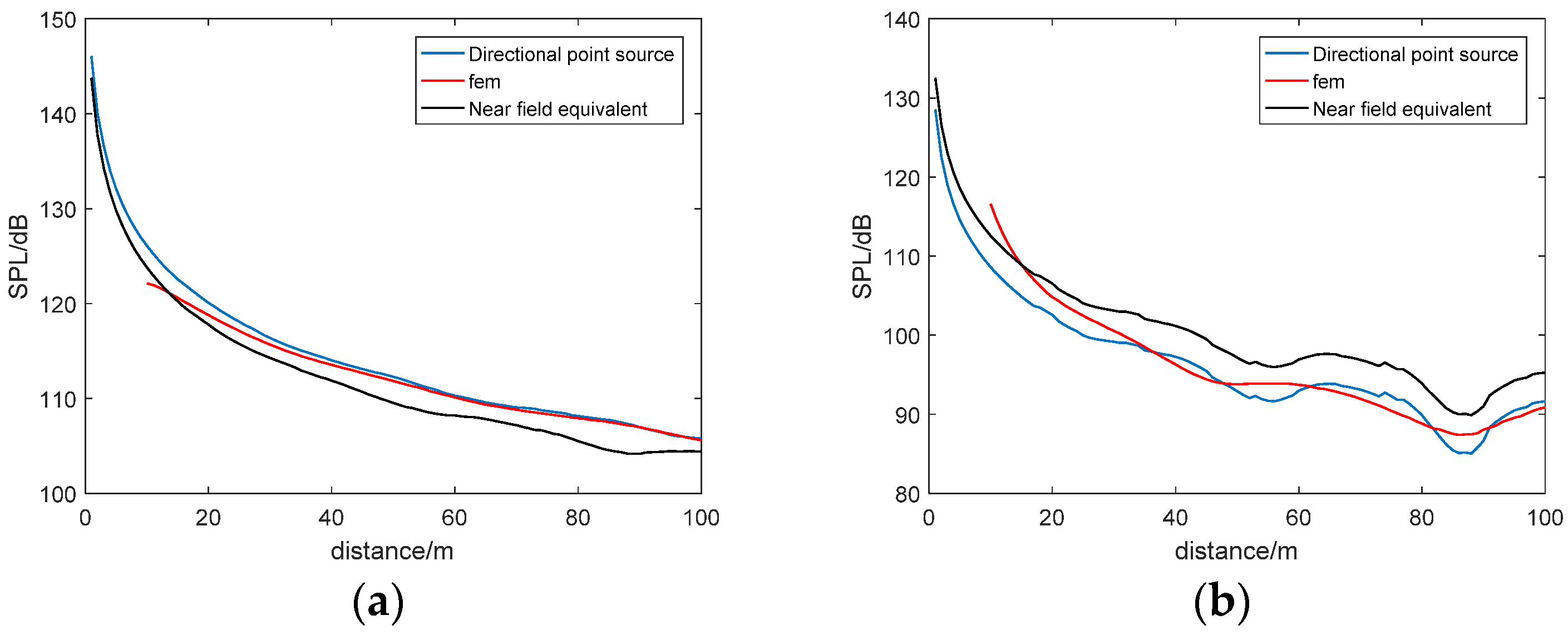
Subsequently, the spherical surface at 20 m is selected, and the discrete sound pressure on the spherical surface is calculated. The 20 m in the approach and the 10,000 m in the far field are equivalent to the directional point sound source. The directional point sound source is placed at the 400-m deep ideal ocean channel half-depth position, the sea surface is an absolute soft boundary, the seabed is an absolute hard boundary, the sound velocity in water is c = 1500 m/s, and density is ρ = 1000 kg/m
3. The sound scattering field in the deep-sea environment is calculated.
Figure 4 shows the sound pressure from near to far in the 0° direction and 80° direction. The comparison of the sound pressure distribution with the finite element direct calculation results shows that the sound pressure that is calculated based on the far-field sound pressure for the directional point source equivalent calculation is consistent with the finite element direct calculation results, whilst the near-field sound pressure calculation results lead to a large calculation error, indicating that an equivalent position that is far enough must be selected for the equivalence of the directional point sound source.
3.2. Influence of Interface on the Calculation Accuracy of Scattering Field in Marine Environment
In the directional point source method, the deep-sea channel interface is considered far from the target, and the interface slightly affects the sound scattering field near the target. Therefore, the sound scattering field near the target should be replaced by the sound scattering field of the free field. The influence of the interface on the sound scattering field is ignored. In actual problems, the interface has an impact on the scattering of the target. Therefore, this section considers establishing the deep-sea acoustic channel model under the 50 Hz condition. The target is a spherical shell with a radius of 10 m and a thickness of 0.1 m, the density of the spherical shell is ρs = 7850 kg/m3, the Young’s modulus is Es = 2 × 10¹¹ Pa, the Poisson’s ratio is μs = 0.33, and the sea surface is an absolute soft boundary. The seabed is an absolute hard boundary, the sound velocity in water is c = 1500 m/s, and density is ρ = 1000 kg/m3.
The incident wave is along the positive × direction with a frequency of 50 Hz, as seen in
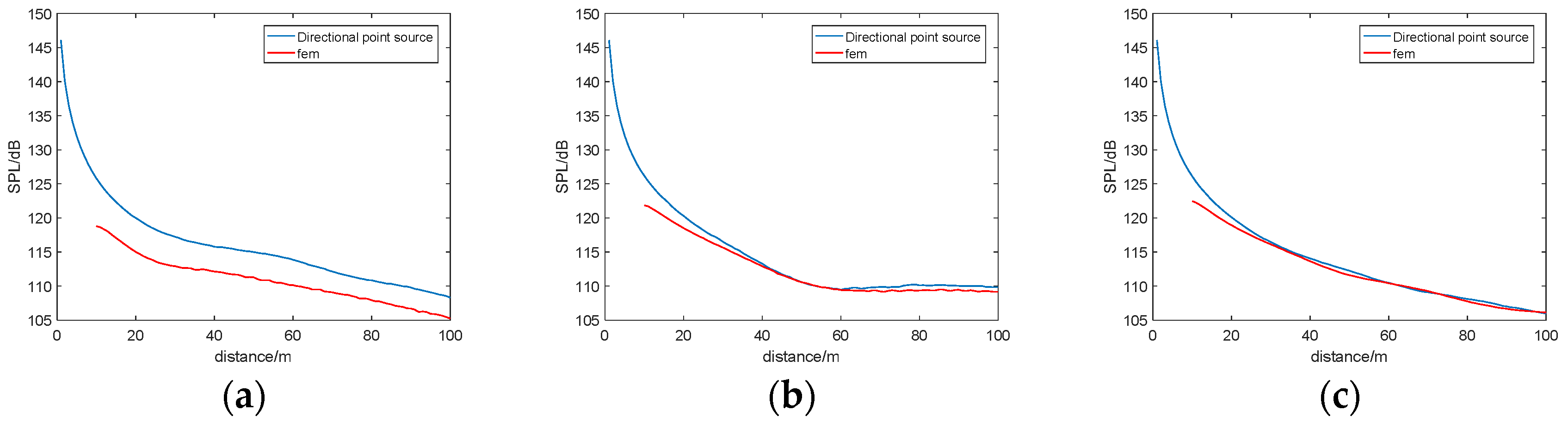
Figure 1, and the distance from the target to the lower boundary is 270 m. The sound scattering field with the distance from the target to the upper interface of 20, 30, and 180 m is calculated and compared with the finite element model.
For
Figure 5b,c, although the two curves fit well, a deviation remains. Secondary scattering causes the deviation. When the target is equivalent to the directional point source, the existence of the interface is ignored, and the interface does not cause secondary scattering. In the actual channel, multiple scattering of scattered waves back to the target occurs after passing through the interface. The closer the target is to the interface, the greater the secondary scattering and the poorer the accuracy of the directivity point source.
Figure 6 shows that, when the target is 20 m away from the interface, a big deviation exists between the results of the directivity point source method and the FEM. The calculation results reach a relatively stable state at 30 m from the interface. The two curves are in good agreement when the target is 180 m away from the interface, indicating that, when close to the sea surface, ignoring the influence of the surface impedance of the elastic structure on the sea surface may bring certain errors.
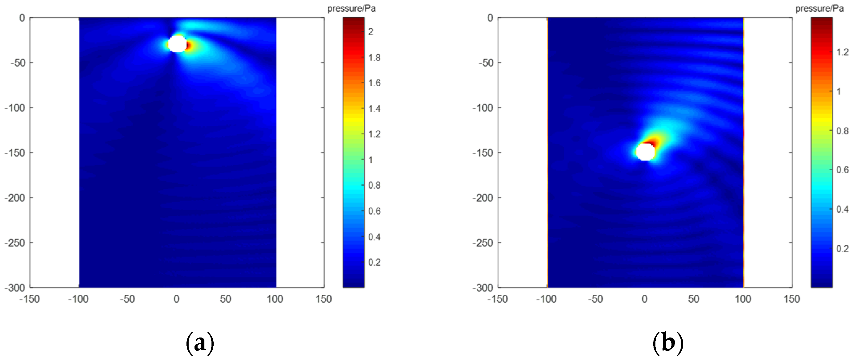
Figure 7 presents a diagram of the sound scattering field of a spherical shell located at different positions of the channel when a plane wave is obliquely incident upwards. The scattered sound field between the target and the upper interface shown in
Figure 7a is very large, reaching 1 Pa, indicating that the ratio of the secondary scattering accounting for the sound scattering field is large and the sound scattering field between the target and the interface shown in
Figure 7b is very small, further indicating that, when the target is far from the interface, the multiple scattering between the target and the interface accounts for a small proportion of the scattered sound field.
Figure 6 clearly shows that, when the target is very close to the interface, the calculation results of the target sound scattering field that are calculated by the directional point source method and the FEM are very different as the distance between the target and the boundary increases. The calculation result of the directional point source is near the finite element calculation result, which indicates that, when the distance to the sea surface is short, ignoring the influence of the surface impedance of the elastic structure on the sea surface may bring certain errors. Under the channel conditions in this section, when the target distance from the interface reaches the wavelength, the interface has little effect on the equivalent method of the directional point source.
3.3. Sound Scattering Field of Elastic Structure in a Typical Deep-Sea Channel
The submarine model that is selected in this section is the internationally published standard submarine model, i.e., the benchmark submarine target model [
22]. The length of the submarine is 61.5 m, the diameter of the hull is 7.5 m, the height of the podium is 3.5 m, and the thickness of the hull is 0.03 m.
A 5000-m deep ideal waveguide is established when considering the target scattering sound field of the submarine in the deep-sea waveguide. The upper boundary of the waveguide is an absolute soft boundary, and the lower boundary is an elastic boundary. The longitudinal wave velocity is 3800 m/s, the transverse wave velocity is 1800 m/s, the density is 1800 kg/m
3, and the attenuation coefficient 0.5.
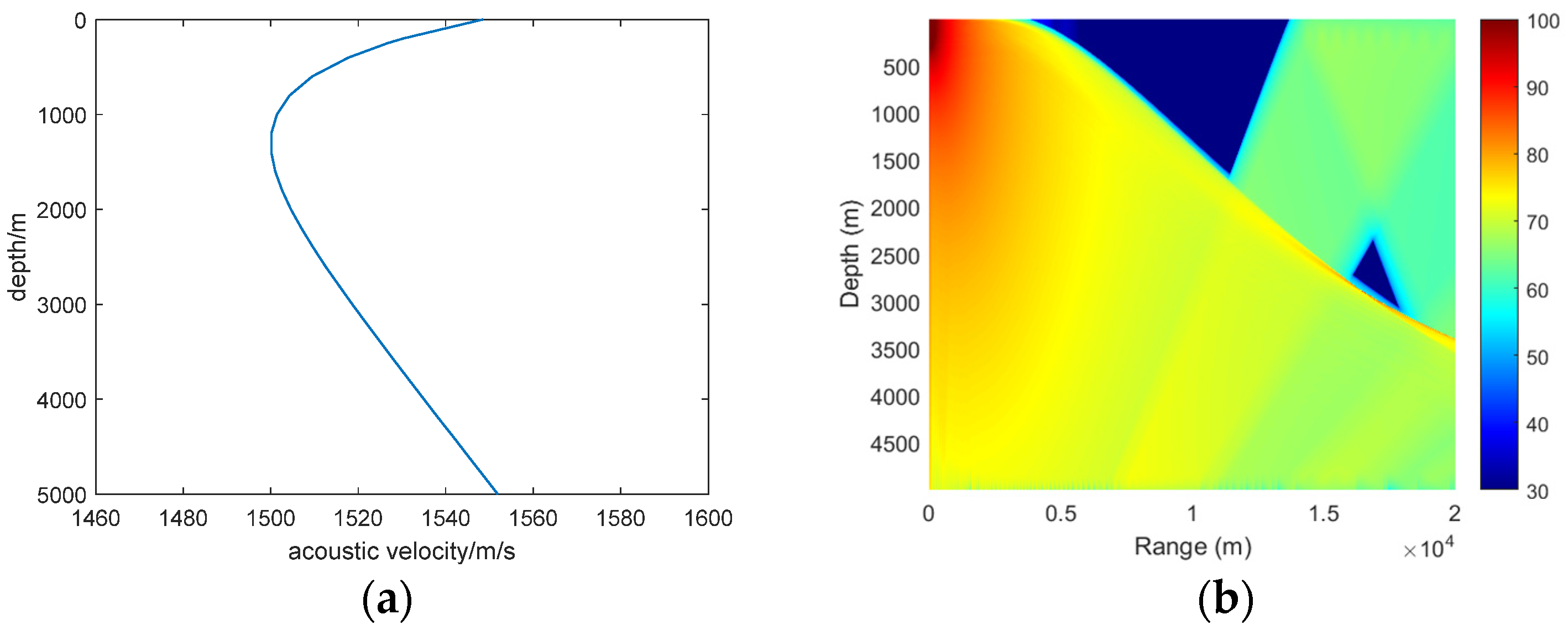
Figure 7a shows the sound velocity profile of the deep-sea waveguide, which is from South China Sea; the density of water is ρ = 1000 kg/m
3 and the submarine dives at a depth of 150 m. The sound field is incident from the bow direction, and the side scattered sound field is drawn.
Figure 7b shows the calculation result.
Figure 7b is the sound scattering field of the submarine model in the deep-sea waveguide. The sound field propagation trajectory is obvious, and the time that is required for the directional point source equivalent method to calculate the complex model is 1399 s. By contrast, the sound field of the deep-sea complex model cannot be calculated while using the FEM because the number of grids required is extremely large, which highlights the high efficiency of the directional point source equivalent method.
3.4. Calculation Efficiency Analysis
This study analyses the calculation efficiency of the proposed method and compares it with that of the single finite element calculation FEM. An ideal deep-sea channel model is established with a channel depth of 300 m and an elastic sphere target with a radius of 10 m.
Table 1 records the calculation of the degree of freedom, memory, and time at frequencies of 50, 60, and 100 Hz using a single FEM calculation and directional point source equivalent situation data.
Table 1 shows that the degree of freedom, memory usage gap, and time gap of the FEM are, respectively, more than four, four, and ten times those of the directional point source method. Thus, the calculation efficiency of the directional point source method is much higher than that of the FEM.
4. Conclusions
This paper established the calculation model of the sound scattering field of targets in the deep-sea channel by using equivalent directional point source theory, the FEM of multi-physics coupling, and acoustic ray theory; analysed and compared the calculation results of the sound scattering field using the FEM and the equivalent directional point source method; and, verified the accuracy and reliability of the proposed method. The equivalent directional point source method was also compared with the FEM in terms of model freedom, calculation time, and memory utilisation, whilst the same target’s sound scattering field was calculated under the same channel. When compared to the finite element calculation in the entire channel, the amount of mesh is greatly reduced, the calculation efficiency is significantly improved, and the calculation time can be reduced by more than one order of magnitude.
The calculation error of the directional point source equivalent method can be attributed to two factors. One is the selection of equivalent positions in the process of point source equivalence. The comparison of the position of the decomposition surface of the spherical wave decomposition and the equivalent distance in the process of point source equivalence proves that the directional point source equivalent method should be performed in the far field, and the position of the decomposition surface of the spherical wave decomposition has little effect on the calculation of the sound scattering field. The boundary of the channel is the other. The distance between the boundary and target is long. Thus, the influence on the calculation of the acoustic scattering field in the equivalent directional point source method will be small. Under the sound field conditions in this study, the influence of the boundary can be ignored when the distance from the elastic structure to the ocean boundary is equal to the wavelength. Additionally, this method is not suitable when the target is very close to the interface.
In the future, further analysis regarding the sound field of directional point sources in complex marine environments and the applicability of the equivalent method of directional point sources in complex marine environments will be the primary research content.


