Article

RF Exposure Assessment for Various Poses of Patient Assistant in Open MRI Environment

1
Radio & Satellite Research Division, Electronics and Telecommunications Research Institute, Daejeon 34129, Korea
2
Bio-Chemical Analysis Team, Korea Basic Science Institute, Cheongju 28119, Korea
*
Authors to whom correspondence should be addressed.
These authors contributed equally for this work.
Appl. Sci. 2021, 11(11), 4967; https://doi.org/10.3390/app11114967
Submission received: 3 May 2021 / Revised: 25 May 2021 / Accepted: 26 May 2021 / Published: 28 May 2021
(This article belongs to the Section Electrical, Electronics and Communications Engineering)

Abstract

:
In this study, the radio-frequency (RF) energy exposure of patient assistants was assessed for an open magnetic resonance imaging (MRI) system based on numerical computations of the head and body RF coil. Various poses of the patient assistants were defined to see how poorly they affected the RF energy exposure. For the assessments, the peak spatial-averaged specific absorption rate (SAR) levels were carefully compared with each patient assistant pose based on the finite-difference time domain calculations of RF coil models when the patient was placed in such coils in a 0.3 Tesla open MRI system. Overall, the SAR levels of the patient assistant were much lower than those of the patient. However, significantly increased SAR levels were observed under specific conditions, including a larger loop size of the patient assistants’ arms and a closer distance to the RF coils. A comparably high level of SAR to the patient’s body was also found. More careful investigations are needed to prevent the increase of SAR in patient assistants for open MRI systems at higher field strengths.

1. Introduction

Diagnostic medical devices based on magnetic resonance imaging (MRI) have taken a major share of the global medical device market owing to their unique features; for example, the technology provides various contrast information, particularly for soft biological tissues, has a high capability to provide 3D cross-sectional visualization of the human body, and has no associated ionizing radiation hazards. For these reasons, MRI systems are widely used for clinical and research purposes. A high magnetic field strength (B0 in Tesla) is a preferred feature, particularly for research purposes, because a higher B0 strength generally promises a better image quality and a variety of advanced imaging techniques. However, the increased amount of RF exposure and inhomogeneous MR images owing to the shortened wavelength in high-field MRI systems causes several challenges for RF engineers and researchers [1]. By contrast, budgeting for the costs of purchasing and operating an MRI system is a more important aspect for clinical purposes, and thus local or veterinary hospitals tend to favor MRI systems with a low field strength.
The magnet shape of a low-field MRI system (lower than 1.5 Tesla) is usually an open-magnet type, whereas that of high-field MRI is a closed type. A closed magnet (i.e., a long and cylindrical shape) may cause patients to experience claustrophobia, particularly for younger subjects. The magnets of an open MRI system are located on the top and bottom, and thus the four sides are open. Although a lower image quality is generally expected in a low-field MRI, the open-magnet shape provides a unique MR imaging environment. Because a patient assistant has easy access to a (young) patient during an MRI scan, the patient assistant can set the patient’s mind at rest by holding their hands or touching the patient’s body while the MRI scans are running. This assistance actually enhances the image quality and shortens the MRI scan time because of the minimized motion artifacts on the images, and consequently removes the need for repeated scans.
General guidelines for human exposure to an electromagnetic field (EMF) are provided by the International Commission on Non-Ionizing Radiation Protection (ICNIRP) [2,3,4], governmental regulations, and standards. Radio-frequency (RF) safety during MRI scans for patients is regulated by the ICNIRP, which produces and implements RF safety standards and guidelines [5]. The safety of patients and laborers related to MRI systems are also covered by the international standard IEC60601-2-33 [6].
Several studies have assessed the RF safety during MRI scans for workers [7,8,9] and patients such as adults with implanted medical devices [10,11,12], the general public [13,14,15,16], and pregnant women and their fetuses [17,18,19]. However, there have been few studies on the EMF exposure of patient assistants during MRI scans. Because open MRI systems allow patients to be examined with a patient assistant, it is necessary to analyze the EMF exposure of patient assistants when using open MRI systems. In this study, we numerically investigated the RF energy exposure of a patient assistant to an EMF using RF coil models of a 0.3 Tesla open MRI system. A couple of patient assistant poses were modeled, and an analysis of the specific absorption rate (SAR) of a patient assistant for each pose was then conducted. The results of this research provide a basis for us to inform patient assistants about the postures that lead to more exposure to EMFs from the RF coils during MRI scans.

2. Materials and Methods

2.1. Numerical Modeling of RF Coils for Open MRI Systems

Because the majority of the main magnetic field (B0) of open MRI systems forms vertically (z-direction), the excitation magnetic field (B1) of the imaging RF coils needs to be orthogonally formed (in the xy-plane) toward the B0 direction. These conditions affect the driving method of the imaging RF coils. By contrast, circularly polarized (CP) B1 fields enhance the signal-to-noise ratio (SNR), particularly in low-field MRI systems, and thus the configuration of two independent RF coil elements is widely used in commercial low-field open MRI systems [20]. A commercially available low-field (0.3 Tesla) open MRI system was used as a reference for the numerical electromagnetic (EM) field simulations of the overall dimensions of the magnet and the types of imaging RF coils (www.hitachi-medical-systems.eu/products/mri/airis-vento-03t.html (Accessed on 28 May 2021)). Commercial EM field simulation software, Sim4Life (Zurich Med Tech AG, Switzerland), with a finite difference time domain solver was employed to assess the RF energy exposure of the patient assistant for two different RF coils (i.e., the head and body coils).

2.1.1. RF Head Coil

As shown in Figure 1, two Helmholtz coils were numerically modeled for the head coil. Helmholtz RF coils are often used because their capacitor configurations are simpler than those of birdcage coils [21]. Helmholtz pairs 1 and 2 produce an excitation magnetic field in the y- and x-directions, respectively, and thus they eventually form a circularly polarized RF field through a 90-degree phase delay between two Helmholtz pairs. Most of all, Helmholtz coils are widely used because of the vertical B0 direction when considering the RF coil opening to the patient of an open MRI system. The dimensions of the RF coil for the head were 224 mm in width, 260 mm in height, and 280 mm in length. The RF coil was driven at 13 MHz (i.e., the resonance frequency at 0.3 Tesla MRI, 12.77 MHz) using constant-current sources. The steady state of the wave propagation in the x- and y-directions were observed at the same magnitude but with a 90-degree phase delay, indicating the correct formation of the CP B1 field in the xy-plane, as shown in Figure 2. Note that the B1 fields shown in Figure 2 are drawn under the unloaded condition; however, we also confirmed that the CP-mode is driven under a loaded condition by observing the magnitude and 90-degree phase delay (not shown here).

2.1.2. RF Body Coil

An Alderman–Grant and Helmholtz combination was modeled for the RF body coil, as shown in Figure 3. Because an Alderman–Grant coil also creates a B1 field in the x-direction, it can be combined with a Helmholtz pair, thereby creating a B1 field in the y-direction, and producing a CP B1 field. An Alderman–Grant and Helmholtz combination is known to achieve a better B1 field homogeneity within a larger imaging space, which is needed for body scans [22]. As indicated in Figure 3, the dimensions of the body coil were 444 mm in width, 260 mm in height, and 352 mm in length. The coil driving conditions, including the resonance frequency, constant current source, and wave propagation, were all the same as in the head coil. The steady-state wave propagation in the x- and y-directions were also observed at the same magnitude but with a 90-degree phase delay, indicating the correct formation of the CP B1 field in the xy-plane, as shown in Figure 4. In the figure, the B1 fields are under an unloaded condition. We also confirmed the driving of CP-mode under a loaded condition by observing the magnitude and 90-degree phase delay.

2.2. Human Body Model

Two numerical human body models representing young patients were placed on the patient table of the open MRI system. Billie, one of the patient models, is an 11-year-old female model, with 75 different biological tissues. Thelonious, the other patient model, is a 6-year-old model of a male patient with 76 different tissues with dielectric properties at 13 MHz. As the patient assistant, a posable adult model (Duke) was employed. Duke is a model of a 34-year-old male with 77 different tissues. The human body models are summarized in Table 1. Because Duke is a posable model, various poses were possible near the patients, allowing the RF exposure conditions to be examined at different poses of the patient assistant during the MRI scans. Five poses were defined using the Duke model, which are representative scenarios, as described in more detail in the next section. These three human body models are available from the Foundation for Research on Information Technologies in Society (IT’IS) [23,24]. The dielectric tissue properties at 13 MHz, provided from the IT’IS database [25], were applied to all human body models. The IT’IS database includes experimentally measured tissue properties as determined by Gabriel et al. [26].

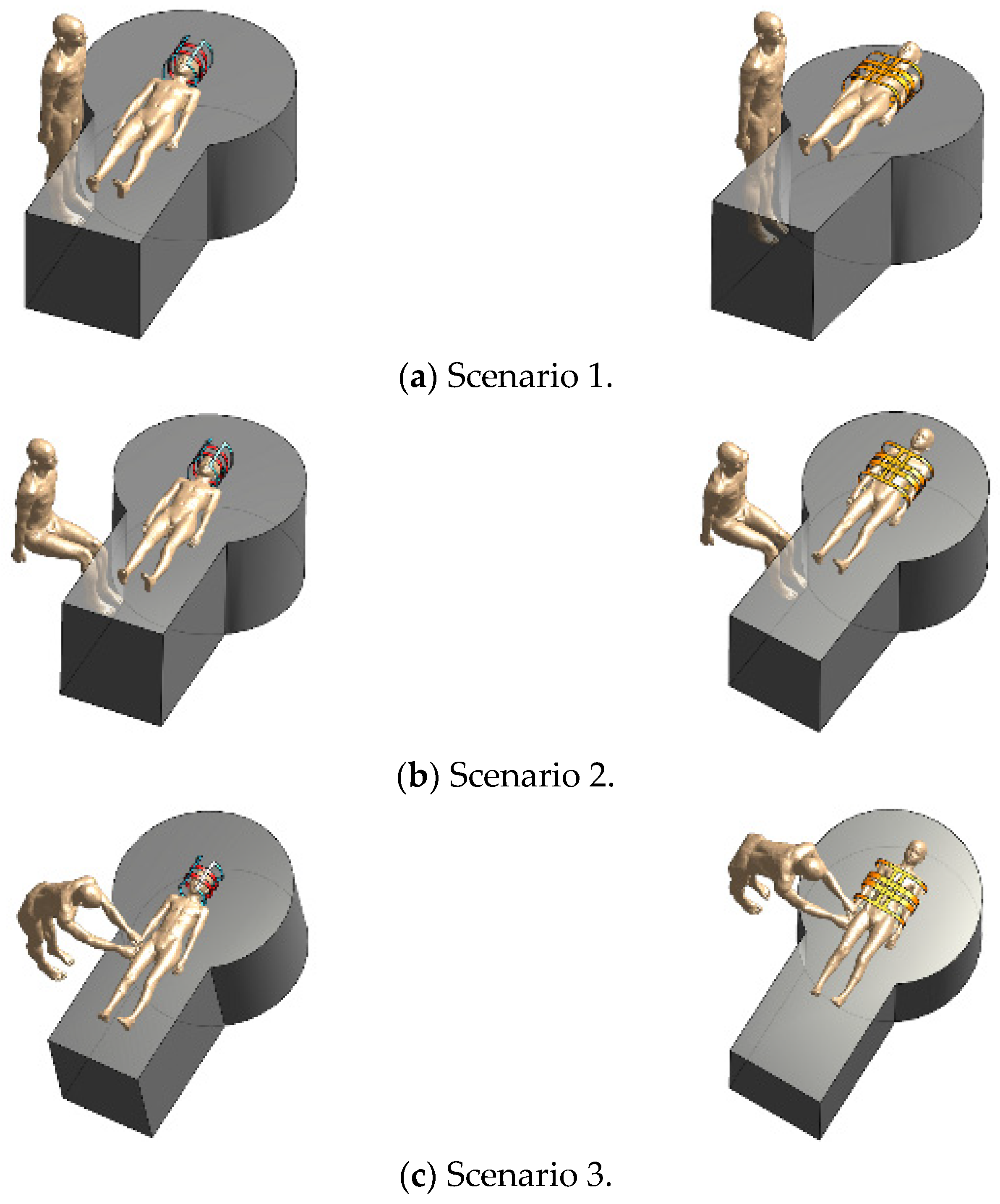
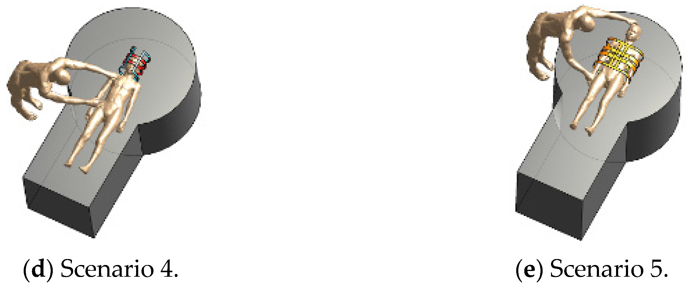
2.3. Assessment Scenarios

The RF EMF exposure was assessed according to the following five representative scenarios for different patient assistant poses using the previously defined head and body coils. Scenario 1 is a posture in which the patient assistant is standing next to the patient. Scenario 2 is a posture in which the patient assistant is sitting next to the patient. Scenario 3 is a posture in which the patient assistant’s hands are placed on the patient’s hand. As previously mentioned regarding the head and body RF coils in this study, scenarios 1–3 assess both RF coils equally. However, scenario 4 is for the head RF coil only, with a posture in which the patient assistant’s right hand holds the patient’s left hand, and the patient assistant’s left hand is on the patient’s chest. Finally, scenario 5 is for the body RF coil only, under a posture in which the patient assistant’s right hand holds the patient’s hand, and the patient assistant’s left hand is on the patient’s head. Compared to scenario 4, scenario 5 creates a larger electrical current loop owing to the patient assistant’s posture. The scenarios are summarized in Figure 5. The magnet and patient table were placed under each scenario to mimic realistic distances between the patient assistant and patient. Because the dielectric properties of the magnet and the patient table were considered to be those found in air, the presence of the magnet and patient table did not affect the SAR assessments. Additionally, the patient assistant is absent in scenario Sab. For the SAR assessments of each scenario, 1 and 10 g averaged SARs were calculated using 1 W of scaled input power. The numerical simulations of each scenario were conducted on a 64-bit PC with 192 GB of RAM and an Intel Xeon 6226 CPU equipped with an NVIDIA Quadro RTX 8000 GPU. The grid size of the human body models was 2 × 2 × 2 mm3. The computation time of each of the five scenarios took approximately 12–20 h, depending on the total number of grids used in each scenario.

3. Results and Discussion

The conditions and amount of RF exposure are dependent on the desired image contrast, RF coils used, and target body parts. In an MRI system, the image contrast can be adjusted by applying different RF powers (resulting different flip angle) to the subject [27]. The RF exposure levels are also dependent on the loaded body parts because more loading in a RF coil requires additional RF power to flip the spins at a specific angle for the desired MRI scans [28]. In this study, 1 W normalized RF power was applied to all SAR computations for each scenario, which is a commonly applied method for the numerical assessment of RF energy deposition in an MRI system [29,30,31]. This helps with analytical comparisons of SAR computations under different MRI scan protocols requiring different levels of RF power.
Meanwhile, there are a few factors that can affect the RF exposure of the patient assistant during MRI scans: (1) the distance of the patient assistant from the RF coils or patients, (2) the poses of patient assistant, (3) the dielectric tissue properties of the patient assistant and patients, and (4) the different conditions of the electrical current flow within the patient assistant, which is induced by the EMF of the RF coils.
The maximum values (so-called ‘hot-spots’) of 1 g peak averaged SARs in the Billie and Thelonious heads were 1.67 and 1.62 W/kg, respectively, when loaded in the head RF coil. The maximum SAR values were observed at the nose. For the body RF coil, the maximum values of 1 g peak averaged SARs in Billie and Thelonious were 0.87 and 1.16 W/kg respectively, found at the center of the back. The existence and poses of the patient assistant did not notably affect the SAR levels of the patient because the patient assistant was located outside of the RF coils. The difference in the SARs of the patient’s head/body was below 1.5% when the patient assistant was involved, as summarized in Table 2, Table 3, Table 4 and Table 5. In addition to scenarios 1–5, note that Sab was defined in Table 2, Table 3, Table 4 and Table 5 for the absence of a patient assistant.
Figure 6a–d shows the 1 g averaged SAR distribution in the patient assistant when the patient (Billie) was loaded in the head RF coil, whereas Figure 6e shows the 1 g SAR distribution when the body RF coil was used. The patient did not notably affect the hot-spot locations of the patient assistant in this study. The hot-spots in each scenario were observed at different locations on the patient assistant. The levels of the hot-spots also depended on the patient assistant’s location and pose. For scenario 1, the hot spot was found at the abdomen, which is close to the head/body RF coils. For a similar reason, the hot-spot in scenario 2 was found at the thigh. The levels of scenarios 1 or 2 were relatively lower than those of scenarios 3–5 mainly because of (1) the physical distance from the RF coils to the patient assistant and (2) the lack of electrical contact points between the patient assistant and patient.
Meanwhile, when the patient assistant made direct contact with the patient as in scenarios 3–5 (see Figure 5c–e), the hot-spots were clearly observed at the patient assistant’s hand because a substantially induced electrical current was driven through the patient assistant’s arms, forming electrical closed loops. For this reason, compared with scenarios 1 and 2, the overall SAR levels of the patient assistant were significantly increased in scenarios 3–5. The external magnetic field generated by the RF coils was coupled to the closed induction loop formed by the arms of the patient assistant. This therefore caused an induction current along the patient assistant’s arm, and thus a notably increased SAR in the patient assistant’s body was observed. The level of hot-spot tended to have a relationship depending on the formation of the loops formed by the body parts of the patient assistant and patient or gaps between them. According to Faraday’s law, the magnetic field induced an electromotive force in these effective conduction loops, thereby generating an electrical current proportional to the area of the loop and magnetic flux. Larger loops result in a higher induction current. Therefore, scenario 5 produced higher SAR levels in the patient assistant than scenarios 4 and 3, because the largest loop size was formed under scenario 5.
In most cases, the SAR levels of the patient assistant were much lower than those of the patient’s head or body, except under scenario 5, which had the largest loop formed by the patient assistant’s arm. In this scenario, the SAR levels of the patient assistant were close to 90.5% those of the patient, as shown Table 5. As the patient’s body size decreases, the poses or contact position of the patient assistant with the patient become located closer to the RF coils, and thus the SAR levels of the patient assistant become more similar to those of the patient. If the subject of the MRI scan is a neonate/child or pet (e.g., dog, cat), it is more likely that the MRI scan will be accompanied by a patient assistant. Therefore, in these cases, the patient assistant should be particularly careful and aware of the RF energy exposure. Furthermore, more careful attention is required if the field strength (B0) of an open MRI system is increased (up to 1.2 Tesla, www.hitachi-medical-systems.eu/products/mri/oasis-12t.html (Accessed on 28 May 2021) because the overall SAR level tends to increase in proportion to the square of the increase in B0 [32]. That is, when the field strength of the open MRI system increases, it can be predicted that the SAR level for the patient assistant having the same pose as in scenario 5 will be much higher. Therefore, although the ICNIRP guidelines for EMF protection [4] are not currently applied to patient assistants, the results of this study suggest that open MRI systems require the preparation of safety rules for them as well.

4. Conclusions

In this study, we investigated the level of RF energy exposure under various patient assistant poses using the head and body RF coils for an open MRI system. Although a lower risk of RF energy exposure is incurred in low-field MRI systems, there may be situations in which an MRI scan can be performed with a patient assistant nearby. The safety of the patient assistant with respect to EMFs in open MRI systems is an important factor, and thus the RF safety assessment needs to be carefully defined to see how significantly the SAR level will increase under specific conditions, including patient assistant poses, distance to the RF coils, and configurations of interventional treatments during MRI scans. For this reason, in this paper, different exposure scenarios for a patient assistant were derived and the assistant’s EMF exposure was analyzed. The larger the loop size between the patient and patient assistant, and the closer the contact position between the patient and patient assistant is to the RF coil, the higher the SAR levels created for the patient assistant. To protect the patient assistant during MRI scans, particularly in open MRI systems, it is necessary to consider the loop formation and contact locations for both the patient and patient assistant. Additional worst-case patient assistant poses are worth investigating.

Author Contributions

Conceptualization, S.-E.H. and S.O.; methodology, S.-E.H., S.O., and H.-D.C.; validation, S.-E.H. and S.O.; formal analysis, S.-E.H. and S.O.; investigation, S.-E.H. and S.O.; resources, S.-E.H. and S.O.; data curation, S.-E.H. and S.O.; writing—original draft preparation, S.-E.H., S.O., and H.-D.C.; writing—review and editing, S.-E.H. and S.O.; visualization, H.-D.C.; project administration, H.-D.C.; funding acquisition. All authors have read and agreed to the published version of the manuscript.

Funding

This work was supported by the ICT R&D program of MSIT/IITP (2019-0-00102, A Study on Public Health and Safety in a Complex EMF Environment).

Institutional Review Board Statement

Not applicable.

Informed Consent Statement

Not applicable.

Data Availability Statement

Not applicable.

Conflicts of Interest

The authors declare no conflict of interest.

References

  1. Webb, A.; Collins, C.M. Parallel transmit and receive technology in high-field magnetic resonance neuroimaging. Int. J. Imaging. Syst. Technol. 2010, 20, 2–13. [Google Scholar] [CrossRef]
  2. ICNIRP. 1998 Guidelines for limiting exposure to time-varying electric, magnetic and electromagnetic fields (up to 300 GHz). Health Phys. 1998, 74, 494–522. [Google Scholar]
  3. ICNIRP. 2010 Guidelines for limiting exposure to time-varying electric, magnetic and electromagnetic fields (1 Hz to 100 kHz). Health Phys. 2010, 99, 816–836. [Google Scholar]
  4. ICNIRP. 2020 Guidelines for limiting exposure to time-varying electric, magnetic and electromagnetic fields (100 kHz to 300 GHz). Health Phys. 2020, 118, 483–524. [Google Scholar]
  5. ICNIRP. 2009 Statement Amendment to the ICNIRP 2009 statement on medical magnetic resonance (MR) procedures: Pro-tection of patients. Health Phys. 2009, 97, 259–261. [Google Scholar]
  6. IEC. IEC 60601-2-33: Medical Electrical Equipment-Part 2-33: Practical Requirements for the Safety of Magnetic Resonance Equipment for Medical Diagnosis; IEC: Geneva, Switzerland, 2015; Chapter 201.12. [Google Scholar]
  7. Rianne, S.; Sachiko, Y.-S. Occupational exposure to electromagnetic fields from medical sources. Ind. Health 2018, 56, 96–105. [Google Scholar]
  8. Rathebe, P.; Weyers, C.; Raphela, F. A health and safety model for occupational exposure to radiofrequency fields and static magnetic fields from 1.5 and 3 T MRI scanners. Health Technol. 2020, 10, 39–50. [Google Scholar] [CrossRef]
  9. Huss, A.; Özdemir, E.; Schaap, K.; Kromhout, H. Occupational exposure to MRI-related magnetic stray fields and sleep quality among MRI–Technicians–A cross-sectional study in the Netherlands. Int. J. Hyg. Environ. Health 2021, 231, 113636. [Google Scholar] [CrossRef]
  10. Murbach, M.; Neufeld, E.; Kainz, W.; Pruessmann, K.P.; Kuster, N. Whole-body and local RF absorption in human modles as a function of anatomy and position within 1.5T body coil. Magn. Reson. Med. 2013, 71, 839–845. [Google Scholar] [CrossRef] [PubMed]
  11. Seo, J.H.; Noh, Y.; Kim, K.-N.; Ryu, Y.C. Evaluation of the specific absorption rate for simultaneous multi frequency RF ex-citation in 7-T magnetic resonance imaging. J. Magn. 2017, 637–641. [Google Scholar] [CrossRef]
  12. Liu, W.; Wang, H.; Zhang, P.; Li, C.; Sun, J.; Chen, Z.; Xing, S.; Liang, P.; Wu, T. Statistical evaluation of radiofrequency ex-posure during magnetic resonant imaging: Application of whole-body individual human model and body motion in the coil. Int. J. Environ. Res. Public Health 2019, 16, 1069. [Google Scholar] [CrossRef] [Green Version]
  13. Fujimot, K.; Angelone, L.M.; Lucano, E.; Rajan, S.S.; Lacono, M.I. Radio-frequency safety assessment of stents in Blood Ves-sels During Magnetic Resonance Imaging. Front. Physiol. 2018, 9, 1439. [Google Scholar] [CrossRef] [Green Version]
  14. Golestanirad, L.; Rahsepar, A.A.; Kirsch, J.E.; Suwa, K.; Collins, J.C.; Angelone, L.M.; Keil, B.; Passman, R.S.; Bonmassar, G.; Serano, P.; et al. Changes in the specific absorption rate (SAR) of ra-diofrequency energy in patients with retained cardiac leads during MRI at 1.5 T and 3 T. Magn. Reson. Med. 2019, 81, 653–669. [Google Scholar] [CrossRef]
  15. Rahsepar, A.A.; Zimmerman, S.L.; Hansford, R.; Guttman, M.A.; Castro, V.; McVeigh, D.; Kirsch, J.E.; Halperin, H.R.; Nazarian, S. The Relationship between MRI Radiofrequency Energy and Function of Nonconditional Implanted Cardiac Devices: A Prospective Evaluation. Radiology 2020, 295, 307–313. [Google Scholar] [CrossRef]
  16. Seo, Y.; Wang, Z.J. Measurement and evaluation of specific absorption rate and temperature elevation caused by an artificial hip joint during MRI scanning. Sci. Rep. 2021, 11, 1–12. [Google Scholar] [CrossRef]
  17. Malik, S.J.; Beqiri, A.; Price, A.N.; Teixeira, J.N.; Hand, J.W.; Hajnal, J.V. Specific absorption rate in neonates undergoing magnetic resonance procedures at 1.5 T and 3 T. NMR Biomed. 2015, 28, 344–352. [Google Scholar] [CrossRef] [PubMed] [Green Version]
  18. Murbach, M.; Neufeld, E.; Samaras, T.; Córcoles, J.; Robb, F.J.; Kainz, W.; Kuster, N. Pregnant women models analyzed for RF exposure and temperature increase in 3T RF shimmed birdcages. Magn. Reson. Med. 2017, 77, 2048–2056. [Google Scholar] [CrossRef] [PubMed]
  19. Barrera, C.A.; Francavilla, M.L.; Serai, S.D.; Edgar, J.C.; Jaimes, C.; Gee, M.S.; Roberts, T.P.L.; Otero, H.J.; Adzick, N.S.; Victoria, T. Specific Absorption Rate and Specific Energy Dose: Comparison of 1.5-T versus 3.0-T Fetal MRI. Radiology 2020, 295, 664–674. [Google Scholar] [CrossRef] [PubMed]
  20. Marques, J.P.; Simonis, F.F.; Webb, A.G. Low-field MRI: An MR physics perspective. J. Magn. Reson. Imaging 2019, 49, 1528–1542. [Google Scholar] [CrossRef] [PubMed] [Green Version]
  21. Giovannetti, G.; Frijia, F.; Flori, A.; Montanaro, D. Design and simulation of a Helmholtz coil for magnetic resonance imag-ing and spectroscopy experiments with a 3T MR clinical scanner. Appl. Magn. Reson. 2019, 50, 1083–1097. [Google Scholar] [CrossRef]
  22. Tomanek, B.; Volotovskyy, V.; Tyson, R.; Yin, D.; Sharp, J.; Blasiak, B. A quadrature volum RF coil for vertical B0 field open MRI systems. Concepts. Magn. Reson. Part B 2016, 46B, 118–122. [Google Scholar]
  23. Christ, A.; Kainz, W.; Hahn, E.G.; Honegger, K.; Zefferer, M.; Neufeld, E.; Rascher, R.W.; Janka, W.; Bautz, J.; Chen, B.; et al. The virtual fami-ly-development of surface-based anatomical models of two adults and two children for dosimetric simulations. Phys. Med. Biol. 2010, 55, N23–N38. [Google Scholar] [CrossRef] [PubMed]
  24. Gosselin, M.-C.; Neufeld, E.; Moser, H.; Huber, E.; Farcito, S.; Gerber, L.; Jedensjö, M.; Hilber, I.; Gennaro, F.D.; Lloyd, B.; et al. Development of a new generation of high-resolution anatomical models for medical device evaluation: The Virtual Population 3. Phys. Med. Biol. 2014, 59, 5287–5303. [Google Scholar] [CrossRef] [PubMed]
  25. Hasgall, P.; Di Gennaro, F.; Baumgartner, C.; Neufeld, E.; Lloyd, B.; Gosselin, M.C.; Payne, D.; Klingenböck, A.; Kuster, N. IT’IS Database for Thermal and Electromagnetic Parameters of Biological Tissues, 4th ed. Available online: https://itis.swiss/virtual-population/tissue-properties/downloads/ (accessed on 28 May 2021).
  26. Gabriel, S.; Lau, R.W.; Gabriel, C. The dielectric properties of biological tissues: III. Parametric models for the dielectric spectrum of tissues. Phys. Med. Biol. 1996, 41, 2271–2293. [Google Scholar] [CrossRef] [PubMed] [Green Version]
  27. Wang, Z.; Lin, J.; Mao, W.; Liu, M.; Smith, M.B.; Collins, C.M. SAR and temperature: Simulations and comparison to regula-tory limits for MRI. J. Magn. Reson. Imaging. 2007, 26, 437–441. [Google Scholar] [CrossRef] [Green Version]
  28. Collins, C.M.; Liu, W.; Wang, J.; Gruetter, R.; Vaughan, J.T.; Ugurbil, K.; Smith, M.B. Temperature and SAR calculations for a human head within volume and surface coils at 64 and 300 MHz. J. Magn. Reson. Imaging 2004, 19, 650–656. [Google Scholar] [CrossRef]
  29. Vaughan, J.T.; Snyder, C.J.; DelaBarre, L.J.; Bolan, P.J.; Tian, J.; Bolinger, L.; Adriany, G.; Andersen, P.; Strupp, J.; Ugurbil, K. Whole-body imaging at 7T: Preliminary results. Magn. Reson. Med. 2009, 61, 244–248. [Google Scholar] [CrossRef] [Green Version]
  30. Wang, J.; Mao, W.; Qiu, M.; Smith, M.B.; Constable, R.T. Factors influencing flip angle mapping in MRI: RF pulse shape, slice-select gradients, off-resonance excitation, and B0 inhomogeneities. Magn. Reson. Med. 2006, 56, 463–468. [Google Scholar] [CrossRef]
  31. Chou, C.K.; Bassen, H.; Osepchuk, J.; Balzano, Q.; Peterson, R.; Meltz, M.; Cleveland, R.; Lin, J.C.; Heynick, L. Radio frequency electromagnetic exposure: Tutorial review on experimental dosimetry. Bioelectromagnetics 1996, 17, 195–208. [Google Scholar] [CrossRef]
  32. Collins, C.M.; Wang, Z. Calculation of radiofrequency electromagnetic fields and their effects in MRI of human subjects. Magn. Reson. Med. 2011, 65, 1470–1482. [Google Scholar] [CrossRef] [PubMed]
Figure 1. Geometry and dimensions of the numerically modeled head RF coil in a 0.3 Tesla open MRI system.
Applsci 11 04967 g001
Figure 2. Circularly polarized (CP) excitation magnetic field (B1 in Tesla) of the head RF coil model under the unloaded condition.
Applsci 11 04967 g002
Figure 3. Geometry and dimensions of the numerically modeled body RF coil in a 0.3 Tesla open MRI system.
Applsci 11 04967 g003
Figure 4. Circularly polarized (CP) excitation magnetic field (B1 in Tesla) of the body RF coil model under the unloaded condition.
Applsci 11 04967 g004
Figure 5. Assessment scenarios of RF energy exposure: The patient assistant (a) stands next to the patient (scenario 1), (b) sits by the patient (scenario 2), (c) holds the patient’s hand (scenario 3), (d) holds the patient’s hand and chest (head coil case, scenario 4), and (e) holds the patient’s hand and head (body coil case, scenario 5).
Applsci 11 04967 g005aApplsci 11 04967 g005b
Figure 6. The 1 g SAR distributions of the patient assistant (Duke) when Billie was the patient for different scenarios: (a) 1, (b) 2, (c) 3, (d) 4, (e) 5 (same dB and color scale).
Applsci 11 04967 g006
Table 1. Human body models.
NameAgeSexHeight (cm)Mass (kg)BMI (kg/m2)Tissues (No.)
Patient assistantDuke34 yM1747023.177
PatientBillie11 yF1463616.775
PatientThelonious6 yM1172014.276
Table 2. Peak spatially averaged SAR (W/kg) in Billie (patient) and Duke (patient assistant) according to head RF coil (input power = 1 W).
ScenarioPatient (Billie)Patient assistant (Duke)
1 g10 g1 g10 g
Sab1.66701.0411--
11.69601.05960.000380.00019
21.68881.05510.000160.00008
31.66141.03800.003530.00162
41.65831.03590.199280.09240
Table 3. Peak spatially averaged SAR (W/kg) in Thelonious (patient) and Duke (patient assistant) according to head RF coil (input power = 1 W).
ScenarioPatient (Thelonious)Patient Assistant (Duke)
1 g 10 g 1 g 10 g
Sab1.65000.8279--
11.66630.83610.000480.00024
21.62630.84770.000190.00009
31.59920.83360.002640.00141
41.58110.82420.265370.082449
Table 4. Peak spatially averaged SAR (W/kg) in Billie (patient) and Duke (patient assistant) according to body RF coil (input power = 1 W).
ScenarioPatient (Billie)Patient Assistant (Duke)
1 g10 g1 g10 g
Sab0.86490.5684--
10.87440.57460.000170.00007
20.87520.57520.000070.00003
30.87130.57260.036350.01294
50.85920.56650.2273010.15065
Table 5. Peak spatially averaged SAR (W/kg) in Thelonious (patient) and Duke (patient assistant) according to RF body coil (input power = 1 W).
ScenarioPatient (Thelonious)Patient Assistant (Duke)
1 g10 g1 g10 g
Sab1.27950.7457--
11.13110.76380.000290.00016
21.28870.75640.000120.00006
31.10000.67710.069780.03815
51.04450.68280.945680.41197
Publisher’s Note: MDPI stays neutral with regard to jurisdictional claims in published maps and institutional affiliations.

