1. Introduction
As a new type of material with a photonic band gap, photonic crystals play an important role in modern optical systems, such as photonic crystal fibers, waveguides, low-threshold lasers, multifunctional sensors, cavity quantum electrodynamics, and quantum information processing [
1,
2,
3,
4,
5,
6]. Over the past decades, many techniques have been developed for the fabrication of photonic crystals, of which the laser interference lithography (LIL) is a powerful technology due to its low cost, short time consumption, and lack of necessity for precise focusing. LIL was first used to fabricate one-dimensional (1D) grating using double-beam interference. With the addition of a third or further beams, 2D and 3D lattice interference patterns can be generated, including all 2D and 3D Bravais lattice structures [
7,
8,
9,
10,
11].
Since the energy of the interference fringes is sinusoidally distributed, a high-contrast LIL can write sub-diffraction-limited features in photoresist [
12,
13]. This is possible because of the non-linear response of positive photoresist to the light dose. The feature size (line width) is reduced by overexposing the high-contrast sinusoidal energy distribution light field [
14,
15]. Therefore, the actual limit of the line width is set by the light field contrast and the sensitivity of the photoresist. In order to obtain the smallest possible feature size, the contrast of the interference light field needs to be sufficiently high. To ensure sufficient interference contrast, the design of the interferometer and the selection of the beam parameters are crucial.
As shown in the following papers [
16,
17,
18], the source of the contrast loss of the double-beam interference in the same plane mainly includes the beam pointing deviation, the polarization state, and the intensity ratio of the interference beam. Different from double-beam interference, multi-beam interference lithography (MIL) is the superposition of the intensity of multiple groups of non-coplanar interference with different periods, directions, and extremum [
19,
20,
21]. The value of the incident angle controls the period of the interference pattern. For non-coplanar interference, the contrast of the interference light field is simultaneously affected by the azimuth angle, incident angle, and polarization state of each beam [
22,
23,
24]. Therefore, it is necessary to select a suitable combination of beam polarization states for different incident angles to obtain the best contrast and consider the influence of the beam pointing stability on the contrast under that incident combination.
In this paper, we discuss the two-beam non-coplanar interference, study the relationship between fringe visibility and the spatial incidence direction of the two beams, and analyze the source of the contrast loss in the non-coplanar interference. We calculate how to select the appropriate combination of beam polarization states to ensure sufficient contrast under different incident angles. Then, according to the non-coplanar interference model, we demonstrate the specific beam polarization combinations that should be used for different pattern periods in three-beam LIL. Although the focus of this paper is three-beam LIL, the same analysis of contrast loss and the beam polarization combination mode is applicable for N-beam (n > 3) interference lithography.
2. Contrast in Double-Beam Non-Coplanar Interference Patterns
When two laser beams from the same light source coincide, an interference pattern is produced, which contains all of the information including the intensity and phase of the two interfering beams. The interference of two beams is the superposition of electric field vectors. The electric field vector of
ith beam vector can be written as
where
is the amplitude,
is the polarization vector,
is the wave propagation vector,
is the position vector at interference area, and
is the initial phase of the light wave. The intensity of two-beam interference can be calculated as follows:
Interference contrast is defined as
and
represent the minimum and the maximum intensity of the interference field. Substituting Equation (2) into Equation (3) yields
Equation (4) states that contrast is affected by the intensity mismatch and the polarization states for each beam. We already know that the contrast loss caused by the unequal amplitude of the two beams is very low. Even if the amplitude ratio of the two beams reaches 2:3, the contrast loss is only 0.076. Therefore, the main source of contrast loss for non-coplanar interference is the polarization state of the two beams.
In Equation (1), according to the coordinate rotation transformation matrix
can be expressed as
Here,
and
are the azimuthal angle and the incident angle, respectively;
is the polarization angle;
is the wavenumber; and
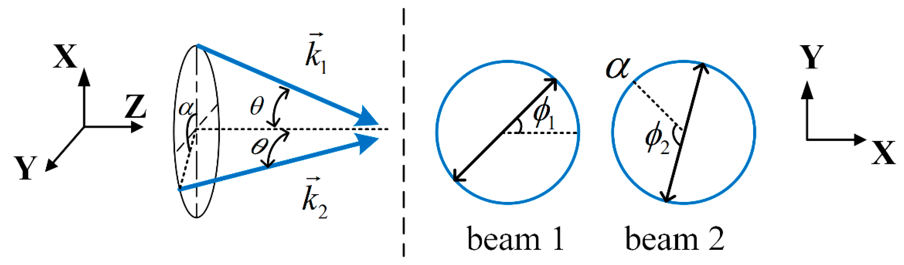
is the wavelength of the laser. As shown in
Figure 1, the azimuth angles of the two non-coplanar coherent beams are
and
, and they incident at the identical angle
. When
is equal to
, it turns into coplanar interference. Using Equations (5)–(7), the contrast for two-beam interference can be further reduced to
Equation (8) shows that for different azimuth and incident angles, we need to choose different beam polarization modes to maximize the contrast of the interference field.
Owing to the incident surfaces of the two light waves not being coplanar, there is no case where the horizontal polarization component is totally in the same direction. We can only reduce the contrast loss by ensuring that their co-directional TE vibration components achieve the maximum value. Under this condition, the azimuth and the polarization angles of the two beams satisfy the following equation:
In this case, the contrast can simplify to
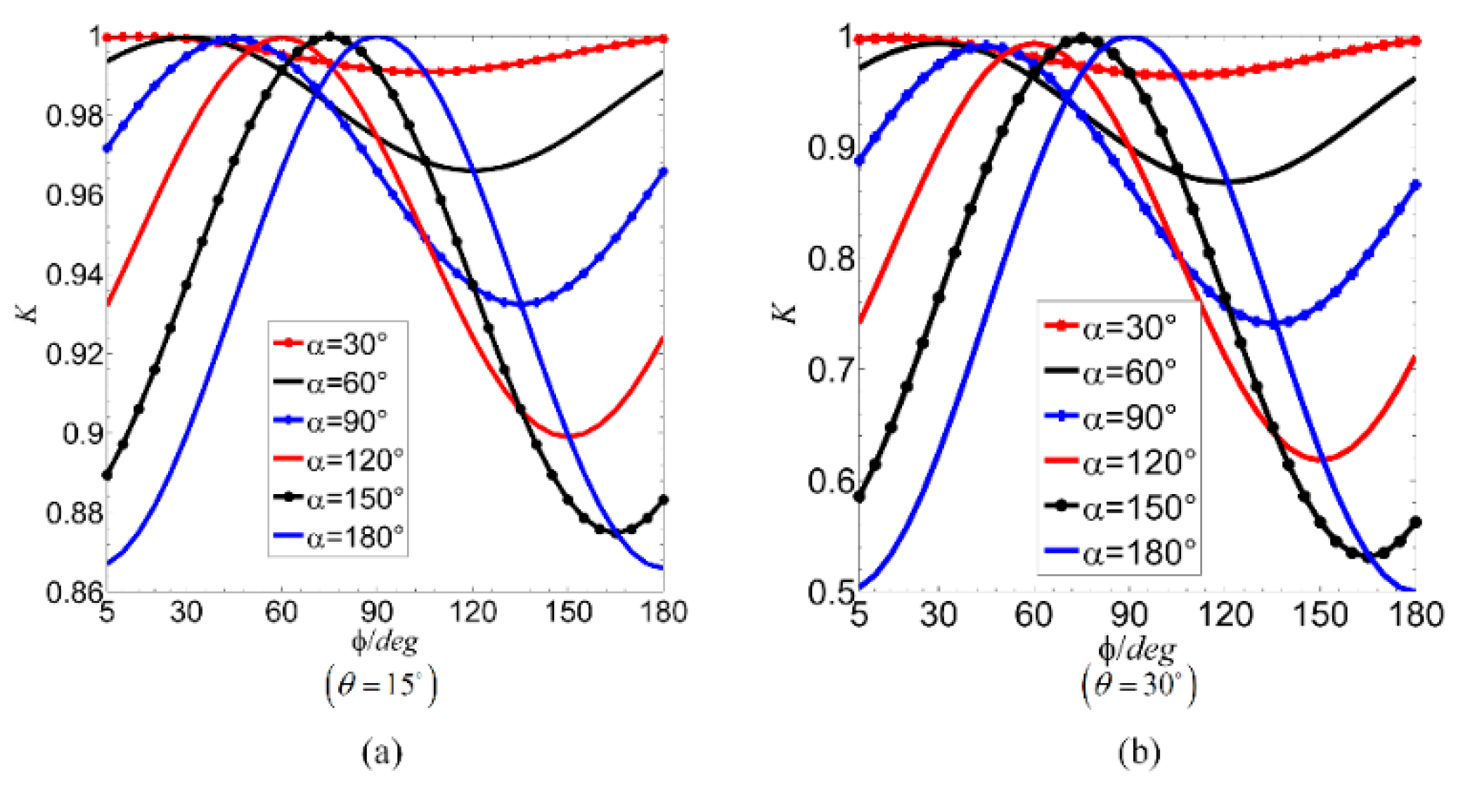
From Equation (10), each azimuth angle has a unique polarization co-direction angle corresponding to it, which causes the contrast to obtain a maximum value. We can calculate that the condition for maximum contrast is
This condition is verified in
Figure 2. We simulated the contrast of all linear polarization orientations when the azimuth angles were 30°, 60°, 90°, 120°, 150°and 180°, and found that the corresponding polarization angle when the maximum contrast is achieved was 15°, 30°, 45°, 60°, 75°, and 90°. This shows that when the polarization angle is on the intersection of the vibration planes of two waves, the contrast is maximized. By comparing
Figure 2a,b, it can be seen that the polarization orientation has a great influence on the contrast, especially under the condition of a large angle of incidence.
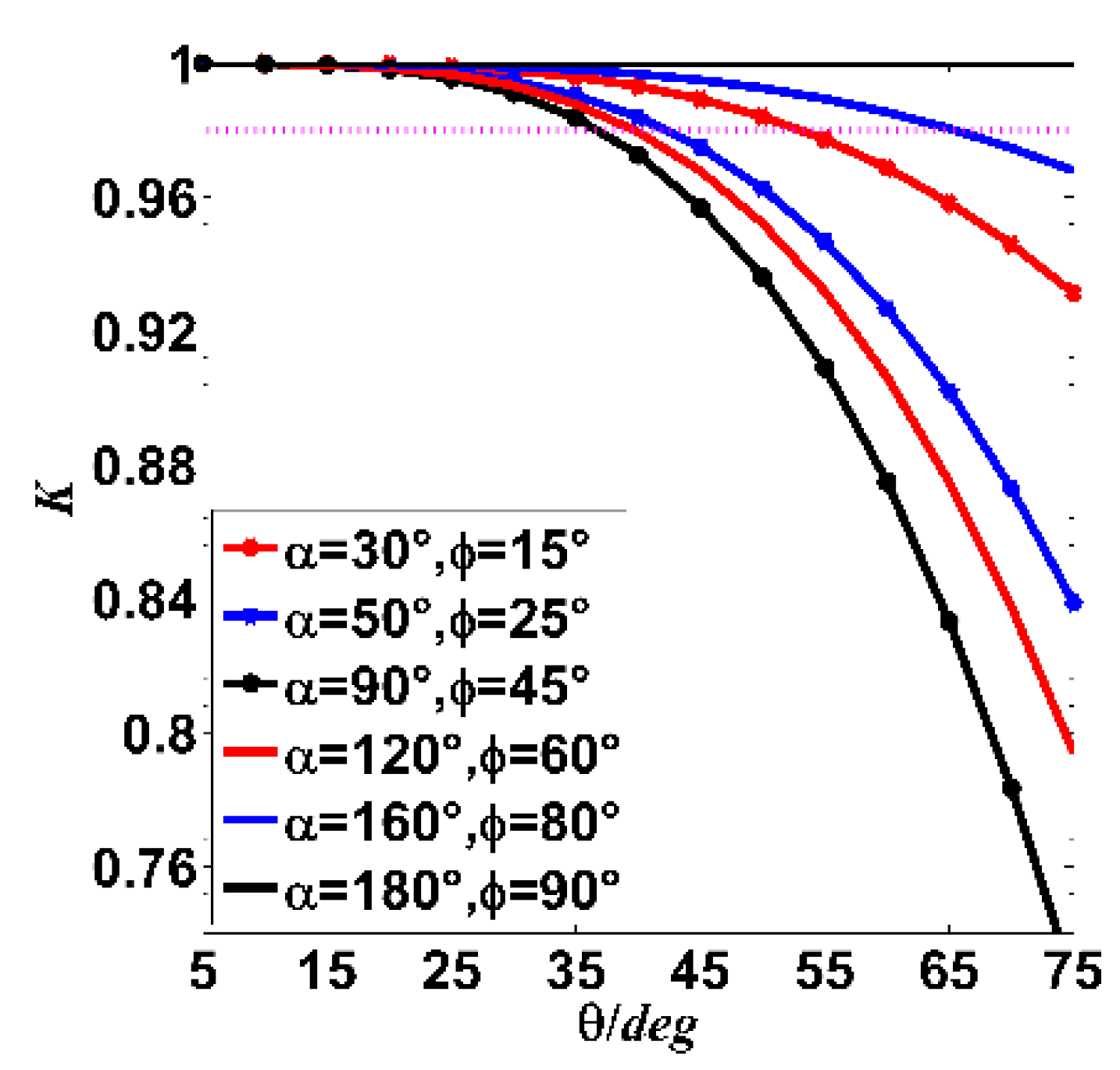
Substituting Equation (11) into Equation (10), the maximum contrast that can be achieved by double-beam interference is
As shown in
Figure 3, only in the case of coplanar interference
and where two beams are incident in
TE-
TE mode will the contrast not decrease due to the increase in the incident angle. As the azimuth angle increases, the contrast loss caused by large incident angle interference is considerable until it increases to 90°, where the contrast loss caused by large incident angle interference reaches the maximum. When the azimuth angle continues to increase beyond 90°, the contrast loss gradually decreases. Until coplanar interference is reached, the contrast loss caused by the large incident angle completely disappears. As long as the incident angle is not greater than 35°, the contrast loss of any azimuth non-coplanar interference does not exceed 0.02. However, if the incident angle continues to increase, the contrast sharply decreases.
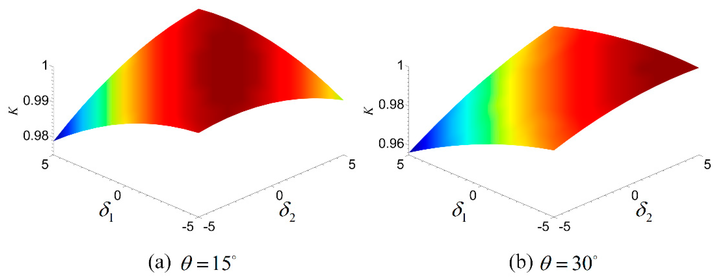
In addition, the existence of polarization angle deviation will inevitably cause the loss of contrast. To illustrate this impact, we assume that the polarization angle deviations of the two beams are
and
. In this case, the contrast can be described as
Under the same incident angle, the contrast loss is largest when the azimuth angle is equal to 90°. The polarization angle deviation at this point further increases the contrast loss. As shown in
Figure 4a,b, when the polarization angle deviation of the two beams reaches 5°, the greater the incident angle, the greater the loss of contrast.
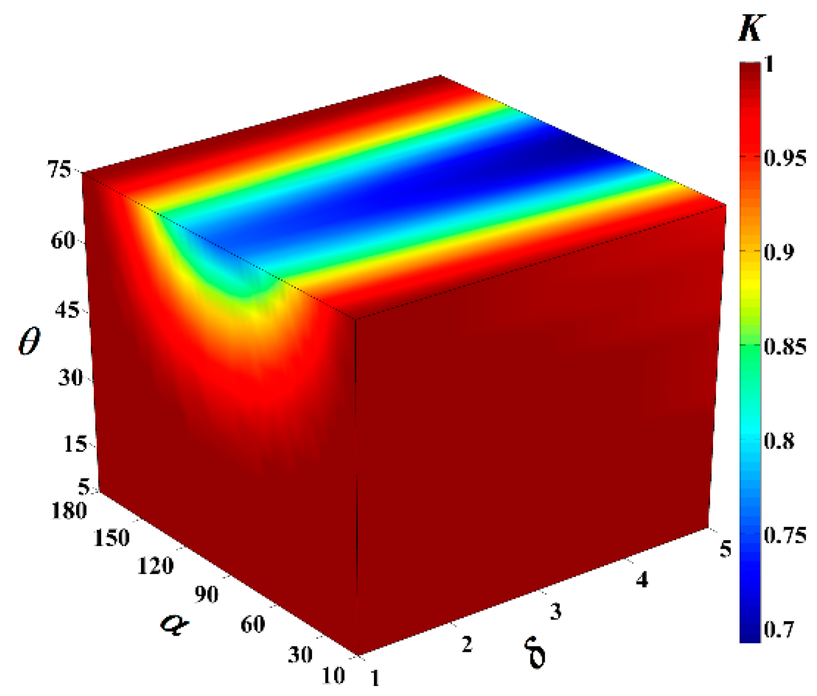
The incident angle, azimuth, and polarization for non-coplanar interference contrast were analyzed in turn. As shown in
Figure 5, considering all factors at a time, we obtained the contrast of two-beam non-coplanar interference at different incident angles, azimuth angles, and polarization angle deviations. The Figure shows that the polarization orientation must be adjusted to reduce the contrast loss caused by the increase in the incident angle. The maximum co-directional polarization component mode is not suitable for large-angle incident situations.
3. Contrast in Three-Beam Interference Patterns
N-beam interference is the incoherent superposition of
groups of two-beam non-coplanar interference. Therefore, the above analysis of non-coplanar interference is applicable to
N-beam interference. The intensity of
N-beam interference can be calculated as
Regardless of the influence of amplitude and assuming that the initial phases are zero in Equation (14), substituting Equation (14) into Equation (3) yields
It can be seen from Equation (15) that the polarization combination of the beams has a key effect on the contrast of the light field. Three-beam interference is a typical case of N-beam interference, the related derivation process, and results are generally applicable in multi-beam interference. Therefore, this paper chooses three-beam interference as the contrast loss analysis model.
3.1. Co-Directional Component Polarization
When the polarization common component is the largest, the relationship between the azimuth and the polarization angle of N-beam interference is as follows:
where
is the polarization angle of the beam whose azimuth is zero. The polarization vector can be written as follows:
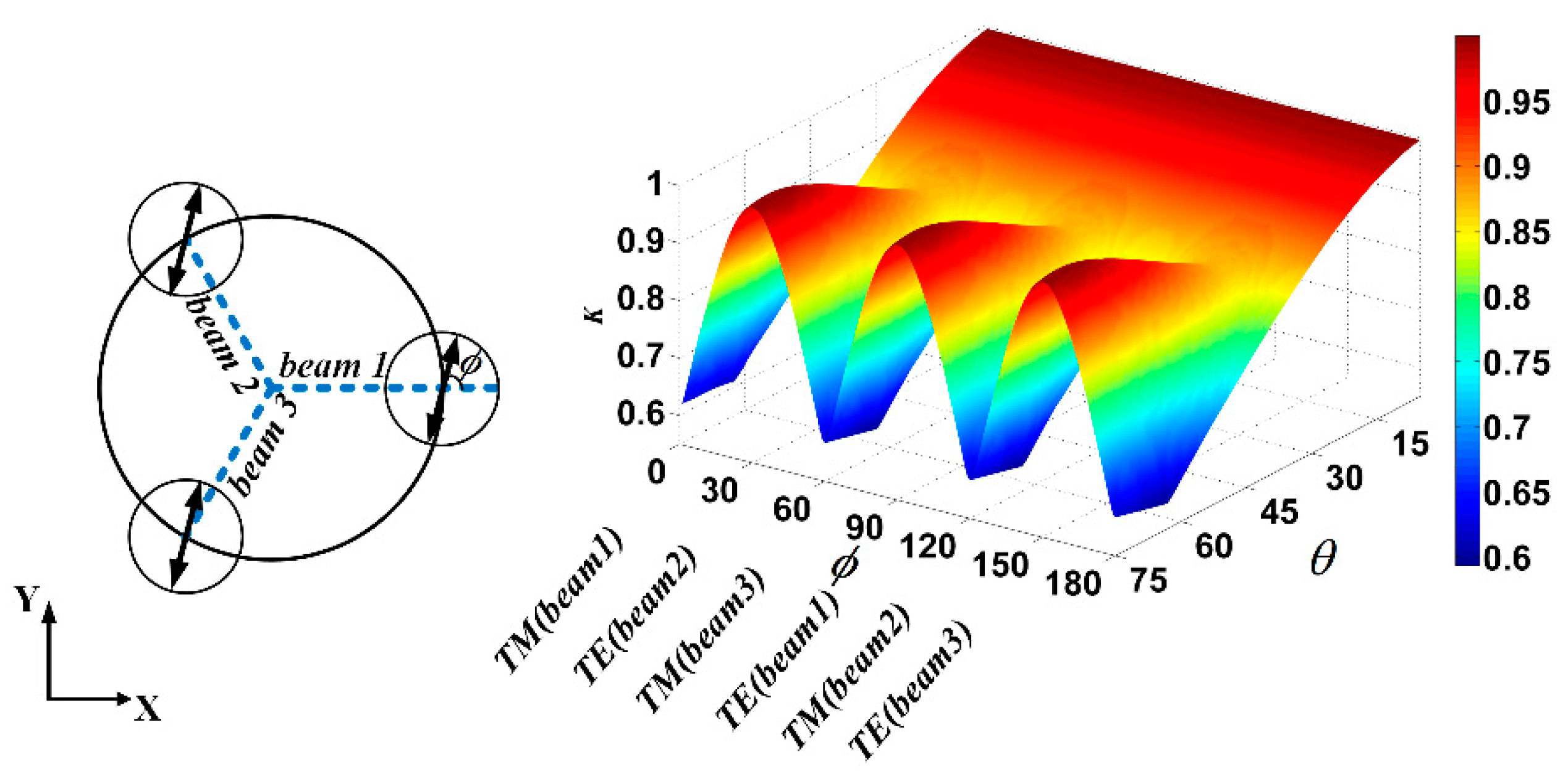
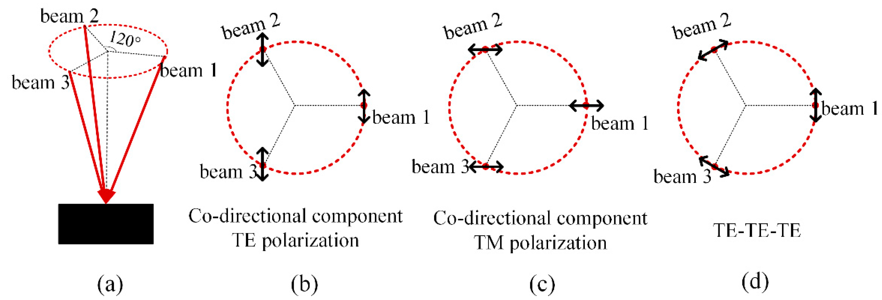
As shown in
Figure 6, the three incident beams follow a symmetrical configuration with the azimuth of
. The incident angles of the three beams are set as
. The polarization vectors of the three beams are
The three beams are symmetrically incident, and the vibration components of the x-y plane are along the same angle
. Substituting Equation (18) into Equation (15), considering the polarization and incident angle one at a time, the contrast as a function of two factors is plot in
Figure 6. Similar to the two-beam non-coplanar interference, when interfering at a small angle, the polarization angle will not change the contrast. The contrast loss will only increase as the incident angle increases. As the incident angle continues to increase, the contrast is more sensitive to the changes in the polarization angle and is extremely susceptible to polarization angle deviations.
In this case, taking the TE wave of one of the three beams as the common vibration direction can ensure that the contrast is sufficiently high even at a large incident angle. The polarization angle of beam 1 is
. From Equation (16), the polarization vectors can be expressed as
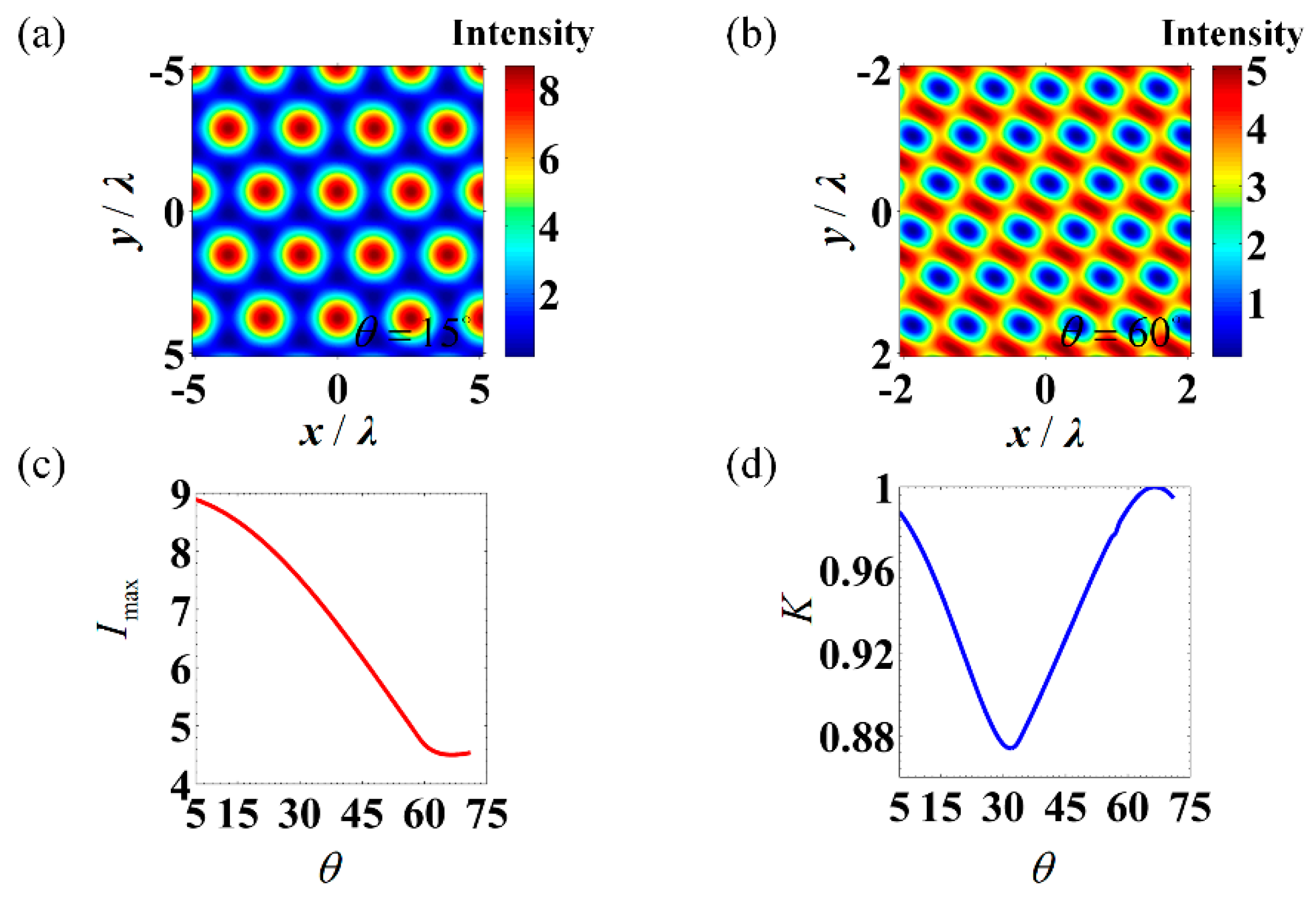
From Equation (14), the intensity distribution of three-beam interference can be calculated by
According to the above equation, the maximum intensity of the interference field is related to the value of the incident angle. As shown in
Figure 7, after the incident angle is increased to 32°, the contrast no longer decreases as the incident angle increases. At the same time, with the increase in incident angle, the pattern transitions from the hexagonal center maximum lattice to the hexagonal minimum lattice. The maximum value of the interference field intensity gradually decreases to half of the theoretical maximum value. This change in the maximum intensity value undoubtedly increases the difficulty of determining the exposure time in the photolithography process.
3.2. TE-TE-TE Polarization
Both co-directional component TE polarization and co-directional component TM polarization were analyzed above. In both cases, neither the high contrast of the light field nor the stability of the interference system can be guaranteed under the conditions of large-angle interference. As shown in
Figure 8d, another polarization mode is proposed for interference lithography under large-angle incidence.
When the polarization of the three beams are in
TE-TE-TE mode, the polarization angle of three beams is
. The polarization vectors can be expressed as
From Equation (14), the intensity distribution of three-beam interference can be calculated by
It can be observed from Equation (22) that the maximum intensity remains unchanged at 4.5 when the incident is in TE-TE-TE mode, which is only half of the theoretical value. The increase in the incident angle will not cause additional contrast loss and it makes it easier for us to control the exposure dose at different incident angles. Although the increase in exposure time may introduce additional environmental errors to the interference light field, it is clearly easier to obtain a pattern with a smaller feature size when the light field has a high contrast.
It can be seen from
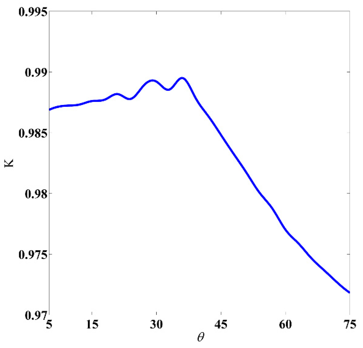
Figure 6 that the contrast loss caused by the polarization angle deviation must be considered, especially under the condition of large-angle interference. Under
TE-TE-TE incident condition, the polarization angle deviations are
, and the polarization angle of three beams are
. The polarization vector can be expressed as
It can be concluded from Equation (23) that when there is a deviation in the polarization angle, the contrast loss is related to the incident angle. Under the condition that the polarization angle deviations
are not more than ±5°, we calculated the minimum value of contrast when the incident angle is increased from 5° to 75°. As shown in
Figure 9, when the incident angle is not more than 40°, the contrast loss does not exceed 0.015. Even if the interference angle reaches 60°, the contrast still has 0.975. At this time, we have a sufficient contrast loss margin to consider the standing wave effect caused by large angle incidence.


