Abstract
We developed a mechanical power circulation test rig for a wind turbine gearbox with a power rating of 5.8 MW or less. The test rig consists of an electric motor, two auxiliary gearboxes, a torque-applying device, lubrication systems, cooling systems, and control systems. The torque generating device consists of a planetary gearbox and a hydraulic control system and is used to apply the desired torque to the test gearbox. The hydraulic control system applies the torque on the ring gear of the planetary gearbox. The gears and bearings of the two auxiliary gearboxes and planetary gearboxes met the design criteria for a safety factor of over 1.2 and a bearing life of 30,000 h. In addition, the master and slave gearboxes were connected to the test rig to verify whether the torque-applying device had applied variable torque in real-time during the test. The device was only able to induce a variable torque of up to 45.2 kN-m due to the limitation of the rated torque of the master and slave gearboxes. The test rig can test not only efficiency, vibration, and noise but also durability and overloading.
1. Introduction
A wind turbine drivetrain transfers mechanical energy from the rotor to the generator. It consists of main shaft, main bearing, a gearbox, and other components. Wind turbine gearboxes (WTGBs) that transfer input power (low speed and high torque) from a rotor to a generator (high speed and low torque) are expensive and generally recognized as a component with the highest failure rate among all other components in the drivetrain. Additionally, because WTGBs are installed in the narrow space of a nacelle, repair in the case of failure is costly and time-consuming. The design of a drivetrain influence not only the performance of the wind turbine but also durability. The service life of a wind turbine can be maintained at or extend beyond 20 years by reducing the failure rate of its drivetrain. The first step to reducing the failure rate is to investigate the performance of the WTGB (i.e., efficiency, noise, vibration, and durability). The reliability of a WTGB, measured in terms of performance and durability, can be evaluated through laboratory tests [1,2].
The test rig for WTGBs can be categorized into electrical and mechanical power circulation types, as shown in Figure 1 [3,4]. The major difference between the two test rigs is the type of power that is circulated through the system. In the case of electrical power circulation, an electric motor drives the input shaft of the test gearbox. Its output shaft is coupled to a generator that feeds the power back to the grid. In this way, the total energy consumption is significantly reduced [4]. However, in this type, when components such as motor, generator, and inverter are being selected, the total power required for the test, including the gearbox driving power, and the losses that occur at the gear/bearing must be considered. Because large and expensive motors, generators, and inverters are required to test large gearboxes, the initial cost of the test is high. Nevertheless, the advantages of this type include high accuracy and ease of torque control, and the test rig configuration is simple compared to the mechanical power circulation test rig.
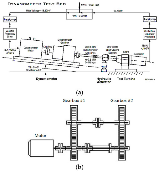
Figure 1.
Power circulation test rig for a wind turbine gearbox (WTGB). (a) Electrical type. (b) Mechanical type.
In the case of mechanical power circulation type, input and output shafts of two gearboxes with identical gear ratios are connected to each other by intermediate shafts and gearboxes, building a closed-loop. A torque-applying device can be included in the power loop. The applied torque loads both gearboxes. An external motor is used to rotate the system, which, in steady-state, must compensate only for the total power loss of the system. Therefore, its power rating is much lower than that which actually loads the gears. The degree of power circulation is controlled by the torque, which is applied by the torque-applying device and the motor speed. The advantage of this test rig is the significantly reduced installation cost because it does not require a generator and the driving motor only needs to be rated accordingly to the total power loss [4]. The disadvantage, however, is that the test rig becomes complex due to the addition of auxiliary devices (e.g., shaft, gearbox) to form the mechanical closed loop. Furthermore, the conventional test rig for a WTGB that uses mechanical power circulation uses an actuator installed in the torque arm of the gearbox to apply torque to its closed loop. In other words, because the torque-applying device is installed on the test gearbox, if the size or shape of the test gearbox is changed, the test rig should also be changed. Each mechanical power circulation test rig is designed to test WTGB of a certain specification. That is, there is no universal test rig that can test all WTGBs.
Arun et al. surveyed published papers on the construction and procedure of a test rig for noise, vibration, lubrication, cleanliness, and efficiency tests, using various test rigs of the two types. In addition, Aren et al. introduced a new compact test rig developed. This system is similar to the electrical power circulation-type test rig. The input of the gearbox is driven by a motor, and the output is torque induced into the gearbox by a pump. The torque can be changed during the test by adjusting the flow rate and pressure of the pump [5]. Mihailidis et al. introduced electrical and mechanical power circulation type test rigs. A method for applying torque to the mechanical power circulation-type test rig and a torque-applying device similar to a rotary actuator was introduced. This device was equipped with a two-stage planetary gear train and a motor, which was installed on the standard Forschungsstelle fur Zahnrader und Getriebebau of the Technical University Munich (FZG) back-to-back test rig. They also demonstrated that the test torque and rotation speed could be varied. However, they did not include the test results of their torque-applying device. It was also described as a method applicable to small mechanical power circulation-type test rigs [4]. Jung et al. introduced a failure analysis and test evaluation process for analyzing and evaluating the performance of a torque generator. The rig for the evaluation was of the electrical power circulation type, and the input was an electric motor while the output was a powder brake [6]. Krull introduced the general process requirements for the simulation, test rig, testing, and verification of WTGBs. The paper describes the purpose of the gearbox test (assuming design factors, noise, vibration, temperature) [7]. Musial et al. introduced a 2.5-MW electrical power circulation-type test rig, which is installed in NREL(National Renewable Energy Laboratory) [3]. The test rig was designed with the components and operational characteristics of a real wind turbine drivetrain. The test rig was equipped to apply a non-torque load to the main shaft connected to the gearbox by using a bearing and an actuator.
Previous studies have described the configuration of test rig, test procedures according to gearbox test items and how to apply torque by using powder brakes, pumps or rotary actuators. However, previous studies introduced a method of applying torque to an electric or mechanical power circulation test rig for small gearboxes, and in the case of a mechanical power circulation test rig, there was no device capable of applying variable torque during the test. In addition, in most studies for MW class large gearbox tests, an electric power circulation test rig was used, and no mechanical power circulation test rig capable of controlling variable torque during the test could be found.
In this study, we developed a mechanical power circulation test rig that can test gearboxes up to 5.8 MW. The rig is equipped with a variable torque-applying device with a planetary gearbox and linear actuators. The performance of the test rig, as well as the variable torque-applying device, was validated. A resonance analysis was performed on the test rig by changing the rotational speed of the motor.
2. Characteristics of the General Mechanical Power Circulation Test Rig
The FZG back-to-back test rig is shown in Figure 2, and its working principle is shown in Figure 3. The gears of the two gearboxes have equal teeth numbers and consequently, the same gear ratio. The slow shafts are connected by an intermediate torque measuring shaft. The fast shafts are connected by a load flange coupling that permits both ends to rotate relative to each other. When the rig is terminated and the coupling bolts are loose, one flange can be fixed, while the required test torque can be applied to the other by a lever and weights. The bolts are then tightened, prohibiting the relative motion of the coupling flanges and storing the applied torque in the system. The flanges of the torque-measuring flange rotate in the opposite directions according to the torsional deformation of an intermediate shaft, thus proving the readout of the test torque. The flange of the load coupling can now be released, and the test rig can be started. The power that the gearboxes transmit is equal to the product of the applied torque and the rotational speed. The driving motor only has to supply the power losses. This feature not only saves energy but also allows for the determination of the efficiency of one gearbox. Provided that both gearboxes are identical, it can be assumed that they have the same power loss. Since no other sources of significant power loss are present in the power loop, the power loss of a single gearbox can be easily obtained by dividing the total power loss by two [5].
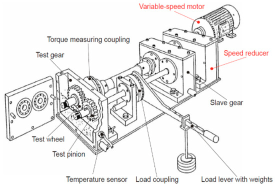
Figure 2.
Forschungsstelle fur Zahnrader und Getriebebau (FZG) mechanical power circulation gear test rig [5].
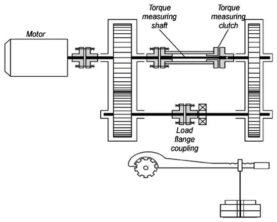
Figure 3.
Layout of the FZG gear test rig [4].
The closed-loop of the test rig is torsion loaded so that each of its sections, being in torsional equilibrium, has equal and opposite torques at its two ends. If the applied torque and the rotation at one end of a closed-loop section are in the same direction, then power will enter that section. If in the opposite direction at the other end, then power will leave the section. Since this applies to all loop sections, power will circulate continuously around the closed-loop in a direction that is determined by the combination of directions of torque and rotation [8]. Figure 4 shows the scheme of power flow with circulation in a closed-loop wherein PL_A and PL_B represent the power losses due to friction between the gears and the bearings inside the two gearboxes. From this scheme, it is evident that gearbox A has a heavier load than gearbox B.
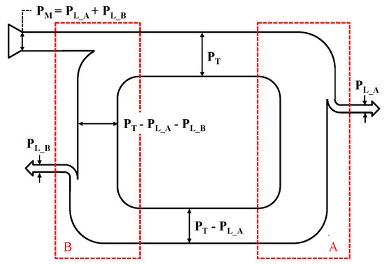
Figure 4.
Scheme of power flow in power circulation test rig.
This torque-applying clutch of the test rigs is simple and reliable, but it has a drawback; that is, the applied torque cannot be controlled during the test. Therefore, a variable torque test is impossible unless the test rig is terminated.
3. Design of the Mechanical Power Circulation Test Rig
3.1. Conceptual Design
The mechanical power circulation (or mechanical back-to-back type) rig has several gearboxes connected in a closed-loop to circulate the torque loads. It is composed of an electric motor, two auxiliary gearboxes (parallel gearboxes for torque circulation), a torque-applying device, lubrication systems, cooling systems, and control systems (Figure 5). The torque-applying device consists of a planetary gearbox and a hydraulic control system. With this device, the desired torque can be applied to the test gearbox. The torque is applied to the ring gear of the planetary gear train by a hydraulic control system that can be automatically controlled during the test. The applied torque results from the difference of the rotation direction and the rate of the sun and ring gears. The number of teeth of the gears is chosen such that, for a given rotation angle of the ring gear, the sun gears rotate in a different direction and at different angles, resulting in torque. Load is applied in the same manner as the planet carrier. The speed of the test gearbox is controlled by an electric motor, and the power supplied from the motor covers the frictional loss of the test rig. Figure 6 shows the scheme of power flow with circulation in a closed loop. In this figure, PL_SG, PL_MG, PL_AG1, PL_AG2, and PL_TAG represent the power losses due to friction between the gears and the bearings inside the three gearboxes and two test gearboxes. From this scheme, it is evident that the slave gearbox is more loaded than the master gearbox.
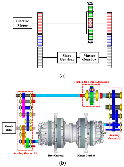
Figure 5.
Layout of the developed test rig. (a) Concept of the developed test rig (b) Configuration of the test developed rig.
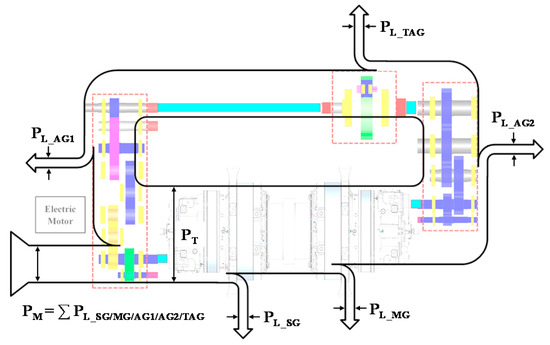
Figure 6.
Scheme of the power flow in the developed test rig.
The test rig was designed based on the size, capacity, and test requirements of the WTGBs. Figure 5 shows the conceptual design and layout of the apparatus, and Table 1 lists the specifications of the WTGBs that can be tested in the rig. In the case of a WTGB, the rotational speed of the high-speed shaft is usually 1100–2200 rpm and the rated rotational speed of an electric motor is 1180 rpm. Thus, gear ratios of the auxiliary gearboxes were selected such that all WTGBs of 5.8 MW or less could be tested. In the design of the mechanical power circulation test rig, if the slave and master gearboxes do not rotate at the same speed, additional torques will accumulate in the closed-loop, and the test rig could be damaged. Thus, this was considered for the gear ratio selection.

Table 1.
Specifications of gearboxes that can be tested.
A 3D model view and a photograph of the developed test rig are given in Appendix A.
3.2. Design of Gearboxes Used in the Test Rig
The gear ratios of auxiliary gearbox #1 (Figure 7), auxiliary gearbox #2 (Figure 8), and the torqued gearbox (Figure 9) were selected to meet the rated rotational speed required by the test WTGB. Furthermore, the optimal size of the entire gearbox was determined by considering the size of the test gearbox. When the rotation speed of the electric motor was 1000 rpm, auxiliary gearbox #1′s shafts ① and ② rotated at 1000 rpm and shaft ③ rotated at 2000 rpm. Auxiliary gearbox #2′s shaft ④ rotated at 285.714 rpm, shaft ⑤ rotated at 1000 rpm, and shaft ⑥ rotated at 2000 rpm. The torqued gearbox’s shaft ⑦ rotated at 1000 rpm and shaft ⑧ rotated at 285.714 rpm. Therefore, the design was made such that the test gearbox could be connected to shafts ② and ⑤ or shafts ③ and ⑥ of the auxiliary gearboxes according to the rotational speed of the high-speed shaft of the test gearbox.
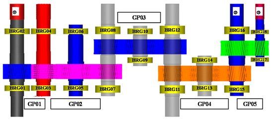
Figure 7.
Layout of auxiliary gearbox #1.
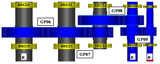
Figure 8.
Layout of auxiliary gearbox #2.
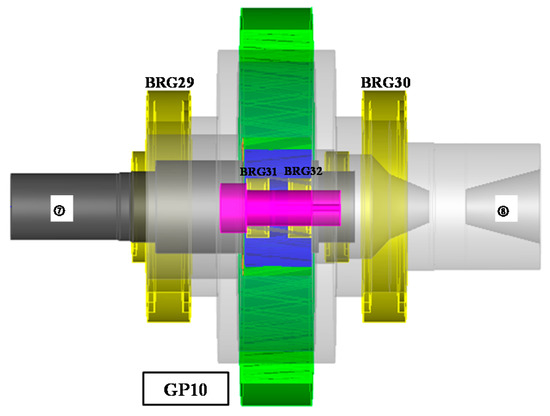
Figure 9.
Layout of torque application gearbox.
In the auxiliary gearbox design, if the number of gear pairs is small, the center distance of one gear pair will become too large, and the gear’s pitch line velocity, weight, and volume, balance, etc. may yield uncertainties. To address this, the number of gear pairs was increased. Shaft design and bearing selection were performed based on the designed gear pair. The torque application gearbox is a planetary geartrain with five planet gears. Based on the total size of the gearbox, the gear ratio was designed to be 3.5.
The ISO standard was used to assess the gear strength [9] and bearing life [10]. Detailed results are presented in Appendix B. In the results, gear pairs with the lowest safety factor were GP05 and GP09 of the auxiliary gearboxes (1.3212). The bearing with the shortest life was BRG32 of the torque application gearbox (30,683 h). The designed gear pairs and selected bearings satisfied the design criteria for a safety factor of at least 1.2 and a bearing life of 30,000 h, respectively. Therefore, the three gearboxes designed for the test rig were deemed suitable for testing WTGBs of 5.8 MW or less.
3.3. Hydraulic Control System Design for Torque-Applying Device
The section is based on previous research by Kim et al. [11].
The test rig applies torque in a closed-loop through a separate torque-applying device, which consists of a planetary gearbox and a hydraulic control system, as shown in Figure 10. The hydraulic control system consists of a controller, a directional control valve, two relief valves, four linear actuators, a hydraulic pump, an electric motor, and oil pressure lines. The directional control valve applies torque in the normal/reverse direction (A mode/B mode) to the torque arms of the planetary gearbox, by changing the direction of flow supplied from the hydraulic pump. A two-way valve is used. Two relief valves are installed between the directional control valve and hydraulic pump, which control the pressure of the entire hydraulic control system.
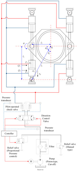
Figure 10.
Hydraulic circuit for controlling actuators [11].
The controller controls the movement of the four actuators by controlling the directional control valve, relief valve, and electric motor. It can switch between A and B modes by controlling the directional control valve and can vary the magnitude of the torque applied to the system by controlling the proportional pressure control-type relief valve. Furthermore, the electric motor can be stopped after the desired torque is applied to the torque-applying device, and the pressure of the actuators is maintained by the pilot-operated check valve. In this study, the switch control and on/off control were used to control a directional control valve and an electric motor, respectively. Additionally, a PID (Proportional Integral Derivative) controller was used to regulate a proportional pressure control-type relief valve. The parametric values of the PID controller were obtained by a trial-and-error method. Figure 11 shows a block diagram of the feedback control system to control the torque of the test rig. A controller input of 50.2 kN-m was set as the reference target torque, and the hydraulic actuators were operated until the target torque was reached using the feedback signal from a torque meter.
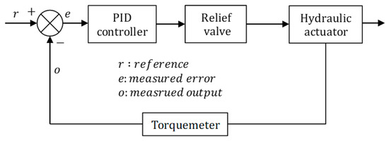
Figure 11.
Feedback control system for torque control.
Four actuators were used in the torque-applying device. If only two actuators were used (one each at the left and right lower sides of torque-applying device), the torque could not have been controlled accurately when applying it to the planetary gearbox due to the difference between the areas of the actuator rods arising from the same operating pressures of the actuators. Thus, radial loads other than the torque act on the planetary gearbox. However, if four actuators are used, torque can be controlled accurately when it is applied to the planetary gearbox because the actuators are operated at the same pressure. Thus, loads other than torque do not act on the planetary gearbox.
The ring gear torque, Tload, which is applied by the hydraulic control system, is expressed as the product of the input torque, Tin, of the sun gear and the gear ratio (i = Zr/Zs) of the planetary gearbox, and the force Fload acting on the actuator is calculated from radius l2 and safety factor s of the torque-applying device. The pressure required by the system can be derived from the force acting on the actuators and their cross-sectional areas. These relationships are expressed in Equations (1)–(5). The torque-applying device changes the linear motion, xp, of the actuator to rotational motion, θ. Therefore, there are mechanical limits to the torque-applying device. Equation (6) shows the rotational angle of the planetary gearbox depending on the change of stroke of the actuator.
The structure and specifications of the torque-applying device are shown in Figure 12 and Table 2, respectively.
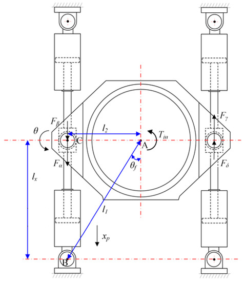
Figure 12.
Free-body diagram of the torque-applying device [11].
Table 2.
Specifications of the torque-applying device.
4. Experimental Analysis
4.1. Evaluation of Torque Range
The available torque range of the test rig was investigated through a series of tests. A torque meter was installed on the point connected to the high-speed shaft of the 5.8-MW gearbox shown in Figure 13, and a digital graduator was used to measure the rotational angle of ring gear of torque-applying device.
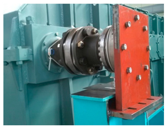
Figure 13.
Torque meter installed on the test rig.
The hydraulic system was operated, and the rotational angle was recorded until the torque of the high-speed shaft reached its maximum value (50.2 kN-m). The maximum rotational angle was 10.5° in all the 10 iterations of the test. This value is smaller than the angle of 23.8°, which is the rotational angle of the ring gear when the stroke of the hydraulic cylinder in the torque-applying device is the largest. Therefore, it can be concluded that the measurable torque range of the rig is enough to test 5.8-MW gearboxes.
After performing the preliminary test of the variable torque-applying device, the master/slave gearbox was mounted on the test rig to verify the performance of the torque-applying device while changing the torque according to the test conditions. Figure 14 shows the results of the test performed by changing the rotational speed of the motor and the torque of the torque-applying device according to the test conditions after applying the master/slave gearbox. Figure 14a,b present the measured rotational speeds of the output shaft of the master/slave gearbox, and Figure 14c,d show the torques of the output shaft of the master/slave gearbox. At the beginning of the rig verification test, the motor rotation speed was increased, and the torque of the torque-applying device was changed. At approximately 750 rpm, the rotational speed of the motor and the torque of the torque-applying device was changed to their target values. After 40 min of testing under the rated test conditions of the master/slave gearbox, the test rig was stopped while changing the torque and rotational speed. The test was not performed until the maximum torque (50.2 kN-m) of the test rig was reached due to the limitation of the rated condition of the master/slave gearbox. It was confirmed that, until the rated torque of 45.2 kN-m, there was no problem in performing the test while sequentially changing the torque of the torque-applying device.
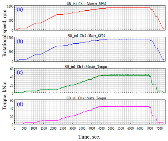
Figure 14.
Test result of rotational speed and torque change for the test rig validation.
4.2. Resonance Analysis
To confirm the occurrence of resonance in the developed test rig, a speed sweep test was conducted. After accelerometers were installed on the test gearbox of the test rig, the acceleration signals were measured as the rotational speed of the high-speed shaft was increased from 0 rpm to the maximum operating speed of 1100 rpm. Table 3 lists the specifications of the accelerometer and measurement equipment.
Table 3.
Specifications of measurement and analysis equipment.
The measured acceleration signals were used to analyze the frequency according to the rotational speed. Because the gear mesh frequencies of the first, second, and third stages of the test gearboxes under the maximum operational seed (1100 rpm) were 19 Hz, 122 Hz, and 513 Hz, respectively, the main acceleration component in the operating area was the gear mesh frequency, and no resonant frequency component appeared, as shown in Figure 15. That is, resonance did not occur in the operating region of the gearbox (0–1100 rpm). Thus, it was verified that the test rig had no problems when testing the gearbox.
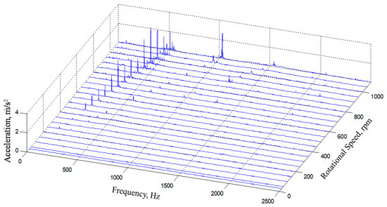
Figure 15.
Waterfall plot for vibration of the developed test rig.
5. Conclusions
In this study, a mechanical power circulation test rig was developed to test WTGBs of 5.8 MW or less. The rig consists of an electric motor, two auxiliary gearboxes, a torque-applying device, lubrication systems, cooling systems, and control systems. The torque-applying device consists of a simple planetary gearbox and hydraulic control system and applies torque to the test gearbox. The hydraulic control system consists of a controller, several valves, four linear actuators, a hydraulic pump, an electric motor, and oil pressure lines. It was designed to accurately control torque and eliminate the effect of loads other than the torque.
The torque-applying device was installed outside the test gearbox and developed to automate the controlling of applied torque. Therefore, compared with conventional mechanical power circulation test rigs, the developed test rig has the advantage of being able to apply variable torques in real-time during a test.
For auxiliary gearboxes, components such as bearings and gears were designed to have an adequate lifespan under the rated load condition of 5.8 MW. This was verified by comparing it with the ISO standard. Furthermore, the speed sweep test results confirmed the absence of resonance in the test gearbox in the operating region of 0–1100 rpm for the WTGB. Therefore, the developed test rig can be used to test performance indicators, such as efficiency, vibration, and noise, as well as durability and overload tests. Therefore, we believe that this rig can also be used in other large multi-MW gearboxes applied for power plants, ships, etc.
6. Patents
Geun-Ho Lee et al., (2011), KR Patent No. 10-1109540, Daejeon: Korean Intellectual Property Office.
Author Contributions
The co-author of this paper, Y.-J.P., contributed equally to the corresponding author. Conceptualization, G.-H.L. and Y.-J.P.; Methodology, G.-H.L. and Y.-J.P.; Software, J.-Y.O.; Validation, J.-G.K. and J.-S.N.; Formal Analysis, J.-Y.O.; Investigation, J.-S.N.; Resources, J.-Y.O.; Data Curation, J.-G.K.; Writing – Original Draft Preparation, G.-H.L. and Y.-J.P.; Writing—Review & Editing, J.-G.K.; Visualization, G.-H.L. and Y.-J.P.; Supervision, J.-G.K. All authors have read and agreed to the published version of the manuscript.
Funding
This research received no external funding.
Conflicts of Interest
The authors declare no conflict of interest.
Nomenclature
| i | Gear ratio of planetary gearbox (i = Zr/Zs) |
| Tin | Sun gear torque of planetary gearbox |
| Tload | Reaction torque of planetary gearbox |
| Fload | Force acting on actuator |
| s | Safety factor |
| dpiston | Piston diameter of actuator |
| drod | Rod diameter of actuator |
| PL_A(B) | Power loss due to friction of gears and bearings in gearbox A (B) |
| PL_SG(MG, AG1, AG2, TAG) | Power loss due to friction between gears and bearings in slave gearbox, master gearbox, auxiliary gearbox 1 and 2, and gearbox for torque application) |
| PM | Power supplied to closed loop in motor (sum of power losses of gearboxes A and B) |
| PT | Total power circulating in closed loop of test rig |
| Psystem | System pressure |
| l1 | Distance from center of planetary gearbox to connecting point of actuator |
| l2 | Distance from center of planetary gearbox to center of torque arm |
| Xp | Moving distance of actuator stroke |
| θf | Angle from vertical line of actuator to line AB |
| Fα | Force acting on actuator α |
| Fβ | Force acting on actuator β |
| θ | Rotation angle of planetary gearbox |
Appendix A

Figure A1.
3D model view of the developed test rig.

Figure A2.
Picture of the developed test rig.
Table A1.
List and description of test rig components.
Table A1.
List and description of test rig components.
| Index | Item | Description | No. of Items |
|---|---|---|---|
| 1 | Electric motor | 2.7 MW, 6P, 690 V, 60 Hz | 1 |
| 2 | Motor support | Rig support | 1 |
| 3 | Auxiliary gearbox #1 for torque circulation | Max. power: 5.8 MW | 1 |
| 4 | Auxiliary gearbox #1 support | Rig support | 1 |
| 5 | Torque meter & speed sensor #1 | up to 80 kN m, 3000 rpm | 1 |
| 6 | Bed plate | 2 m × 4 m: 6 pieces | 1 |
| 2 m × 5 m: 6 pieces | |||
| 7 | Slave gearbox | Gearbox for speed reduction | 1 |
| 8 | Torque arm support for slave gearbox | Rig support | 2 |
| 9 | Master gearbox | Gearbox for test | 1 |
| 10 | Torque arm support for master gearbox | Rig support | 2 |
| 11 | Torque meter & speed sensor #2 | up to 80 kN m, 2000 rpm | 1 |
| 12 | Auxiliary gearbox #2 for torque circulation | Max. power: 5.8 MW | 1 |
| 13 | Auxiliary gearbox #2 support | Rig support | 1 |
| 14 | Planetary gearbox for automatic torque application | Max. power: 5.8 MW | 1 |
| 15 | Hydraulic control system for automatic torque application | No. of cylinder: 4 Cylinders are connected to ring gear | 1 |
| 16 | Universal joint | - | 2 |
| 17 | Bearing block | - | 2 |
| 18 | Manual torque-applying device | Device for applying initial torque to closed-loop test rig | 1 |
| 19 | Bearing block support | - | 1 |
Appendix B
Table A2.
List and description of test rig components.
Table A2.
List and description of test rig components.
| Gear Pair Number | Safety Factor | |
|---|---|---|
| Root | Flank | |
| GP01 | 2.5138 | 1.4416 |
| GP02 | 1.7291 | 1.5737 |
| GP03 | 1.6789 | 1.5678 |
| GP04 | 1.7491 | 1.5978 |
| GP05 | 1.7614 | 1.3212 |
| GP06 | 2.5964 | 1.9290 |
| GP07 | 2.5291 | 1.5736 |
| GP08 | 3.5295 | 1.8712 |
| GP09 | 2.5163 | 1.3212 |
| GP10 | 3.0736 | 1.4849 |
| GP01 | 2.5138 | 1.4416 |
| GP02 | 1.7291 | 1.5737 |
| GP03 | 1.6789 | 1.5678 |
| GP04 | 1.7491 | 1.5978 |
| GP05 | 1.7614 | 1.3212 |
| GP06 | 2.5964 | 1.9290 |
| GP07 | 2.5291 | 1.5736 |
| GP08 | 3.5295 | 1.8712 |
| GP09 | 2.5163 | 1.3212 |
Table A3.
Life of bearings for test rig gearboxes.
Table A3.
Life of bearings for test rig gearboxes.
| Bearing Number | Life (h) | Bearing Number | Life (h) |
|---|---|---|---|
| BRG01 | >175,200 | BRG17 | 58,399 |
| BRG02 | >175,200 | BRG18 | 168,390 |
| BRG03 | >175,200 | BRG19 | >175,200 |
| BRG04 | >175,200 | BRG20 | >175,200 |
| BRG05 | 141,972 | BRG21 | >175,200 |
| BRG06 | >175,200 | BRG22 | >175,200 |
| BRG07 | 38,119 | BRG23 | >175,200 |
| BRG08 | >175,200 | BRG24 | >175,200 |
| BRG09 | 98,958 | BRG25 | 164,203 |
| BRG10 | >175,200 | BRG26 | 138,050 |
| BRG11 | >175,200 | BRG27 | 34,025 |
| BRG12 | 62,682 | BRG28 | >175,200 |
| BRG13 | >175,200 | BRG29 | >175,200 |
| BRG14 | 105,243 | BRG30 | >175,200 |
| BRG15 | 41,243 | BRG31 | 38,547 |
| BRG16 | >175,200 | BRG32 | 30,683 |
References
- Lloyd, G. Guideline for the Certification of Wind Turbine; GL: Hamburg, Germany, 2010. [Google Scholar]
- Spinato, F.; Tavner, P.; Bussel, G.; Koutoulakos, E. Reliability of wind turbine subassemblies. IET Renew. Power Gener. 2009, 3, 387–401. [Google Scholar] [CrossRef]
- Musial, W.; McNiff, B. Wind turbine testing in the NREL dynamometer test bed. In Proceedings of the AWEA’s WindPower 2000 Conference, Palm Springs, CA, USA, 2 May 2000. [Google Scholar]
- Mihailidis, A.; Nerantzis, I. A New System for Testing Gears under Variable Torque and Speed. Recent Patents Mech. Eng. 2009, 2, 179–192. [Google Scholar] [CrossRef]
- Arun, A.P.; Kumar, A.P.S.; Giriraj, B.; Rahaman, A.F. Gear Test Rig—A Review. Int. J. Mech. Mechatron. Eng. 2014, 14, 6–26. [Google Scholar]
- Jung, D.; Lee, Y.; Park, J. Reliability Evaluation of Torque Generator. J. Korean Soc. Power Syst. Eng. 2012, 16, 59–65. [Google Scholar]
- Krull, F.D. Wind turbine field and test rig testing as part of the design process for gearboxes: Test and validation requirements, Needs and Best Practices for Wind Turbine Gearboxes. Power Transm. Eng. 2014, 9, 44–49. [Google Scholar]
- Frost, R.B.; Cross, T.R. Full-load testing of large gearboxes using closed-loop power circulation. In Proceedings of the Fifth International Conference on Manufacturing Engineering, Wollongong, NSW, Australia, 11–13 July 1990. [Google Scholar]
- Calculation of Load Capacity of Spur and Helical Gears; ISO standards 6336-1,2,3,5,6; International Standardization Organization: Geneva, Switzerland, 2006.
- Rolling Bearings—Dynamic Load Ratings and Rating Life; ISO standards 281; International Standardization Organization: Geneva, Switzerland, 2007.
- Kim, J.-G.; Park, Y.-J.; Lee, G.-H.; Nam, Y.-Y.; Oh, J.-Y. Design of a Torque Application Device in Test Rig for a Wind Turbine Gearbox. Trans. Korean Soc. Mech. Eng. A 2015, 39, 507–515, (by permission of the Korean Society of Mechanical Engineers). [Google Scholar] [CrossRef]
© 2020 by the authors. Licensee MDPI, Basel, Switzerland. This article is an open access article distributed under the terms and conditions of the Creative Commons Attribution (CC BY) license (http://creativecommons.org/licenses/by/4.0/).