Article

Prediction of Sound Radiation from Submerged Cylindrical Shell Based on Dominant Modes

1
Acoustic Science and Technology Laboratory, Harbin Engineering University, Harbin 150001, China
2
Key Laboratory of Marine Information Acquisition and Security (Harbin Engineering University), Ministry of Industry and Information Technology, Harbin 150001, China
3
College of Underwater Acoustic Engineering, Harbin Engineering University, Harbin 150001, China
4
Indian Springs School, Indian Springs, Pelham, AL 35124, USA
*
Author to whom correspondence should be addressed.
Appl. Sci. 2020, 10(9), 3073; https://doi.org/10.3390/app10093073
Submission received: 21 March 2020 / Revised: 13 April 2020 / Accepted: 23 April 2020 / Published: 28 April 2020
(This article belongs to the Section Acoustics and Vibrations)

Abstract

:
A sound radiation calculation method by using dominant modes is proposed to predict the sound radiation from a cylindrical shell. This method can provide an effective way to quickly predict the sound radiation of the structure by using as few displacement monitoring points as possible on the structure surface. In this paper, modal analyses of a submerged cylindrical shell are carried out by taking the vibration mode of a cylindrical shell in a vacuum, as a set of orthogonal bases. The modal sound radiation efficiency and modal contributions to sound radiation power are presented, and comparison results show that a few modes dominantly contribute to the sound radiation power at low frequencies. These modes, called dominantly radiated structural modes in this paper, are applied to predict the sound radiation power of submerged cylindrical shells by obtaining the modal participant coefficients and sound radiation efficiency of these dominant modes. Aside from the orthogonal decomposition method, a method of solving displacement modal superposition equations is proposed to extract the modal participant coefficients, because few modes contribute to the vibration displacement near the resonant frequencies. Some simulations of cylindrical shells with different boundaries are conducted, and the number of measuring points required are examined. Results show that this method, based on dominant modes, can well predict the low-frequency sound radiation power of submerged cylindrical shells. In addition, compared with the boundary element method, this method can better reduce the number of required measuring points significantly. The data of these important modes can be saved, which can help to predict the low-frequency sound radiation of the same structure faster in the future.

1. Introduction

At present, underwater vehicles such as submarines and unmanned underwater vehicles (UUVs) are being widely used in national defense, marine development, and other fields. They are playing an increasingly important role in underwater attack, underwater defense, underwater detection, and underwater rescue. To evaluate their acoustic stealth performance and the influence of self-noise on the detection performance of local sonar, real-time and accurate prediction of radiated noise from underwater vehicles is increasingly needed. Therefore, predicting radiated noise from underwater structures has always been a concern of scholars [1,2,3,4]. Currently, the common method of predicting radiated sound from underwater structures is the prediction method using monitoring structure vibration. Another difficult problem for scholars is how to effectively reduce the number of measuring points used in the prediction and how to improve the efficiency of sound radiation prediction for the convenience of engineering applications.
The prediction of radiated sound from a vibrating structure is one of the important research fields in structural acoustics. Several classical and recognized calculation methods have been developed, such as the boundary element method (BEM) [1], the finite element method (FEM) [5], a method of combining BEM and FEM (FEM-BEM) [6,7,8] and the equivalent source method [9,10]. However, these conventional approaches have their own disadvantages. The FEM and the FEM-BEM methods require a known excitation force, which is often difficult to obtain in practical engineering applications. The BEM and the equivalent source method only need to know the surface vibration of structures, but they both require the vibration information of many measuring points on the structure surface. Insufficient measuring points are the key factors that restrict the prediction accuracy in practical applications. Moreover, the prediction efficiency of these two methods is low, due to the processing of many measuring points. Thus, many researchers have made other attempts to find a better way to predict the radiated sound field.
To improve the prediction efficiency, scholars have proposed some prediction methods based on acoustic radiation modes (ARM) [2]. In the course of carrying out research, Borgiotti [11] identified a set of orthonormal boundary velocity patterns through the singular value decomposition, viewed as the original idea of ARM [12,13]. To reduce the computational cost, many papers have proposed different and simpler algorithms to calculate ARM [14]. Some methods of applying ARM to the calculation of radiated sound power have been also proposed. Elliott and Johnson [15] obtained two formulations for calculating the radiated sound power based on the ARM and the structural mode, respectively, and they studied the number of sensors. Some new developments have been achieved in the application of ARM. Peters et al. [16] developed a modal decomposition technique to analyze the sound power contributed by the individual mode of a structure submerged in a heavy fluid. Haijun Wu et al. [17] proposed a new application for the ARM: computing the sound power of structures with convex shapes based on the mapped ARM and the mapping relationship. In general, the advantage of ARM is that it improves the prediction efficiency by applying the theory of modes. However, the eigenmode of structural vibration is a structural vibration mode, thereby making it inefficient at decomposing the structure vibration by using ARM. Moreover, no general calculation software currently exists for ARM. In this situation, the calculation of ARM of a general structure is cumbersome.
Researchers have also tried other approaches to solve the problem [18,19]. P. Ramachandrana and S. Narayanan [3] pointed out that statistical energy analysis (SEA) can be applied to predict the radiated sound power of a structure in the high-frequency band with high modal density. Given the theory of SEA [20], this method could only give a statistical answer, which always has obvious uncertainty, and it is only suitable for high frequencies. Hyeongill and Rajendra [21] described two analytical solutions based on the Rayleigh integral and based on BEM for the sound radiation of a thick annular disk with a free boundary. Zhang Qifan et al. [22] proposed an effective approach called acoustic transfer vector (ATV) to quickly evaluate the vibro-acoustic response by saving the ATV in advance in the database. The above methods are all based on establishing the integral relationship between the surface vibration velocity and the sound field to predict the radiated sound. Therefore, they all require a large number of measuring points on the structure surface. A. Tsouvalas and A.V. Metrikine [23] discussed a similar and complete approach for a fluid waveguide and dealt with more complicated situations. Apostolos Tsouvalas et al. [24] discussed the sound wave radiation from the perspective of the convergence of the solution in terms of the satisfaction of the kinematics at the shell-fluid interface, and also dealt with some complex situations.
To simplify the procedure of predicting the radiated sound field and efficiently obtain the radiated sound power of the structure, a new method based on the main radiation structural modes is proposed in this paper, and this method is developed from the modal contribution idea in the ARM method. Some numerical calculations indicated that when the underwater cylindrical shell vibrates at low frequencies, a certain structural mode called dominantly radiated structural mode (DRSM) contributes dominantly to the total radiated sound power in a certain frequency bands. On the basis of this characteristic, DRSM is used to efficiently predict the radiated sound power of underwater cylindrical shells. This method is efficient because it inherits the idea of efficient ARM and obtains the radiated sound power by superposition of several DRSMs. In addition, in most frequency bands, the DRSMs contribute significantly to the vibration displacement. Therefore, the solving displacement equations method can be used during modal decomposition, and will effectively reduce the number of required measuring points. Furthermore, structural modal information of the underwater structure can be precomputed and saved in the database for the next forecast and calculation, which makes it easier to meet the real-time requirements of online prediction.

2. Theory

2.1. Structural Mode

The structural modes are a set of orthogonal bases that describe the vibration of structures, and the modal participant coefficient represents the participant coefficient of each mode. The modes are the inherent properties of a structure, and they are related only to the structure itself and boundary conditions rather than the external excitation force. The displacement mode shape of each mode can be obtained by FEM.
According to basic vibration theory [24,25], when an elastic cylindrical shell is excited by steady-state external forces, and the boundary conditions of the shell structure are time-independent, the displacement field on the surface of the vibrating cylindrical shell can be obtained based on the principle of modal superposition as follows:
w = n , m W n m ϕ n m
where w is the displacement field on the surface of the vibrating structure, ϕ n m is the modal displacement of mode ( n , m ), the number n represents the circumferential wave numbers of the cylindrical shell, the number m represents the axial wave numbers of the cylindrical shell, and W n m is the modal participant coefficient of mode ( n , m ). The modal participant coefficients represent the participant degree of each mode when the cylindrical shell vibrates. The modal participant coefficients are related to the steady-state external excitation force. When a cylindrical shell is excited by the excitation forces with different types or at different positions, the participant coefficient of each order mode is different, which can lead to different vibration distribution of the cylindrical shell and finally result in a different radiated sound field distribution.

2.2. Calculation of Modal Participant Coefficients

The modal participant coefficient indicates the contribution of modal displacement to the total displacement of the structure [24]. A large modal participant coefficient corresponds to a great contribution. Two methods are used in this paper to calculate the participant coefficients of each mode. One method obtains the participant coefficients based on the characteristic of orthogonality between the modes and can be called the orthogonal decomposition method (ODM). The other method solves displacement equations, and is set up by the superposition of all modal displacements that contributed to the total vibration displacement; this method can be called the solving equations method (SEM).

2.2.1. Orthogonal Decomposition Method (ODM)

The structural modes of arbitrary model are orthogonal to each other, which means the surface integral of the product of the displacement distribution functions of any two modes is zero. This product also needs to be multiplied by a position-dependent weighting coefficient, which is the corresponding mass distribution function. For the convenience of analysis, all the cases in this paper are only under the circumstance of uniform thickness, which means that the weighting coefficient is constant in these cases. Furthermore, this constant can be incorporated into other integral constants without being considered separately.
According to the abovementioned principle of modal superposition, the displacement field of a vibrating structure can be expressed as Equation (1). Then, a new formula can be obtained by multiplying both sides of Equation (1) by modal displacement of ( p , q ) order mode and integrating the equation over the entire surface. According to the orthogonality between the modes, the new formula can be simplified. Finally, the symbols p and q can be replaced with symbols n and m after orthogonalization, and then the participant coefficient of ( n , m ) order mode is
W n m = s w ϕ n m d s s ϕ n m 2 d s

2.2.2. Solving Equations Method (SEM)

According to the basic idea that the displacement can be obtained by superposing the displacements of each order mode, the modal participant coefficient can be acquired by solving the displacement equations.
First, Q ( Q ≥ number of modes involved in the equation set) points on the surface of the vibrating structure is selected. The way to choose these points is subject to the principle of randomly and uniformly selecting points to avoid the correlation between the equations. The p order modal displacement can be represented as ϕ p , where p is from 1 to P , and the actual displacement of the vibrating structure can be represented as Φ , and the location of the measurement points can be represented as x q , where q is from 1 to Q ( Q P ), and p order modal participant coefficients will be expressed as W p . According to the principle of modal superposition, the displacement of a cylindrical shell can be expressed as the weighted superposition of modal displacements and then we can obtain some equations. The P modes involved in the equations all contribute largely to the actual vibration displacement of the cylindrical shell. If the actual vibration displacement and modal displacement are known, the equations can be solved and the modal participant coefficients can be obtained, as shown in Equation (3).
[ W 1 W 2 W p ] = [ ϕ 1 ( x 1 ) ϕ 2 ( x 1 ) ϕ P ( x 1 ) ϕ 1 ( x 2 ) ϕ 2 ( x 2 ) ϕ P ( x 2 ) ϕ 1 ( x Q ) ϕ 2 ( x Q ) ϕ P ( x Q ) ] 1 [ Φ ( x 1 ) Φ ( x 2 ) Φ ( x Q ) ]
The number of columns of the above participant coefficient matrix depends on the number of modes involved in the equation. If only a few modes have a large contribution to the actual displacement, the number of measuring points required in this method will be small. Then, the participant coefficient of these several modes can be easily solved. In the latter part of this article, this characteristic is used when solving the modal participant coefficients, which could effectively reduce the number of measuring points.

2.3. Calculation of Radiated Sound Power

When a structure vibrates in the air, its structural modes are orthogonal and also decoupled, which means that the modes do not affect each other. However, if the structure vibrates under water, then it will form an integrated system with the external water. Therefore, structural vibration is no longer independent, and its modes will be coupled with the water. The coupling characteristics between these modes are specifically reflected in the modal impedance [23,26].
According to the theory of modal superposition, the sound pressure on the surface of a cylindrical shell can also be described in the form of modal superposition as in Equation (1). Thus, sound pressure p can be expressed as
p = n , m P n m ϕ n m
where P n m is the modal participant coefficient of the sound pressure. P n m can be expressed as the product of the displacement modal coefficient and the modal impedance, like q W n q Z n m q . The component W n q is the modal participant coefficients of vibration displacement, Z n m q represents the contribution of mode ( n , q )’s vibration to mode ( n , m )’s sound pressure, called modal radiation impedance. Particularly, if q = m , then Z n m m will be called modal self-radiation impedance, and if q m , then Z n m q will be called modal mutual radiation impedance.
According to the definition of radiated sound power Π , it can be expressed as the surface integral of the normal sound intensity, which is related to the sound pressure and the normal vibration velocity. The formula can be represented as
Π = s 1 2 Re ( p ( j ω w ) * ) d s
where p is the sound pressure distribution function on the surface of cylindrical shells, j is the imaginary unit, w is the normal displacement distribution function on the surface of cylindrical shells, Re represents the real part of a complex, * represents the complex conjugate for scalars and complex conjugate transpose for vectors, and ω is the angular frequency.
When only the ( n , m ) order mode participates in the vibration of a cylindrical shell, as well as the participant coefficient of this mode is W n m , the displacement distribution will be W n m ϕ n m and the sound pressure on the surface in this situation can be described as W n m Z n m m ϕ n m . Then, according to Equation (5), the radiated sound power Π n m under the circumstance where the participant coefficient is W n m can be represented as
Π n m = s 1 2 Re ( W n m Z n m m ϕ n m ( j ω W n m ϕ n m ) * ) d s = 1 2 Re ( j ω ε n m | W n m | 2 Z n m m ) = | W n m | 2 Π ^ n m
where Π ^ n m = 1 2 Re ( j ω ε n m Z n m m ) , it represents the radiated sound power under the circumstance where the participant coefficient is 1. Equation (6) indicates that the radiated sound power under the circumstance where the participant coefficient is W n m is | W n m | 2 times that under the circumstance where the participant coefficient is 1.
When all modes participate in the vibration, on the basis of the theory of modal superposition, the displacement distribution becomes g , t W g t ϕ g t . As mentioned above, the sound pressure on the surface in this situation can be described as n , m q W n q Z n m q ϕ n m . The equations are integrated into Equation (5), and then the total radiated sound power can be presented as
Π = s 1 2 Re ( n , m q W n q Z n m q ϕ n m ( j ω g , t W g t ϕ g t ) * ) d s = n , m 1 2 Re ( j ω ε n m W n m * q W n q Z n m q )
In the low frequency range, modal coupling can be neglected, which does not influence the radiated sound power considerably [23,27]. If the mutual radiation impedance (off-diagonal case) is ignored, then Equation (7) can be simplified to
Π = n , m 1 2 Re ( j ω ε n m | W n m | 2 Z n m m ) = n , m Π n m
If the mutual radiation impedance is ignored, then the radiated sound power of a cylindrical shell can be expressed as the superposition of the radiated sound powers of each mode as shown in Equation (8).

3. Simulation Analysis of Vibration and Acoustic Radiation of Cylindrical Shell

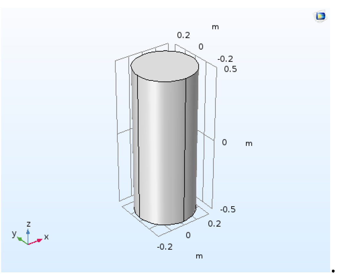
To analyze the relationship between modal radiated sound power and total sound power at low frequencies, a simulation of modal analysis and sound radiation analysis of a cylindrical shell with fixed ends is presented. The low frequency band mentioned in the article refers to the frequency band with the first few sound radiation peaks. The cylindrical shell model is shown in Figure 1. The length of the selected cylindrical shell model is 1 m, the radius is 0.2 m, and the thickness is 0.005 m. The material of the model is steel, with a density of 7800 kg/m3, a Young’s modulus of 2.06 × 10¹¹ pa, a Poisson’s ratio of 0.3, and a loss factor of 0.01. COMSOL Multiphysics (a commercial FEM software) is used to calculate the cylindrical shell’s modes, the mode, and the radiated sound power.

3.1. Structural Modes of Cylindrical Shell

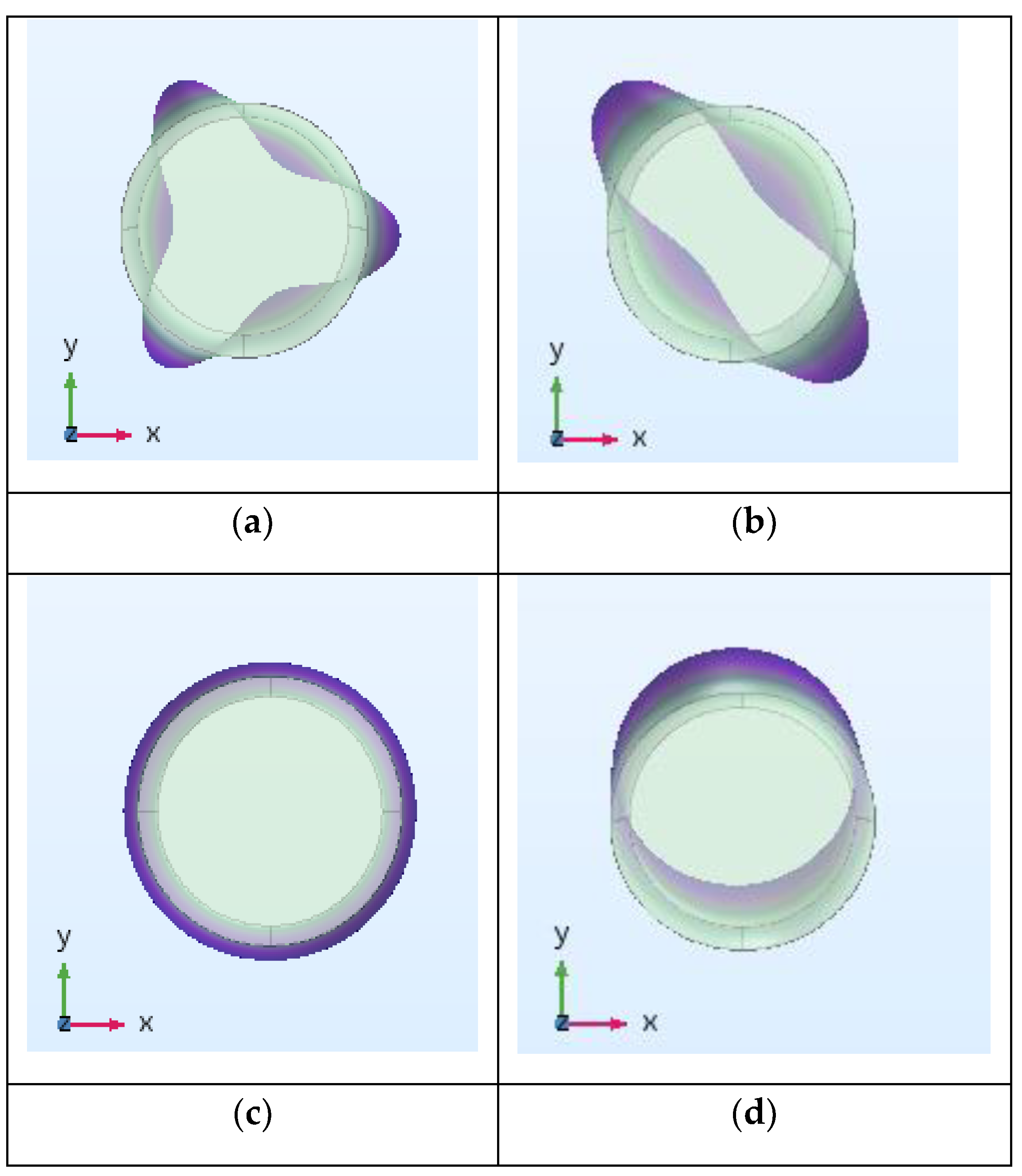
The modal analysis of the cylindrical shell with fixed ends can be performed by using COMSOL Multiphysics. Some modes are shown in Figure 2. They are the structural modes of the shell in vacuum and they are easier to obtain than the modes of the shell in the water. In this picture, a dark color corresponds to a large displacement. The frequencies in the title of Figure 2 are the modal natural frequencies. ( n , m ) are used to definite the mode order, where number n represents the circumferential wave numbers of the cylindrical shell, and number m represents the axial wave numbers of the cylindrical shell. Therefore, for cylindrical shells, the mode shape of a mode can be known from the n and m . Mode (0,1) is the breathing mode, mode (1,1) is the swing mode, and mode (2,1) is the squeezing mode. Compared with mode (3,1) and higher-order modes, the abovementioned modes have an obvious characteristic of overall vibration in a large area, which is why they may also have higher sound radiation efficiency and contribution of radiated sound power. These characteristics are proven in the later simulation analysis.

3.2. Sound Radiation Efficiency of Structural Modes

According to the theory of modal superposition, both the displacement of the cylindrical shell and the radiated sound field can be expressed in the form of modal superposition, as shown in Equations (1) and (4). To analyze the contribution of each structural mode to the radiated sound field, the sound radiation efficiency of each order mode needs to be analyzed.
According to the definition, radiated sound power w and mean square velocity < v 2 > are easily calculated. The sound radiation efficiency σ is related to radiated sound power w and mean square velocity < v 2 > [28].
After the modes of the cylindrical shell are acquired, velocity and radiated sound pressure can be simulated in COMSOL Multiphysics by taking the modal displacement as the boundary condition. Then, the radiated sound power and mean square velocity of the corresponding mode can be calculated. Finally, the radiated sound efficiency of each mode can be obtained.
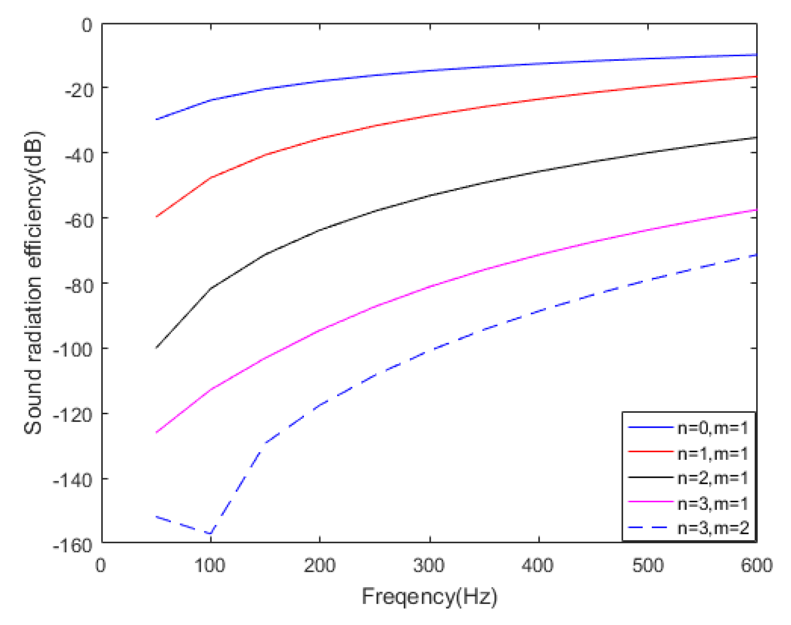
The sound radiation efficiency of several modes in this case is presented in Figure 3.
Figure 3 shows that the sound radiation efficiency of some modes is much higher than that of other modes, such as mode (0,1), mode (1,1), and mode (2,1). In addition, many calculations related to modal sound radiation efficiency show that the sound radiation efficiency of these modes is always the highest of all modes (in the low frequency band). The high sound radiation efficiency is due to the characteristic of overall vibration in a large area, as shown in Figure 2. These modes may contribute greatly to the total radiated sound power when the structure is vibrating and radiating energy outward; these modes are the focus in the latter part of this paper.

3.3. Sound Power Contributed by Structural Modes

For the abovementioned cylindrical shell, a normal excitation force of 1N is applied at a point in the middle of the cylindrical shell. In the whole frequency band, the excitation force does not change.
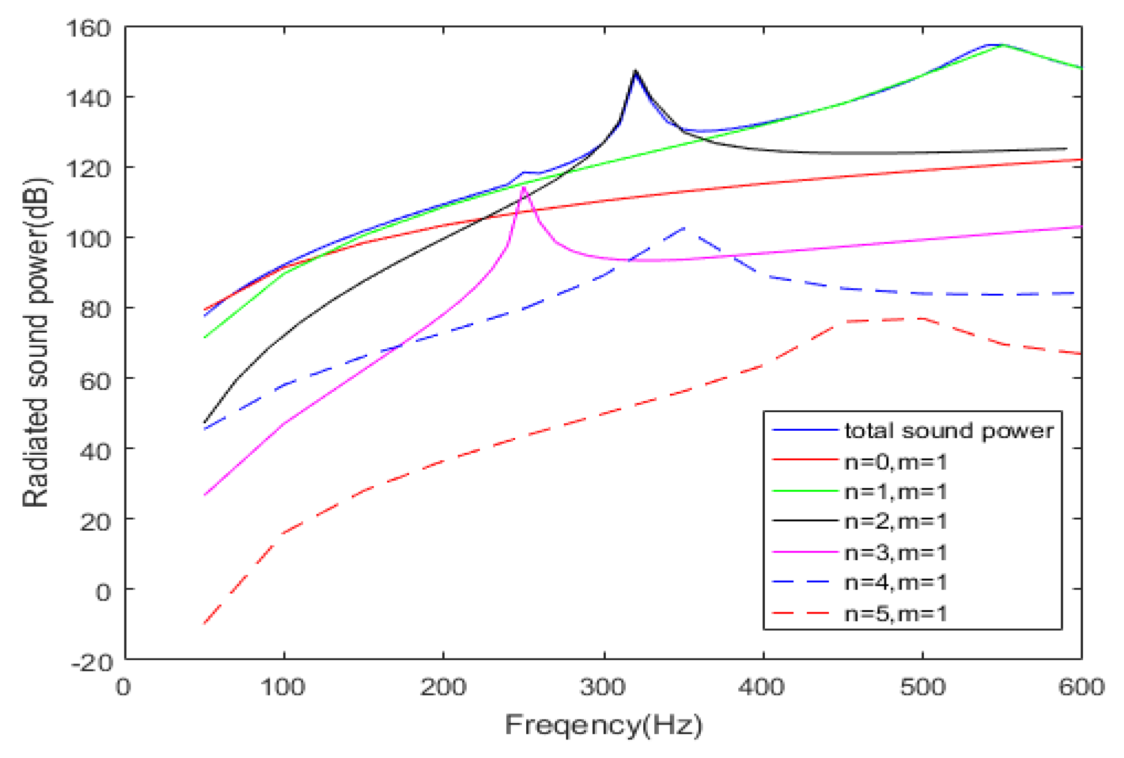
The vibration displacement distribution on the surface and the radiated sound power of the cylindrical shell were calculated by using FEM software. According to the orthogonal decomposition method mentioned in Section 2.2.1, the participant coefficient of each mode can be acquired by decomposing the vibration displacement on the surface. A detail that should be pointed out is that these modal participant coefficients are frequency-dependent. Then, according to Equation (6), the radiated sound power under the circumstance where the participant coefficient is W n m can be easily obtained from that under the circumstance where the participant coefficient is 1, as calculated by FEM. The results are compared with the total radiated sound power of the cylindrical shell, as shown in Figure 4.
As can be seen from Figure 4, the radiated sound power contributed by mode (3,1), mode (2,1), mode (0,1) and mode (1,1) are nearly equal to the total radiated sound power of the cylindrical shell in the corresponding frequency bands. These modes can be called DRSMs. For example, mode (0,1) is the DRSM in the frequency band below 100 Hz, mode (3,1) is the DRSM in the frequency band near the sound radiation peak at about 250 Hz, mode (2,1) is the DRSM in the frequency band near the sound radiation peak at about 310 Hz and mode (1,1) is the DRSM in the frequency band near the sound radiation peak at about 540 Hz. Moreover, this mode has a very high sound radiation contribution in the entire low frequency band, so it should be calculated over the entire band. Figure 4 also shows that the contribution of other modes to the total radiated sound power is much smaller, such as mode (4,1) and mode (5,1). Significantly, the sound radiation efficiency of these DRSMs is also very high, as shown in Figure 3, thus providing a method to preliminarily determine the DRSMs, because the high-efficiency modes are more likely to become the DRSM.
A comparison among the radiated sound power of each mode with the total radiated sound power of the cylindrical shell indicates that the sound power of several DRSMs is the main component of the total sound power at low frequencies. This characteristic prompts a new direction of sound radiation prediction. That is, as long as the radiated sound power of these DRSMs can be predicted, the total radiated sound power can be easily derived from them—this approach is the sound radiation prediction method based on the DRSMs proposed in this paper. The key to the prediction is to identify the DRSMs and obtain their participant coefficients.

3.4. Analysis of Displacement Contribution from DRSMs

The previous analysis shows that the key problem of the sound radiation prediction method based on the DRSMs is to identify the DRSMs and obtain their modal participant coefficients. The identification of the DRSMs can be realized by trial calculation in the finite element simulation and the analysis of the contribution of the structural modes to the total radiated sound power. The participant coefficients of the DRSMs can be obtained by modal decomposition based on the vibration displacement distribution of the cylindrical shell. Therefore, a reasonable modal decomposition method needs to be chosen when analyzing the contribution of each mode to the total vibration displacement.
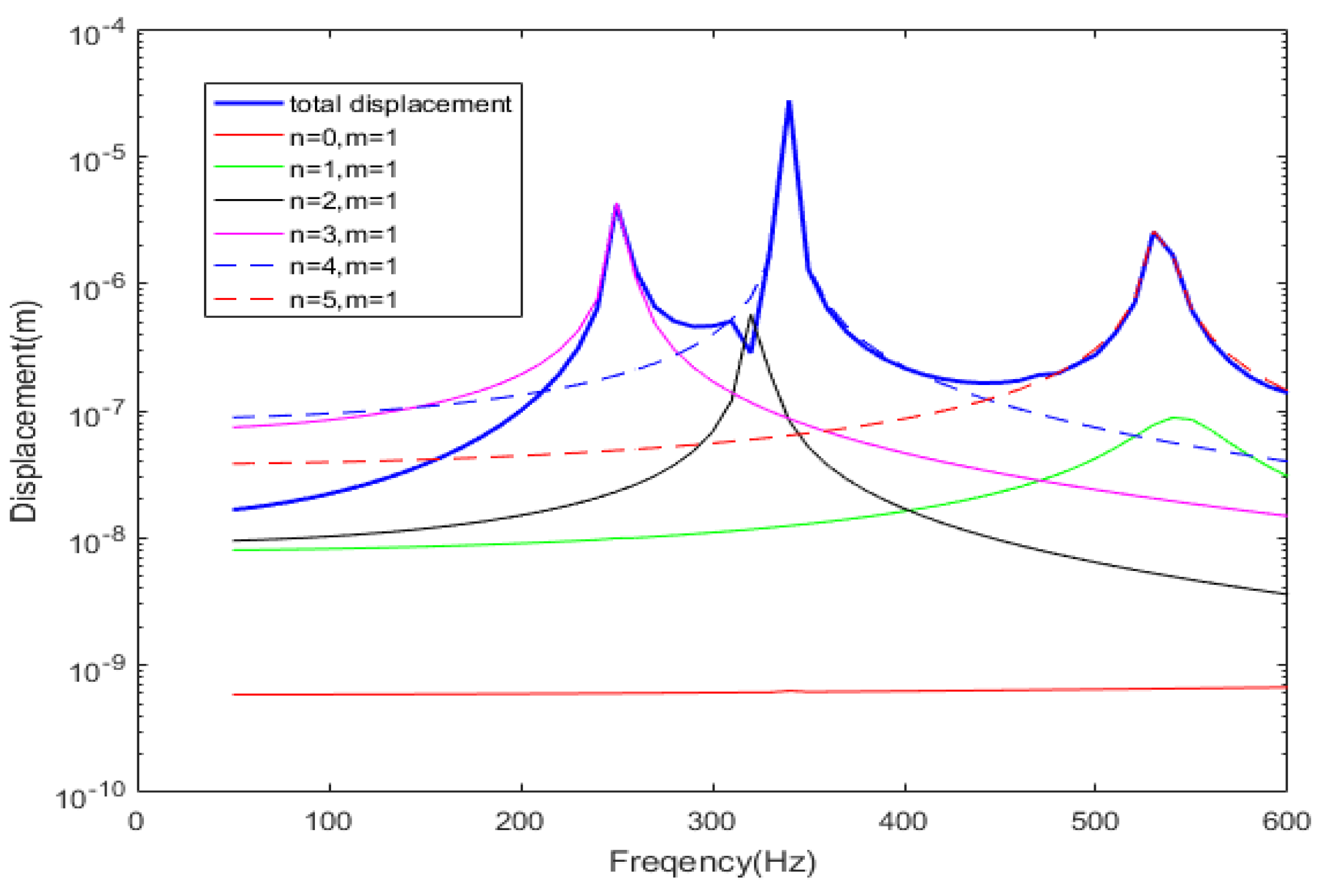
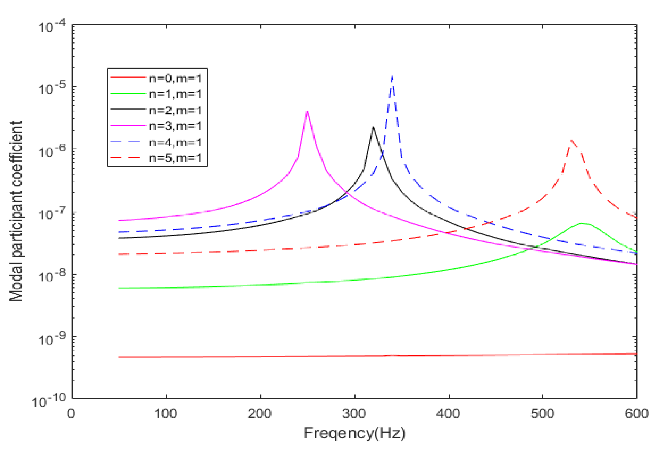
For the previous cylindrical shell model, the modal displacement contributed by several modes at a certain point of the cylindrical shell are easily calculated and compared with the total displacement, as shown in Figure 5. Figure 6 shows the comparison of different modal participant coefficients in this case. Figure 5 and Figure 6 show that although the mode (0,1) is the DRSM in the frequency band below 100 Hz, the contribution of this mode to the total displacement of the cylindrical shell is very small and much less than that of partial modes with a large contribution, which means that the extraction of modal participant coefficients will be difficult. In the frequency band near 250 Hz, mode (3,1) is the DRSM and the main component of the vibration displacement of the cylindrical shell. In the frequency band near 320 Hz, mode (2,1) is the DRSM. For the vibration, several other modes contribute significantly to the total displacement, but the displacement contribution of the mode (2,1) still has the same level of contribution as these few other modes. Moreover, a similar situation exists in the frequency band near 550 Hz. Therefore, the acquisition of the modal participant coefficients must fully consider the differences in the contribution of the DRSMs to the total vibration displacement in the corresponding frequency band.

4. Prediction of Radiated Sound Power based on the DRSMs

To verify the correctness of this prediction method based on the DRSMs, another excitation point was randomly selected on the same cylindrical shell again. Then, sound radiation prediction was performed without knowing the position of the excitation point and the magnitude of the excitation force; only the displacement of some measuring points on the surface of the cylindrical shell is known. Moreover, according to the previous trial calculation, the DRSMs in each frequency band are also known.

4.1. Prediction of Low-Frequency Sound Radiation

According to the conclusions mentioned in Section 3.4, the modal participant coefficient of the DRSM (0,1) is very small, and many other structural modes have a major contribution to the vibration of the structure. To use the solving equations method to calculate the modal participant coefficients in this case, the mode shapes of too many modes need to be known, and the displacement equations will involve too many modes. Moreover, for numerical calculation methods such as FEM, the mode shapes of higher-order modes are difficult to calculate accurately. Therefore, the abovementioned orthogonal decomposition method can be used to obtain the modal participant coefficient of the DRSM (0,1); this method only needs to know the modal displacement function of this mode.
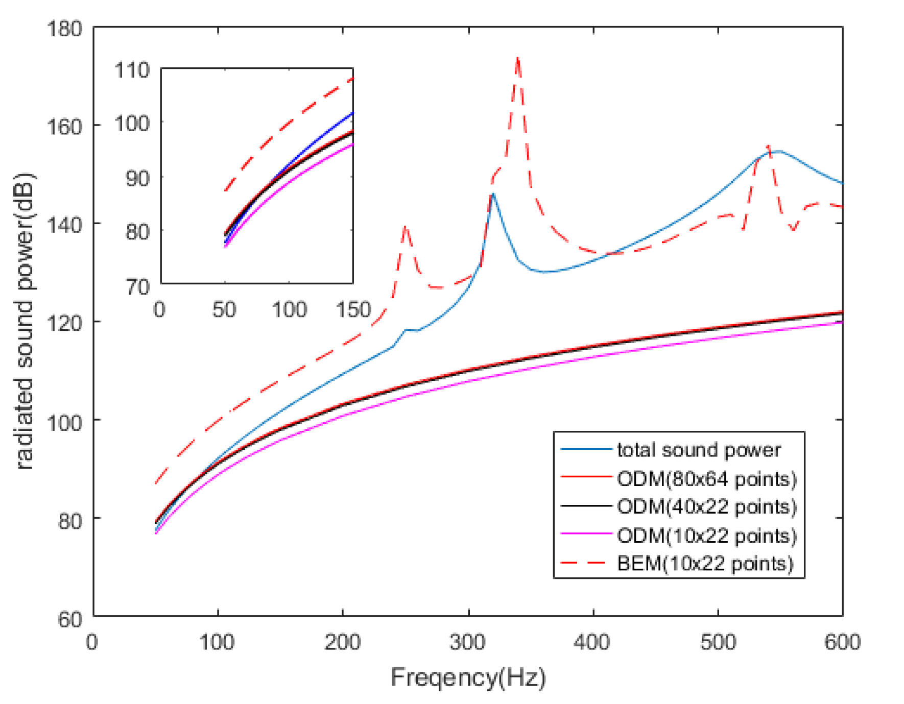
For the new prediction, the orthogonal decomposition method (ODM) is used to acquire the participant coefficient of the DRSM (0,1) according to Equation (2). Then, the number of measuring points required for acquiring the precise participant coefficient of the DRSM (0,1) is analyzed. This method includes integration on the surface of the cylindrical shell, which is why the measuring points should be uniformly selected on the surface. Three schemes of measuring points, namely, 80 × 64 (80 points are evenly distributed on the circumference with the same axial coordinate; 64 points are evenly distributed on the generatrix with the same circumferential coordinate), 40 × 22, and 10 × 22, are respectively used to calculate the modal participant coefficient and predict the radiated sound power of the cylindrical shell in the low frequency band. The prediction results are compared with the total radiated sound power calculated by the FEM, as shown in Figure 7. The screenshot in the upper-left corner of Figure 7 shows that the former two schemes have better prediction effects under 100 Hz, while the third scheme (10 × 22) has slightly worse prediction results, whose prediction error is less than 3 dB in the frequency band from 50 Hz to 100 Hz. With the vibration displacement data of these 10 × 22 measuring points used as boundary conditions, the BEM was used to predict the radiated sound power, as shown in Figure 7. The prediction error of the BEM is almost 8 dB, which means that the prediction method based on the DRSMs can effectively reduce the number of measuring points.

4.2. Prediction of Sound Radiation near the Sound Radiation Peak

According to the conclusions mentioned in Section 3.4, in the frequency band near the sound radiation peak, the modal participant coefficients of the corresponding DRSMs are larger than that of some other modes. Therefore, only a few modes, including the DRSMs, have a major contribution to the vibration of the structure. The solving equations method can be used to calculate the mode participant coefficients, which need only the mode shapes of several important modes. Obtaining the participant coefficients is easier by using this method than by using the orthogonal decomposition method.
For the previous cylindrical shell example, several modes with larger displacement contributions to the vibration of the structure, including the DRSMs, are selected, and the displacement equations are set up according to the principle of the solving equations method. The equations are solved to obtain the modal participant coefficients of the DRSMs according to Equation (3), and then the corresponding radiated sound power is calculated. The selection of measuring points on the surface of the cylindrical shell should be as random as possible to reduce the correlation between the displacement equations.
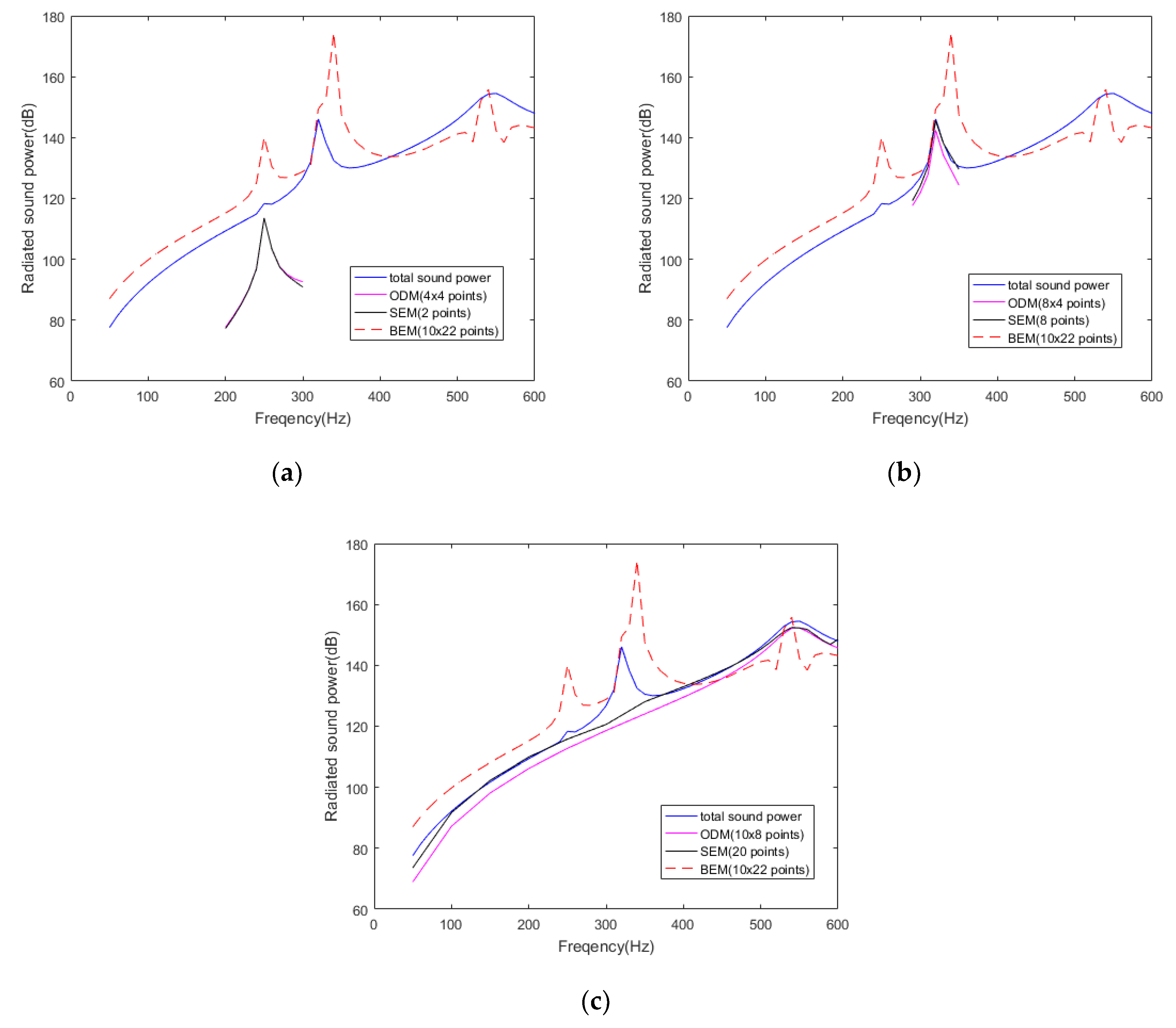
In Figure 8, for the solving equations method (SEM), the DRSM (3,1) requires only two measuring points to calculate an almost accurate result for radiated sound power, the DRSM (2,1) requires only eight measuring points, and the DRSM (1,1) requires only 20 measuring points. The radiated sound power of each DRSM is calculated and compared with the total radiated sound power in their corresponding frequency band, as shown in Figure 8. Using only a few measuring points can also obtain good prediction results. As a comparison, Figure 8 also shows the prediction results obtained by using the orthogonal decomposition method (ODM). The DRSM (3,1) requires 4 × 4 measuring points, the DRSM (2,1) requires 8 × 4 measuring points, and the DRSM (1,1) requires 10 × 8 measuring points. If the number of measuring points is reduced, then the result will be worse. This finding means that the solving equations method can effectively reduce the number of measuring points, compared with the orthogonal decomposition method. These modes should only be used to predict the radiated sound power in the corresponding frequency band, because they are not the DRSM in other frequency bands, and the prediction result may have errors. As a comparison, Figure 8 also gives the prediction results obtained by using the BEM. The vibration displacement data of 10 × 22 measuring points is used as boundary conditions to calculate the radiated sound field. This result shows that the two other methods need much fewer measuring points than the BEM.

4.3. Prediction of Sound Radiation over the Entire Frequency Band

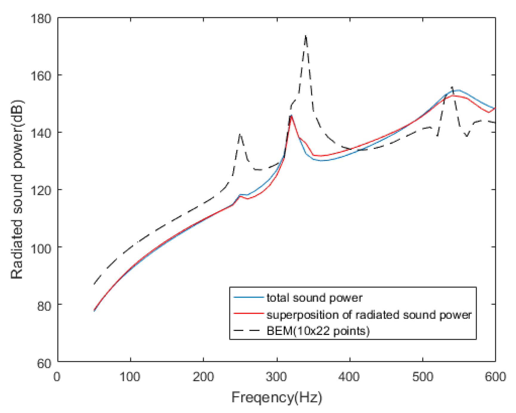
According to Equation (12), the total radiated sound power of the cylindrical shell can be approximately calculated by superposing the radiated sound power of the DRSMs. The radiated sound power of each DRSM was obtained previously, and they are superimposed to obtain the final prediction result of the total radiated sound power. The prediction result is compared with the actual radiated sound power of the same model calculated by the FEM, as shown in Figure 9. The radiation prediction of the DRSM (0,1) uses 220 (10 × 22) measuring points, the DRSM (3,1) uses two measuring points, the DRSM (2,1) uses eight measuring points, and the DRSM (1,1) uses 20 measuring points. The prediction curve of the radiated sound power is in good agreement with the actual curve. In Figure 9, compared with the traditional BEM, the DRSM method can effectively reduce the number of required measuring points.

4.4. Other Examples

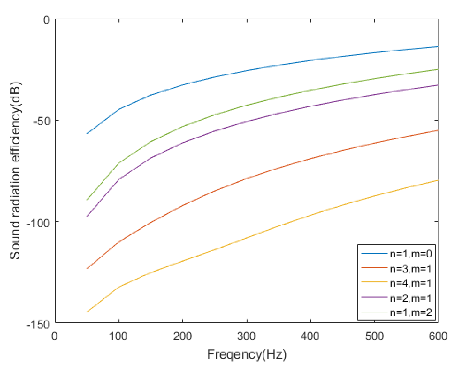
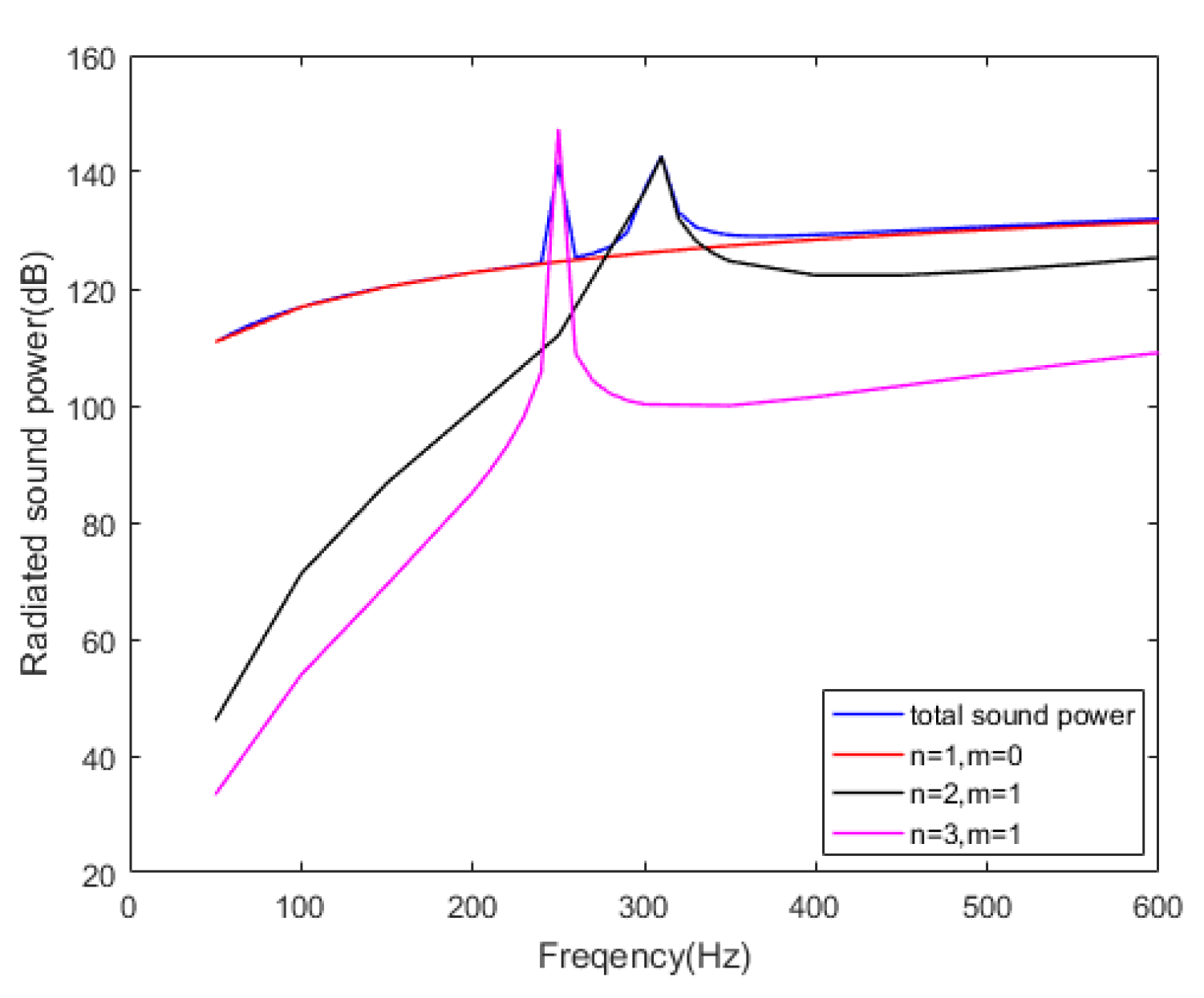
As we know, the inherent modes of the same model with different boundary conditions are different. For the cylindrical shell model described above, the fixed boundary at both ends was changed to a free boundary. The analysis of the DRSMs was performed in the same way, and the prediction result of the free model was examined. First, the sound radiation efficiency of each mode was calculated, as shown in Figure 10. Unlike the fixed cylindrical shell, the mode with the highest sound radiation efficiency is the mode (1,0), which is a translational mode and the lowest-order mode of the free cylindrical shell. Through precalculation, the contribution of each mode to the total radiated sound power is analyzed, as presented in Figure 11. The DRSMs in the low frequency band were found, including mode (1,0), mode (2,1), and mode (3,1).
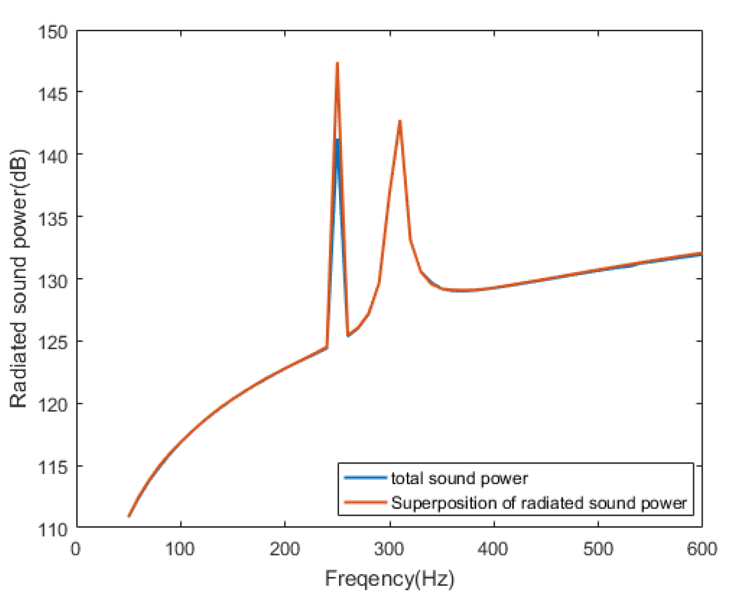
Then, for the cylindrical shell with free ends, the vibration displacement and radiated sound power of the cylindrical shell were recalculated after the position of the excitation point was changed. On the basis of the vibration displacement data, the prediction result of the radiated sound power from the mode (1,0) uses 220 (10 × 22) measuring points, the mode (3,1) uses eight measuring points, and the mode (2,1) uses random 20 measuring points. The prediction result is compared with the reference radiated sound power curve of the same model directly calculated by the FEM, as shown in Figure 12. The DRSM method can acquire a good prediction result.
For a cylindrical shell with mass rings at both ends, DRSM-based sound radiation prediction was also performed. The length of the cylindrical shell model is 1 m, the radius is 0.25 m, and the thickness is 0.005 m. The material of the model is steel, and its structural material parameters are the same as those of the previous cylindrical shell. Mass rings with a thickness of 0.05 m and a width of 0.605 m are located at both ends of this cylindrical shell, both sides of the model are free, and an excited point is added on the surface. The cylindrical shell model with mass rings is shown in Figure 13.
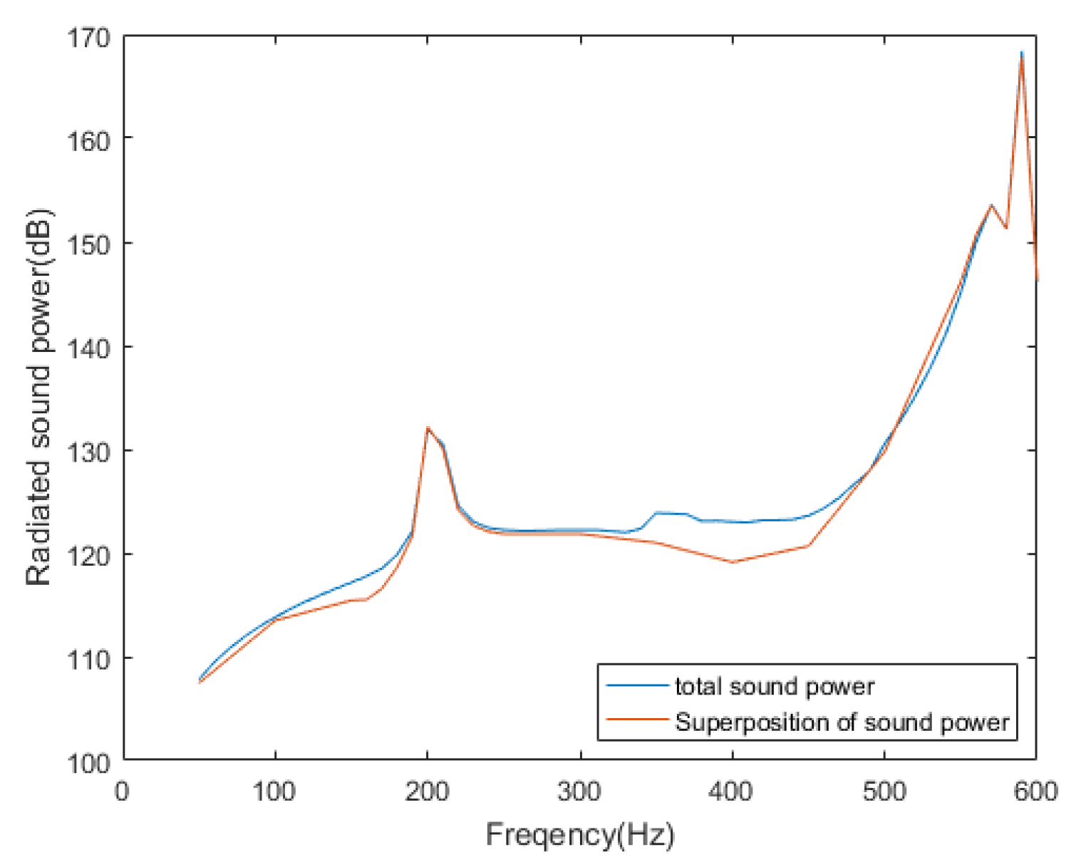
The DRSM method is used to predict the radiated sound field. The final prediction results are shown in Figure 14. The forecast curve is in good agreement with the actual curve directly calculated by the FEM.

5. Conclusions

A new method based on the DRSMs is proposed for the underwater sound radiation of a cylindrical shell. When the cylindrical shell vibrates at low frequencies, some DRSMs exist in the corresponding frequency bands. The radiated sound power of these DRSMs can be superposed to obtain the prediction results of the total sound power. The modal decomposition can use two different methods, both of which reduce the number of measuring points. Through the modal analysis of a fixed cylindrical shell, the DRSMs exist and contribute largely to the sound radiation in their frequency band, and high-efficiency modes are more likely to become the DRSM. A further study on the modal decomposition of the same cylindrical shell shows that different DRSMs can apply different methods—the orthogonal decomposition method or the solving equations method—to solve modal coefficients, which depends on the modal participant degree in the vibration displacement. These two methods show their superiority to the BEM in terms of the number of measuring points. Moreover, the cases of the free cylindrical shell and the cylindrical shell with mass rings demonstrate the correctness and the quickness of this new prediction method. This method can efficiently lower the requirement on the number of measuring points, which is beneficial to engineering applications. Furthermore, structural modal information of the underwater structure can be precomputed and saved in the database for the next forecast, which makes it easier to meet the real-time requirements of online prediction.
When this method is used to predict the radiated sound power by superposing the sound power of the DRSMs, the mutual coupling between each order is ignored at low frequencies. This assumption is valid, because the circumferential modal coupling of the cylindrical shell is relatively weak. For other models, such as flat plate, where the mutual coupling between modes cannot be ignored, the modal coupling effect needs to be considered during modal superposition. Otherwise, it will cause a large prediction error.
Author Contributions

All authors have read and agreed to the published version of the manuscript. Conceptualization, C.Z. and D.S.; Data curation, S.L.; Formal analysis, C.Z. and S.L.; Funding acquisition, C.Z. and D.S.; Investigation, S.L.; Methodology, C.Z. and S.L.; Project administration, D.S.; Resources, D.S.; Software, C.Z. and S.L.; Supervision, C.Z. and D.S.; Validation, C.Z., S.L., Y.H. and Y.S.; Visualization, S.L., Y.H. and Y.S.; Writing—original draft, S.L.; Writing—review & editing, C.Z.

Funding

This research was funded by the Stable Supporting Fund of Acoustic Science and Technology Laboratory (Grant No. JCKYS2019604SSJS009) and National Natural Science Foundation of China (Grant No. 11974089).

Conflicts of Interest

The authors declare no conflict of interest.

References

  1. Copley, L.G. Integral equation method for radiation from vibrating bodies. J. Acoust. Soc. Am. 1967, 41, 807–816. [Google Scholar] [CrossRef]
  2. Cunefare, K.A. The Design Sensitivity and Control of Acoustic Power Radiated by Three-Dimensional Structures. Ph.D. Thesis, The Pennsylvania State University, State College, PA, USA, 1990. [Google Scholar]
  3. Ramachandrana, P.; Narayananb, S. Evaluation of modal density, radiation efficiency and acoustic response of longitudinally stiffened cylindrical shell. J. Sound Vib. 2007, 304, 154–174. [Google Scholar] [CrossRef]
  4. Kwon, H.W.; Hong, S.Y.; Song, J.H. Energy flow models for underwater radiation noise prediction in medium-to-high-frequency ranges. J. Eng. Marit. Environ. 2016, 230, 404–416. [Google Scholar] [CrossRef]
  5. He, Z.C.; Liu, G.R.; Zhong, Z.H. An edge-based smoothed finite element method (ES-FEM) for analyzing vibro-acoustic analysis. Comput. Methods Appl. Mech. 2009, 199, 20–33. [Google Scholar] [CrossRef]
  6. Peters, H.; Kessissoglou, N.; Marburg, S. Modal decomposition of exterior acoustic-structure interaction problems with model order reduction. J. Acoust. Soc. Am. 2014, 135, 2706–2717. [Google Scholar] [CrossRef]
  7. Tong, Z.; Zhang, Y.; Zhang, Z. Dynamic behavior and sound transmission analysis of a fluid structure coupled system using the direct-BEM/FEM. J. Sound Vib. 2009, 299, 645–655. [Google Scholar] [CrossRef]
  8. Ding, Y.M.; Wang, H. FEM-BEM analysis of tyre-pavement noise on porous asphalt surfaces with different textures. Int. J. Pavement Eng. 2017, 20, 1090–1097. [Google Scholar] [CrossRef]
  9. Koopmann, G.H.; Song, L.; Fahnline, J.B. A method for computing acoustic fields based on the principle of wave superposition. J. Acoust. Soc. Am. 1989, 86, 2433–2438. [Google Scholar] [CrossRef]
  10. Huang, H.; Zou, M.S.; Jiang, L.W. Study on the integrated calculation method of fluid–structure interaction vibration, acoustic radiation, and propagation from an elastic spherical shell in ocean acoustic environments. Ocean Eng. 2019, 177, 29–39. [Google Scholar] [CrossRef]
  11. Borgiotti, G.V. The power radiated by a vibrating body in an acoustic fluid and its determination from boundary measurements. J. Acoust. Soc. Am. 1990, 88, 1884–1893. [Google Scholar] [CrossRef]
  12. Arenas, J.P. Numerical computation of the sound radiation from a planar baffled vibrating surface. J. Acoust. Soc. Am. 2008, 16, 321–341. [Google Scholar] [CrossRef]
  13. Peters, H.; Kessissoglou, N.; Marburg, S. Enforcing reciprocity in numerical analysis of acoustic radiation modes and sound power evaluation. J. Comput. Acoust. 2012, 20, 1250005. [Google Scholar] [CrossRef]
  14. Photiadis, D.M. The relationship of singular value decomposition to wave-vector filtering in sound radiation problems. J. Acoust. Soc. Am. 1990, 88, 1152–1159. [Google Scholar] [CrossRef]
  15. Elliott, S.J.; Johnson, M.E. Radiation modes and the active control of sound power. J. Acoust. Soc. Am. 1993, 94, 2194–2204. [Google Scholar] [CrossRef]
  16. Peters, H.; Kessissoglou, N.; Marburg, S. Modal decomposition of exterior acoustic-structure interaction. J. Acoust. Soc. Am. 2013, 133, 2668–2677. [Google Scholar] [CrossRef] [PubMed]
  17. Wu, H.J.; Jiang, W.K.; Zhang, Y.L. A method to compute the radiated sound power based on mapped acoustic radiation modes. J. Acoust. Soc. Am. 2013, 135, 679–692. [Google Scholar] [CrossRef]
  18. Yi, Y.; Brian, R.M.; Michael, J.K. Vibroacoustic analysis of periodic structures using a wave and finite element method. J. Sound Vib. 2019, 457, 333–353. [Google Scholar]
  19. Zou, M.S.; Liu, S.X.; Qi, L.B. An analytical formulation for the underwater acoustic radiation of a cylindrical shell with an internal flexural floor based on the reciprocity theorem. Appl. Acoust. 2019, 154, 18–27. [Google Scholar] [CrossRef]
  20. Zhang, B.; Xiang, Y.; He, P.; Zhang, G.J. Study on prediction methods and characteristics of ship underwater radiated noise within full frequency. Ocean Eng. 2019, 174, 61–70. [Google Scholar] [CrossRef]
  21. Hyeongill, L.; Rajendra, S. Comparison of two analytical methods used to calculate sound radiation from radial vibration modes of a thick annular disk. J. Sound Vib. 2005, 285, 1210–1216. [Google Scholar]
  22. Zhang, Q.F.; Li, W.; Wang, C.Z. The Fast Prediction of Sound Radiation from Typical Submarine Cabin based on Acoustic Transfer Vector. In Proceedings of the 2016 IEEE/OES China Ocean Acoustics (COA) IEEE, Harbin, China, 9–11 January 2016. [Google Scholar]
  23. Tsouvalas, A.; Metrikine, A.V. A semi-analytical model for the prediction of underwater noise from offshore pile driving. J. Sound Vib. 2013, 332, 3232–3257. [Google Scholar] [CrossRef]
  24. Tsouvalas, A.; Dalen, K.N.; Metrikine, A.V. The significance of the evanescent spectrum in structure-waveguide interaction problems. J. Acoust. Soc. Am. 2015, 138, 2574–2588. [Google Scholar] [CrossRef] [PubMed] [Green Version]
  25. Laulagnet, B.; Guyader, J.L. Modal analysis of a shell’s acoustic radiation in light and heavy fluids. J. Sound Vib. 1989, 131, 397–415. [Google Scholar] [CrossRef]
  26. Peter, R.S. Modal coupling in the vibration of fluid-loaded cylindrical shell. J. Acoust. Soc. Am. 1982, 71, 813–823. [Google Scholar]
  27. Sandman, B.E. Fluid-loading influence coefficients for a finite cylindrical shell. J. Acoust. Soc. Am. 1976, 60, 1256. [Google Scholar] [CrossRef]
  28. Cunefare, K.A. The minimum multimodal radiation efficiency of baffled finite beams. J. Acoust. Soc. Am. 1991, 90, 2521–2529. [Google Scholar] [CrossRef]
Figure 1. Cylindrical shell model with fixed ends.
Applsci 10 03073 g001
Figure 2. Partial low-order modes. (a) mode (3,1): 397.88 Hz, (b) mode (2,1): 553.18 Hz, (c) mode (1,1): 1029.9 Hz, (d) mode (0,1): 1593.7 Hz.
Applsci 10 03073 g002
Figure 3. Modal sound radiation efficiency curves of different order modes.
Applsci 10 03073 g003
Figure 4. Radiated sound power curves of different order modes.
Applsci 10 03073 g004
Figure 5. Comparison between the total displacement of a midpoint on the cylindrical shell and the modal displacements of different order modes.
Applsci 10 03073 g005
Figure 6. Modal participant coefficients of different order modes.
Applsci 10 03073 g006
Figure 7. Comparison of the radiated sound power calculated by different prediction methods and comparison of the radiated sound power calculated by the same method with different number of measuring points.
Applsci 10 03073 g007
Figure 8. Comparison of the radiated sound power calculated by different methods and the number of measuring points required by different methods (a) dominantly radiated structural mode (DRSM) (3,1), (b) DRSM (2,1), (c) DRSM (1,1).
Applsci 10 03073 g008
Figure 9. Comparison of the superposed curve of the radiated sound power from the DRSMs, the prediction curve of the boundary element method (BEM), and the reference prediction results.
Applsci 10 03073 g009
Figure 10. Modal sound radiation efficiency of different order modes.
Applsci 10 03073 g010
Figure 11. Radiated sound power of several order modes.
Applsci 10 03073 g011
Figure 12. Comparison between superposed curve of the radiated sound power from the DRSMs and the reference prediction result.
Applsci 10 03073 g012
Figure 13. Cylindrical shell model with mass rings.
Applsci 10 03073 g013
Figure 14. Comparison between the superposed curve of the radiated sound power from the DRSMs and the reference prediction result.
Applsci 10 03073 g014