Featured Application
In the paper, we further propose two novel concepts called Pre Idle Transitions (PIT) and Pre Idle Places (PIP) for the IMFFP-2. Once PIT or PIP is identified from a deadlock Petri nets model, one can bypass all PIP under the process of solving MFFP, and the computational time can hence be shortened.
Abstract
In industry 4.0, all kinds of intelligent workstations are designed for use in manufacturing industries. Among them, flexible manufacturing systems (FMSs) use smart robots to achieve their production capacity under the condition of a high degree of resources sharing. As a result, deadlock states usually appear unexpectedly. For solving the damage deadlock problem, many pioneers have proposed new policies. However, it is very difficult to make systems maximally permissive even if their policies can solve the deadlock problem of FMSs. According to our survey, the Maximal number of Forbidding First Bad Marking (FBM) Problems (MFFP) seems to be the best technology to obtain systems’ maximally permissive states in the existing literature. More importantly, the number of added control places (CP) is the smallest among the existing research works. However, when the complexity of a flexible manufacturing system increases, the computational burden rises rapidly. To reduce computational cost, we define a new concept named Pre Idle Places (PIP) to enhance the computational efficiency in Seeking Liveness-Enforcing Supervisors. We can bypass all PIP once they can be identified from a deadlock system under the process of solving MFFP. According to the data showed in three classical examples, our proposed Improved MFFP is better than conventional MFFP in terms of computational efficiency with the same controllers.
1. Introduction
Since flexible manufacturing systems (FMSs) use smart robots to achieve their production capacity under the condition of a high degree of resources sharing, deadlock states usually appear unexpectedly. For solving the deadlock problems of FMSs, many pioneers have focused on this issue [1,2,3,4,5,6,7,8,9,10,11,12,13,14,15,16].
Generally, three kinds of technologies are proposed to solve the deadlock problems of FMSs: deadlock avoidance, deadlock detection and recovery, and deadlock prevention [7]. Firstly, deadlock avoidance is adopted to prevent an FMS from reaching any deadlock state. Although it has a higher efficiency, it always fails to eliminate all deadlock states. The deadlock detection and recovery approach allows existing deadlock states to be reachable. Once deadlock occurs, the system detects and reallocates resources for recovery. Finally, deadlock prevention is proposed to prevent a deadlock situation from being reached. It is important to note that deadlock prevention does not need any run-time cost, since it solves the deadlock of FMSs in the design and planning stages.
In the deadlock prevention domain, two main analysis methods are designed to solve FMS deadlock problems: structural and reachability graph analysis, respectively. The former utilizes some structural items, such as all kinds of siphons [6,13,14,17,18,19,20,21,22,23,24,25,26,27]. Some generated siphons are found in uncontrolled models, which may become unmarked or partially marked. A siphon denotes a general set of places. In the case of a deadlock, the siphon cannot regain any new marking from the original ones, i.e., all transitions in this model are disabled, and a deadlock is recognized. To prevent a deadlock state from being reached, no places in these siphons may be empty. The objective is reached by designing and adding a control subnet to the model with its initial marking. Huang et al. [13] develop a formalized and iterative approach with two main stages. These two stages are required in each iteration in order to create new siphons after attaching them to the FMS model. Li and Zhou [18] propose a method with a much smaller control subnet than in previous works, with the same results. Huang et al. [14] introduce an iterative method, adopting two kinds of control places: ordinary and weighted control places. They attempt to prevent siphons from losing their tokens and guarantee more permissive systems. However, structural analysis seems suboptimal and leads to low utilization rates of system resources, although it does lower computational cost.
Reachability graph analysis [28,29,30,31,32,33,34,35,36,37] requires the enumeration of all generated markings. The set of these markings is hence referred to as the reachability graph (RG). The RG includes all reachable markings, which can be classified as one of two parts: the live zone (LZ) and deadlock zone (DZ). The DZ contains deadlock markings and critical bad markings, which inevitably lead to deadlock zones. The LZ contains all live markings and is also recognized as a deadlock-free-zone (DFZ). The objective is to forbid all markings in the DZ and to make sure all markings in the LZ are still reachable. According to the characteristics of RG and system complexity, marking explosion problems may occur during the computation of reachability graph analysis, implying that the increase of FMS model size leads to a corresponding increase in computational cost. Uzam [28] develops a deadlock prevention policy based on a theory of regions that proves maximal liveness performance. However, the policy fails to determine all sets of event-state separation problems (ESSPs), and its application seems limited to certain special nets only. Therefore, some works [34,35,36,37] aim to develop a more computationally efficient optimal deadlock control policy based on the theory of regions. Uzam and Zhou [5] propose a reduction technique to simplify large FMS models. To reduce computation, first-met bad markings (FBMs) are adopted in these works. FBMs are the set of markings in the DZ and the first entrance from the LZ to the DZ. However, as indicated by [38], this process requires the repeated calculation of reachability graphs.
Pirrodi et al. [39] consider selective siphons to reduce redundancy problems and provide small-size controllers. The control policy solves the deadlock problems of FMSs successfully. It also makes FMSs optimal. However, as indicated by [40], the process of eliminating all critical markings is time-consuming, since all legal markings must be checked in each iterative step. According to the above descriptions, it is clear that determining how to obtain optimal (maximally permissive) controllers for solving the FMS deadlock problem seems an extremely time-consuming and difficult issue. Therefore, in [33] Pan et al. also propose a policy called the enhancement of selective siphon control method to improve the efficiency of deadlock prevention in FMSs.
For improving the above disadvantage, Chen et al. [1] brought forward a new concept named MFFP (i.e., the Maximal number of Forbidding First Bad Marking (FBM) Problems) to obtain maximally permissive reachable markings with a much smaller number of controllers based on the reachability graph analysis method and Place Invariant (PI) [41]. It successfully solves the problem of the excessive consumption of time. However, when the complexity of a flexible manufacturing system increases, the computational burden rises rapidly. Besides, in our survey the MFFP could only be applied in certain special nets, and outside S3PR [6], the method would fail. Therefore, in our previous paper [42], we proposed an iterative method called IMFFP-1 to solve the disadvantage of [1] so that it can be used in all general cases whether the controlled net is optimal or suboptimal. Subsequently, for reducing computational time, in [43] we proposed two novel concepts called Pre Idle Transitions (PIT) and Pre Idle Places (PIP). However, the proposed definitions seemed rough and immature.
Therefore, in this paper, we aim to redefine and give the formal definitions of PIT and PIP. Please note that we can bypass all PIP once they can be identified from a deadlock flexible manufacturing system under the process of solving MFFP. From the resulting data based on three classical examples, the further improved MFFP (called IMFFP-2) method seems to achieve a better computational efficiency with the same controllers. Please note that in this paper we focus on enhancement of computational efficiency for the conventional MFFP. Therefore, in this paper we consider the same kind of Petri Net (PN) class as that in [1,2]. On the other hand, some deadlock preventions that can recover all reachable markings using transition-based controllers [44,45,46,47,48,49] and inhibitor arcs [50] are also proposed. In the future, we will follow the work in [51] to discuss a divide-and-conquer-method and try to enhance their computational efficiency.
2. Preliminaries
2.1. Petri Nets (PNs)
A Petri Net [52], also called a Place/Transition Net, is a four-tuple N = (P, T, F, W). Both P and T are non-empty sets. Generally, P is a finite set of places, and T is a finite set of transitions, disjointed to each other. The set is the arcs of this net, which is represented by one-way arrows from its nodes to denote a flow relation in a PN model. The mapping assigns a weight to an arc: if , and otherwise; where and is the set of non-negative integers. We call the postset of , and is called the preset of x. A marking is a multi-set of its places, which allocates tokens to each place of PNM. We denote as the number of tokens in place . The pair is called a marked Petri net or a net system. A net is pure if implying that . The incidence matrix of the pure net is a integer matrix with .
A transition is enabled at marking if , which is denoted as . Once an enabled transition fires, it generates a new marking , denoted as , where . The set represents all markings reachable from by firing any possible sequence of transitions. The set is the reachable markings of net with initial marking , often denoted as . It can be graphically indicated by a reachability graph, which can, in turn, be denoted as . It is a directed graph in which each node represents a marking in , and arcs are labeled by the fired transitions.
Let be a net system with . A transition is live at if . The pair is live if , is live at . It is dead at if .
A P-vector is a column vector indexed by . P-vector is called a P-invariant (place invariant, PI for short) if and . P-invariant is said to be a P-semiflow if . Let be a PI of and be a reachable marking from . Then, .
2.2. Identify All FBMs
In the Reachability Graph (RG) method, all reachable markings in the initial reachability graph analysis can be divided into two main groups: illegal and legal markings [35]. Illegal markings include deadlock and quasi-deadlock markings. The set of deadlock markings is defined as follows:
Definition 1
[35]. The set of deadlock markings = {M∈ R(N, M0)| at M; no transition can be enabled}.
The quasi-deadlock markings are defined as follows:
Definition 2
[35]. The set of quasi-deadlock markings = {M∈R(N, M0)| M must eventually evolve into a dead one regardless of transition firing sequences}.
The reachable markings, not including quasi-deadlock and deadlock markings, are called legal markings. The set of legal markings is the maximal number of reachable markings of a system, from which the initial marking is reachable without leaving . Further, the set of legal markings can be defined as follows:
Definition 3.
.
The of Definition 3 signifies the set of illegal markings. Therefore, the set of illegal markings can be defined as:
Definition 4.
.
Definition 4 means that all dead and quasi-dead markings can also be viewed as the set of illegal markings. Further, can be reached directly from any legal marking in an RG of a PNM. Please note that the first-met illegal marking is the same as the first-met bad marking (FBM) [1]. In our opinion, the first-met illegal marking (FIM) seems to be superior to the FBM. Therefore, the definition of first-met illegal marking (FIM) is presented formally as follows:
Definition 5.
.
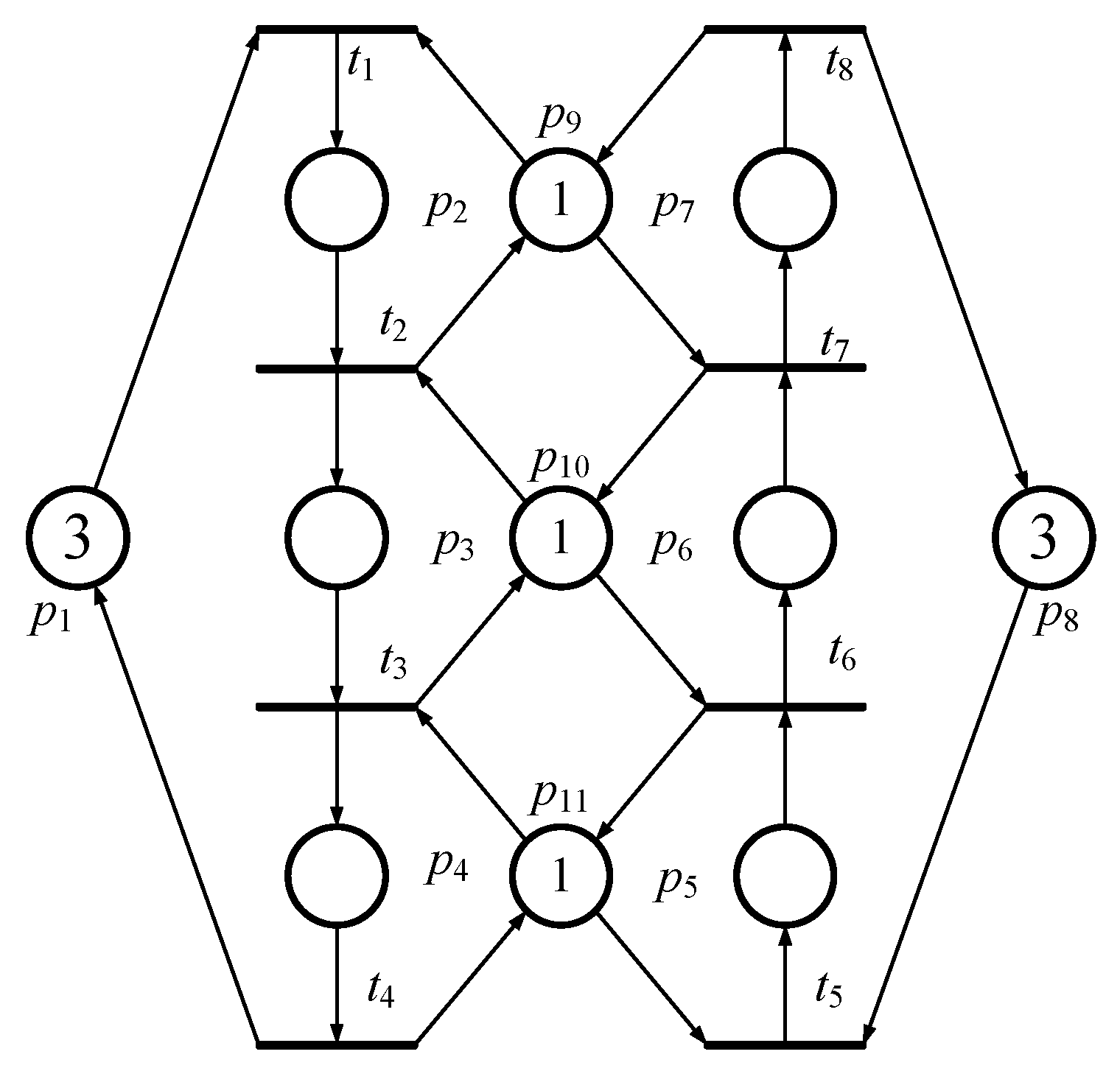
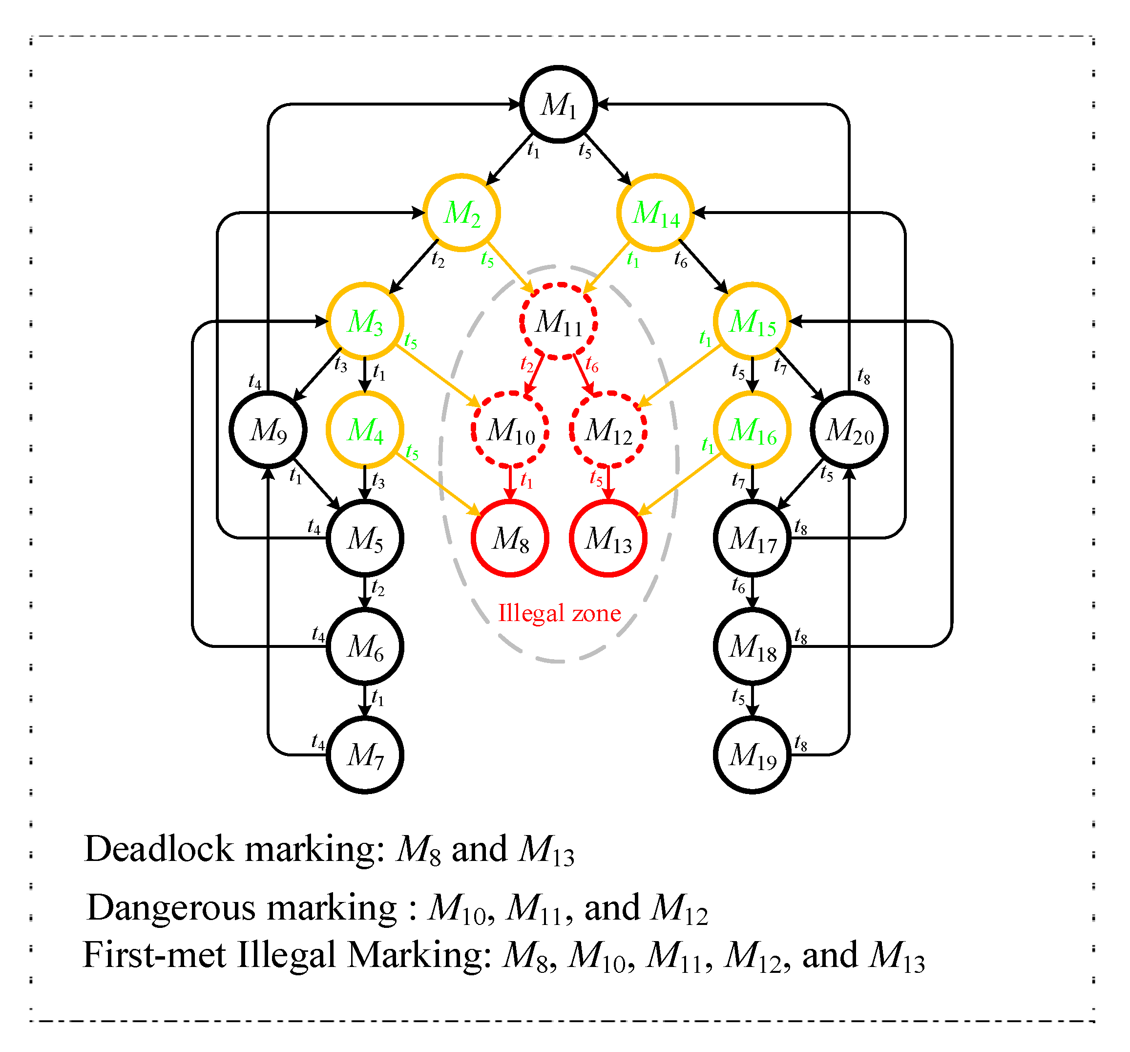
According to an example, one can understand the easily. Referring to Figure 1, the PNM has two idle places (i.e., p1 and p8, both with three tokens in them), six operation places (p2~p6), and three resource places (p9~p11, all with one token in them). Figure 2 is its reachability graph. In Figure 2, there are 20 reachable markings in total. Further, according to Definitions 1~4, there are 15 and 5 (i.e., 2 and 3 ) in Figure 2. In this example, all (i.e., deadlock marking M8, quasi-deadlock marking M10, quasi-deadlock marking M11, quasi-deadlock marking M12 and deadlock marking M13) are FIMs since they all fit Definition 5.
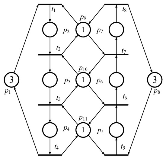
Figure 1.
A simple flexible manufacturing system (FMS) model based on Petri Net (PN) theory.
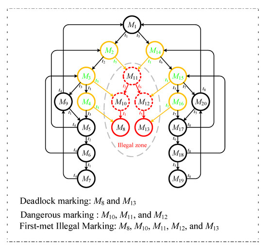
Figure 2.
The reachability graph of Figure 1.
In the following section, an improved deadlock prevention policy with an enhancement of computational efficiency is proposed. In this deadlock policy, just a few FBMs need to be identified. Once the few FBMs in the reachability graph are forbidden, the system is deadlock-free. In other words, under the same number of controllers, the efficiency of our algorithm is better than the MFFP method [1]. The detailed information of the proposed policy is presented as follows.
3. Improved Policy with Enhancement of Computational Efficiency
In this section, we will present our improved policy and further try to redefine and give the formal definitions of PIT, PIP and Crucial Vector Covering Approach for enhancing the computational efficiency of the conventional MFFP.
3.1. Finding Controllers from Place Invariant (PI) Concept
According to the definitions in [5,8], three types of places are given for FBM based on PN theory, including Idle places , Resource places , and Activity places , respectively. The initial marking of a reachability graph of a PNM is denoted as . The activity places must be considered among all kinds of places in using the PI concept [41].
Therefore, the PI concept is the most important factor and will help in designing maximally permissive controllers in this section. In [3], Yamalidou et al. first proposed the PI concept as follows:
where both and are non-negative integers, and denotes the number of tokens in place . Furthermore, for calculating the controllers of a system, more non-negative integers are given and the new equality is as follows:
By using Equation (2) every time, one can obtain control places so that some illegal markings can be removed until the FMS becomes deadlock-free. However, it could simultaneously eliminate some legal markings. Therefore, Chen et al. [1,11] propose a novel concept called MFFP to improve the above PI control method to hold the maximally permissive live legal markings.
3.2. MFFP
By identifying a few useful FBMs based on conventional PI control concepts, Chen et al. [1,11] proposed a novel PI control method, MFFP, to identify all maximally permissive controllers (i.e., control places). Accordingly, there are two kinds of algorithms based on the MFFP presented in their papers [1,11]. However, according to our study, the two algorithms seem logically identical. Therefore, in this paper, we select the first type of MFFP algorithm as the object to improve and enhance its computational efficiency. In this paper, we still call the two kinds of algorithms MFFP.
In [1], for obtaining maximally permissive PI controllers, there are two constraints used to design the Integer Linear Programming Problem (ILPP). In other words, once the optimal PI controllers are added into the original system, all FBMs can then be excluded from all legal markings. This system becomes live and keeps the maximally permissive (or optimal) markings since just FBMs are forbidden. In addition, only activity places need to be considered since the ILPP belongs to PI control. Therefore, based on Equation (1), a set is further used to redefine Equation (1) as follows.
In Equation (3), it is considered that each FIM can be forbidden by every relative controller added to the deadlock system. can be replaced by and variable can be redefined in Equation (4):
Following Equation (4), variable must smaller than since is true. Accordingly, one new constraint can be given as follows:
On the other hand, for holding all legal markings, the calculation is as follows:
By using Equations (5) and (6), the optimal PI controller developed by Chen et al. [1,12] can then be obtained.
3.3. Crucial Vector Covering Approach
Under the process of calculating all PI controllers, the computational cost is very high if all the reachable markings need to be considered. Computational cost and computer time could be reduced once crucial legal markings and FBMs can be identified. Based on the above reason, a Crucial Vector Covering Approach (CVCA) is proposed and defined in this subsection. Firstly, the conventional Vector Covering Approach (VCA) is introduced as follows:
Definition 6
[1]. Let there be any two markings Ma and Mb in . The marking Ma covers Mb if Ma Mb , which is denoted as Ma Mb.
Theorem 1
[1]. Let Ma and Mb be any two markings in with Ma Mb. If Mb is forbidden by one PI, Ma will be also forbidden. On the contrary, if Ma is not forbidden by a PI, Mb will not be forbidden either.
Please note that Definition 6 seems imprecise according to our experimental results. For example (please refer to Figure 2), and are any two markings, with and , respectively. For comparison, the detailed information of all reachable markings in Figure 2 is presented in Table 1.

Table 1.
The properties of all reachable markings in Figure 2.
Accordingly, is checked. Therefore, according to Definition 6, must be covered by since . In addition, according to Theorem 1, if is forbidden by the PI controller, must be also forbidden. However, in fact, is not forbidden in the situation that is forbidden. Therefore, we revise Definition 6 so that it can be accurate and can fit Theorem 1. The new definition is presented as follows:
Definition 7.
.Let Ma and Mb be any two markings in. The marking Ma is said to cover Mb ifMaMbMaMb, which is denoted as
Please note that we add the extra condition Ma Mb in Definition 7. Further, ( = so it can be precise and fit Theorem 1. Accordingly, we use Definition 7 instead of Definition 6 in this paper.
We also provide an example so that the readers can follow (please also refer to Figure 1 and Figure 2). The markings M6 and M7 are any two markings in the reachability graph of Figure 1. Further, their properties are and , respectively. The number of idle places in is equal to 2 and is equal to 3. Then, . It is worth noting that ⊇ since and ( = Surely, . We check if Definition 7 fits Theorem 1 by using It is obvious that once is forbidden, is forbidden. Theorem 1 is proved. In the following, the concept of a minimal covered set of FBMs is presented. In [2], Chen et al. use it to improve the conventional PI control method and determine the maximally permissive controllers. Therefore, we show its definition first. Please note that in this paper, we propose Pre Idle Places (PIP) so that the computational efficiency can then be enhanced further. First, we revise Definition 6 as follows:
Definition 8.
Set ⊆ . is called the minimal covered set of if the following conditions are satisfied:
- 1)
- ∈ ;
- 2)
- and .
Definition 9.
Set ⊆ . is called the minimal covered set of if the following two conditions are satisfied:
- 1)
- ;
- 2)
- and .
According to Definitions 8 and 9, if all are forbidden but all are not, the system will reach optimal control.
3.4. Pre Idle Places (PIP)
Based on Part A in Section 3, all places in a PNM can be divided into three groups: (idle places), (operation places) and (resource places), and just the is needed to identify Pre Idle Places (PIP). To reduce the computational cost of conventional MFFP, in this paper the authors give two definitions: Pre Idle Transitions (PIT, ) and Pre Idle Places (PIP, ). Once any PIP is found and identified in a PN model, the computational time of the MFFP deadlock prevention policy can then be reduced. In other words, the MFFP’s computational efficiency can be enhanced further.
Definition 10.
Let all pre idle transitions be denoted as ∧ ∧ }.
Definition 11.
Let pre idle places be denoted as = {p , }.
According to Definitions 10 and 11, one can make sure that a PNM has { or not. For example, in Figure 1, the PNM has { in it. The detailed information is and . Therefore, when the MFFP deadlock prevention policy is used to solve Integer Linear Programming Problems (ILPP), just four idle places } (i.e., 6 (total idle places) - 2 () = 4) need to be considered. Please note that there are six idle places in total that need to be considered under the conventional MFFP deadlock prevention.
3.5. The Proposed Improved MFFP-2 (IMFFP-2)
This section presents the full Improved MFFP-2 (IMFFP-2) based on the definitions in Section 3. By using constraints (5) and (6), one can hold all legal markings and forbid all illegal markings.
IMFFP:
S.t.
,
.
.
is a huge positive integer constant.
Under the improved MFFP-2 (IMFFP-2), and are also listed to determine all constraints and to obtain the system’s maximally permissive controllers. Only one set of controllers is processed by every iteration of IMFFP-2. Please note that not all controllers can be obtained just through one iteration.
4. Examples
The three classical PN models shown in Figure 3, Figures 7 and 8 are used to evaluate and check our proposed IMFFP-2 in this section, based on two famous analysis software PN-Tools [53] and INA [54].
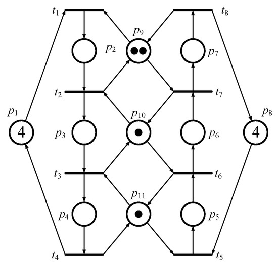
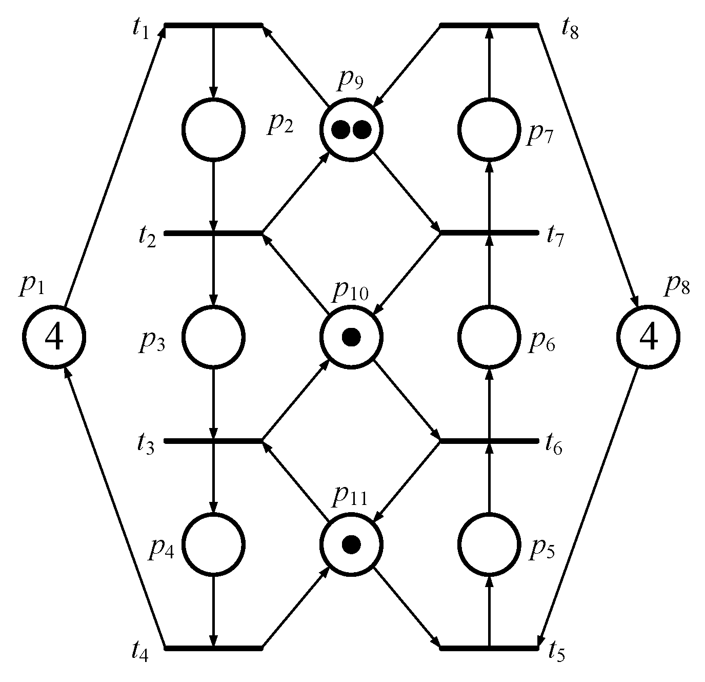
Figure 3.
Another simple PN model of FMS.
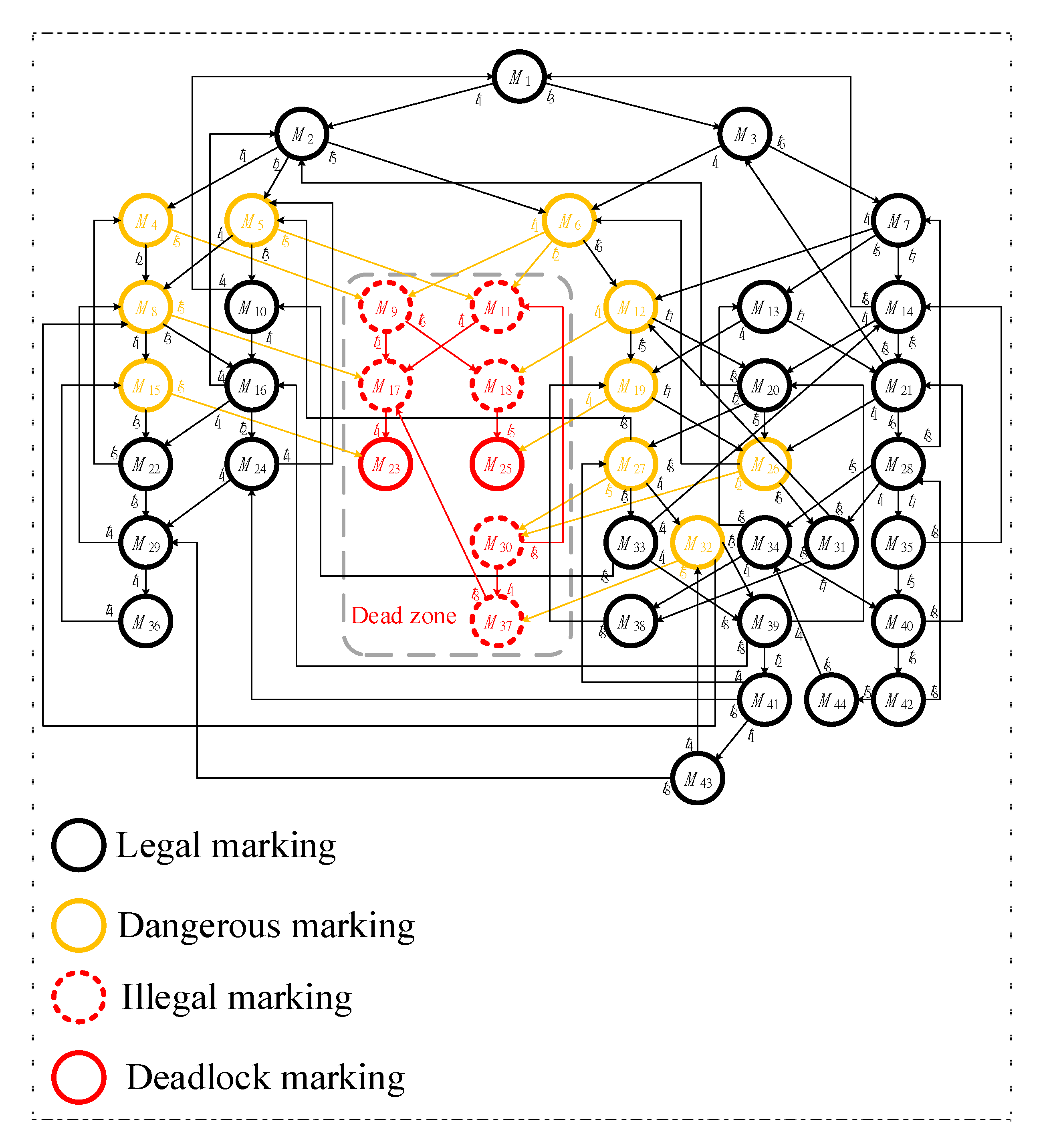
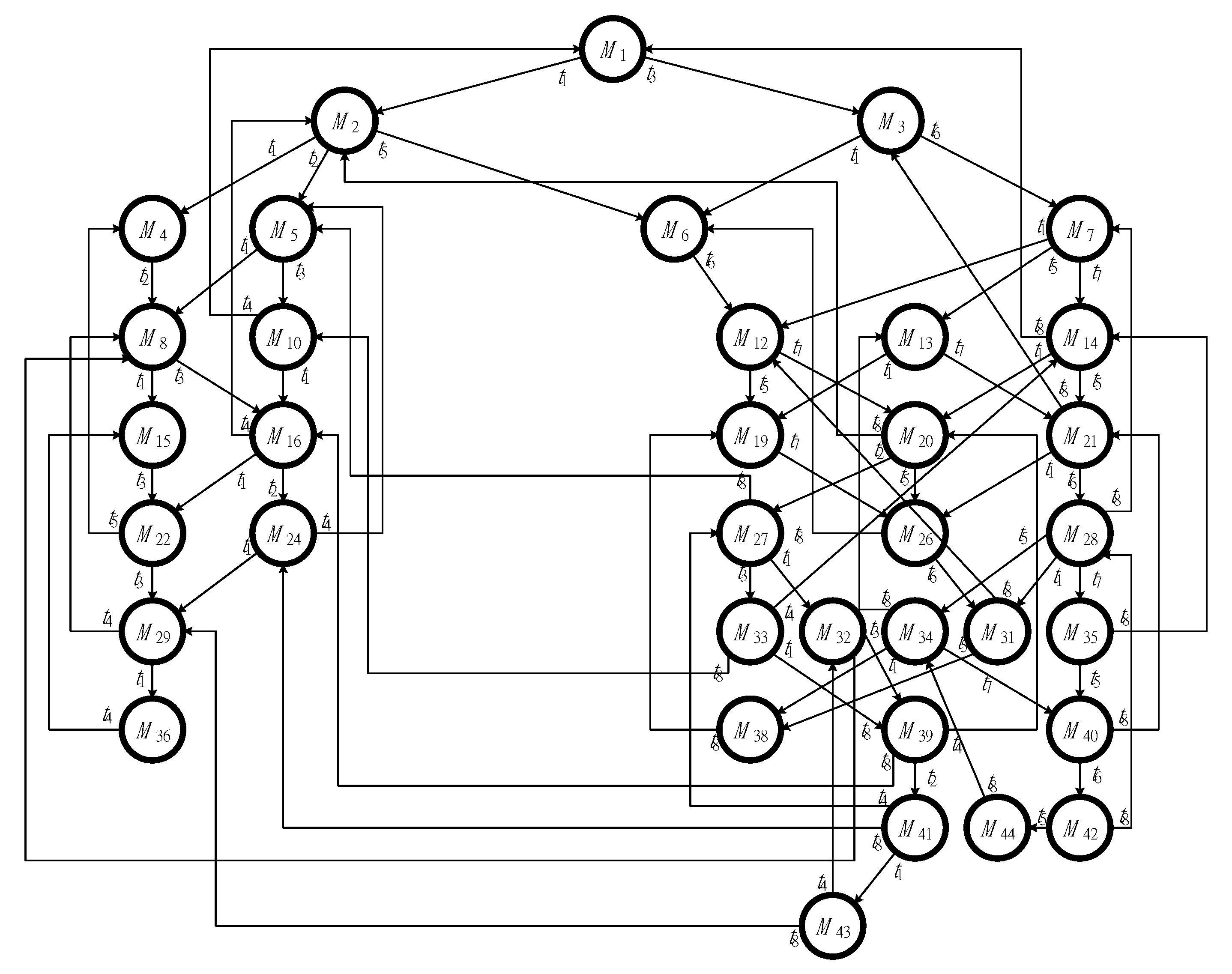
The first model, shown in Figure 3, has two idle places (i.e., p1 and p8), six activity places (i.e., p2-p7), and three resource places (i.e., p9-p11). Additionally, there are 44 reachable markings (i.e., M1-M44) in total, including 8 FBMs (i.e., M9, M11, M17, M18, M23, M25, M30, and M37) and 36 legal markings in its reachability graph, respectively. Its reachability graph is also shown in Figure 4.
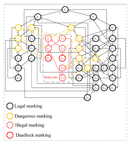
Figure 4.
The initial and full reachability graph of Figure 3.
According to our proposed algorithm in Section 3, and must be identified first. The computational efficiency of the conventional MFFP can then be further enhanced, based on Definitions 5 and 6, and the and in Example 1.
Next, following the vector covering approach, one can obtain = {(2p2 + p3 + p4), (p2 + p5 + p6 + p7), (p2 + p3 + p4 + p7), (p5 + p6 + 2p7)} and = {(2p2 + p5), (p3 + p5), (2p2 + p6)}, respectively. Please note that all the above markings present partial information. The detailed information is shown in Table 2 and Table 3.

Table 2.
Properties of eight First Bad Markings.

Table 3.
Properties of four Minimal Covering Sets.
Further, the IMFFP-2 for this model can then be obtained as follows.
The first iteration in our IMFFP-2:
.
.
.
In the following, solving the ILPP by using our proposed IMFFP-2, one can obtain two solutions. The first is ,, , , , and , and the second is , , , , , and .
Note that in fact the above two sets of controllers are the same since they can both make the system maximally permissive. Accordingly, one can just pick one set of controllers to process. For showing the two controllers are the same and the difference between this paper and [1], a second set of controllers is chosen by this paper. The second iteration is as follows.
The second iteration in the Improved MFFP-2:
.
.
.
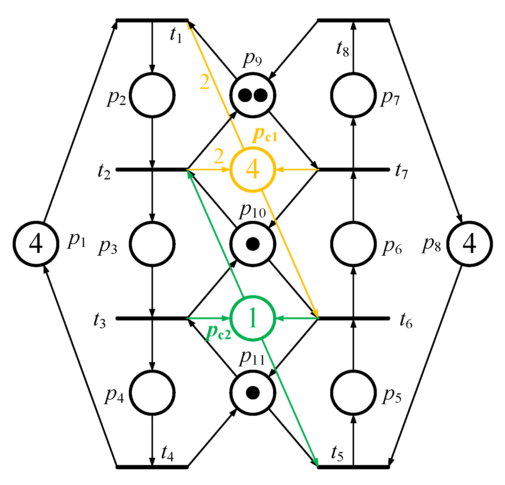
By running the above IMFFP-2 again, one new controller is obtained such that , , , and . Therefore, two PI controllers, and , are obtained. By putting the two control places into the original model (please refer to Figure 3), all 8 First Bad Markings are controlled while all 36 legal reachable markings are held. In other words, the PNM is not only live but also maximally permissive. Figure 5 and Figure 6 show the controlled system and its reachability graph, respectively.
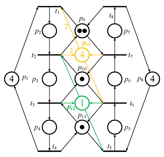
Figure 5.
Two controllers are added into the PN model in Figure 3.
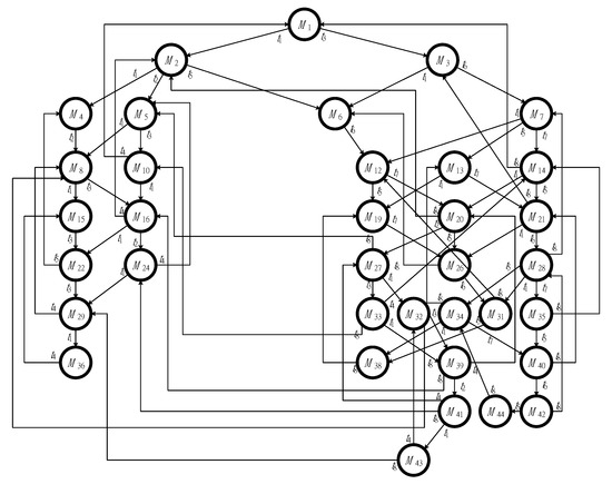
Figure 6.
The maximally permissive reachable states of Figure 3.
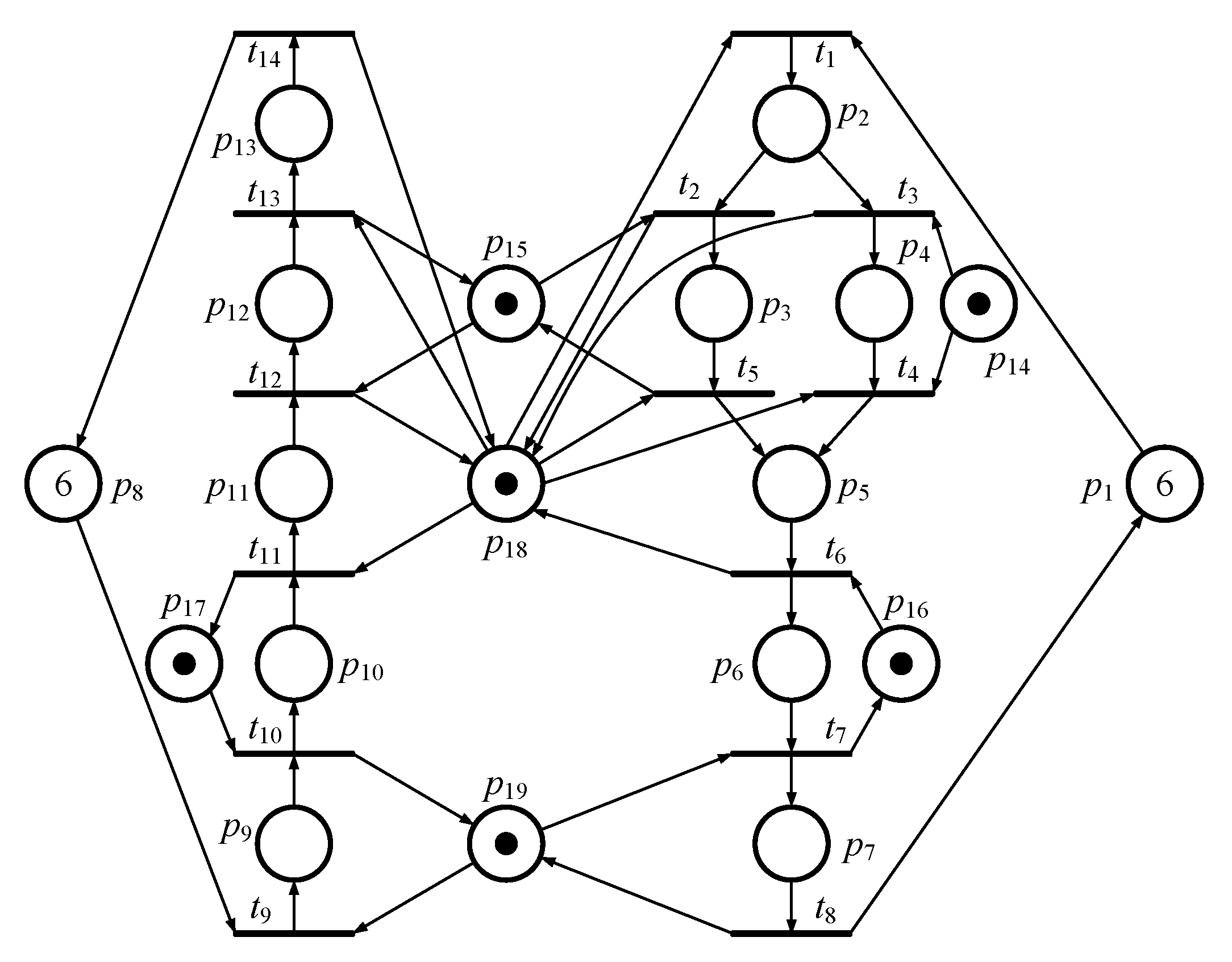
The second PNM of the FMS model shown in Figure 7 has 282 reachable markings in total, including and 205 legal markings and 77 illegal markings. Besides, there are 54 FBMs in the RG of the PNM according to the definition. By the vector covering approach, the markings that need to be considered in computation can then be reduced to 8 and 26 , respectively. Due to the limitation of space of this paper, the detailed information is presented in Table 4 and Table 5, respectively.
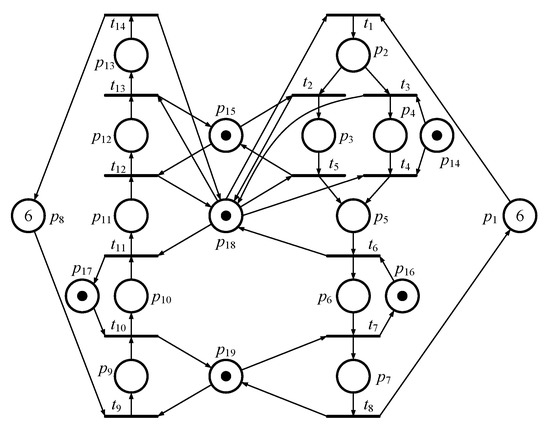
Figure 7.
The second PN model of FMS.

Table 4.
The properties of all First Bad Markings in Example 2.

Table 5.
The properties of 26 Minimal Covering Sets.
Additionally, based on Definitions 5 and 6, and in Example 2. Therefore, the first iteration for this example, using our IMFFP-2, is as follows:
S. t.
.
.
.
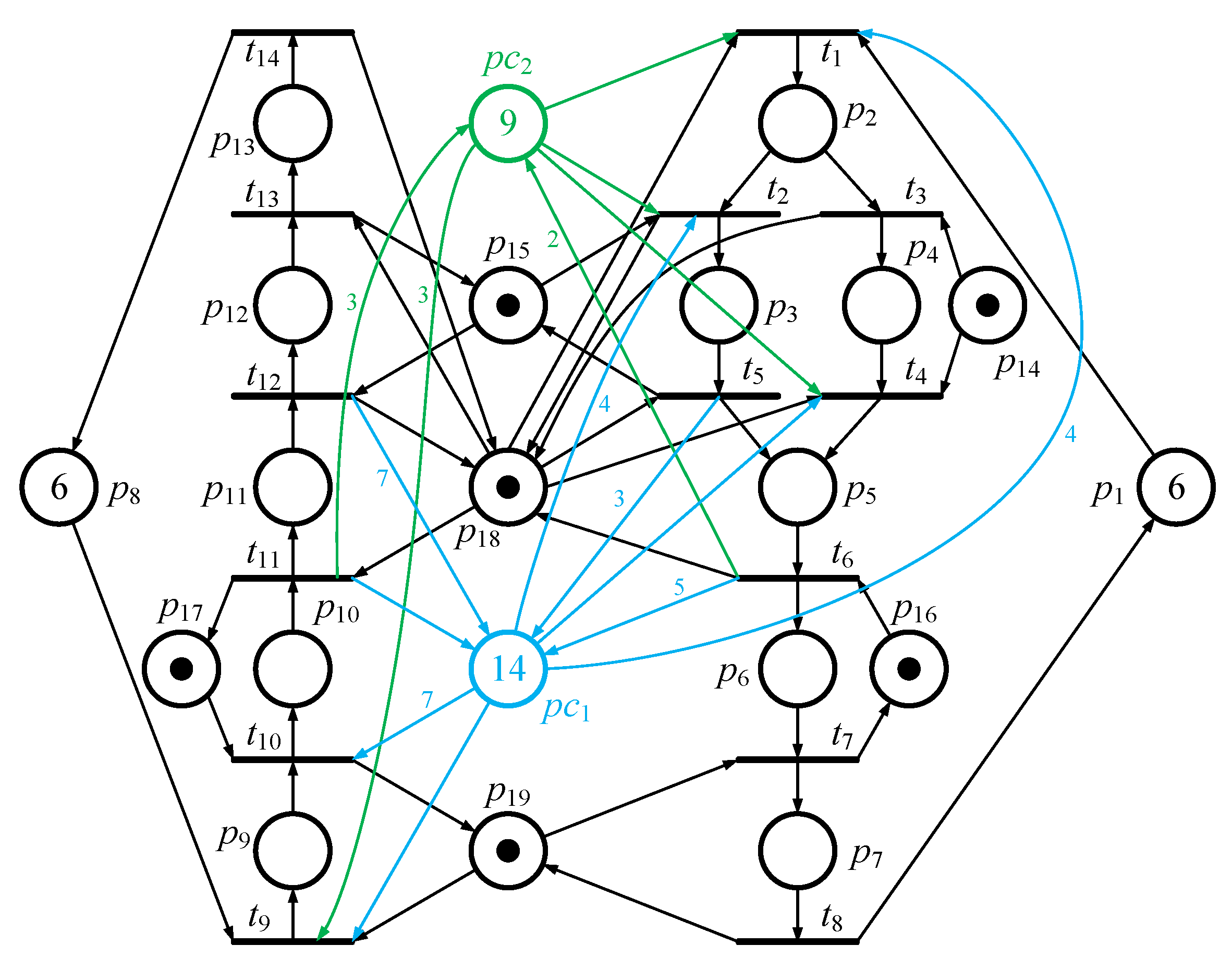
In the first iteration, there is a solution that l2 = 4, l3 = 8, l4 = 4, l5 = 5, l6 = 0, l7 = 0, l9 = 1, l10 = 1, l11 = 8, l12 = 7, l13 = 0, = 14, and ~=0. In other words, the first maximally permissive solution is , so five are hence forbidden. Then, the second iteration is considered, and a solution is obtained that l2 = 1, l3 = 2, l4 = 1, l5 = 2, l6 = 2, l7 = 0, l9 = 3, l10 = 3, l11 = 0, l12 = 0, l13 = 0, = 9, and ~ = 0. In other words, the second maximally permissive solution is . In the second iteration, the last three are forbidden. Finally, all eight are forbidden. Two controllers shown in Table 6 can then be obtained by the above two solutions. After adding the two control places into the second PN model, all the FBMs are then forbidden. Additionally, all illegal markings are also controlled. Two maximally permissive control places are shown in Figure 8.

Table 6.
The two optimal controllers of Example 2.
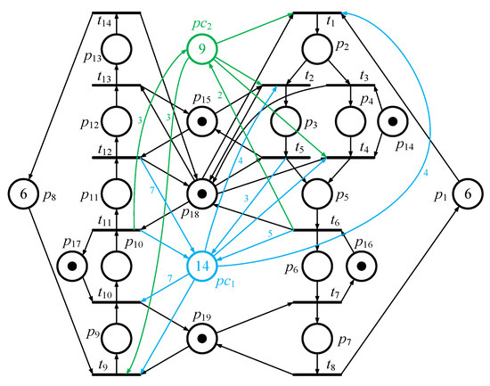
Figure 8.
Controlled system of the Petri model in Figure 7.
The third PN model taken from [6] is presented in Figure 9. Due to the limitation of space in this paper, the detailed information concerning the process of seeking controllers is not presented here. According to the definitions in this paper, there are 16 activity places that need to be calculated in MFFP. However, there are just 13 activity places that need to be calculated in IMFFP-2, since three PIPs (i.e., p4, p10, and p19) can be identified in Example 3.
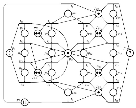
Figure 9.
The third Petri net model of FMS.
5. Comparison
In this section, we make a comparison with the conventional MFFP [1,2] in terms of the computational efficiency by comparing (1) system complexity and (2) time complexity. Here,MFFP represents the number of activity places needed by the MFFP method represents the number of identified in one PN-based system, and IMFFP represents the number of activity places needed by the IMFFP-2 method. Further, O(n?)MFFP and O(n?)IMFFP represent time complexity under MFFP and IMFFP-2, respectively. Firstly, based on Table 7 one can realize that there are 6, 11, and 16 variables (i.e., activity places) in Examples 1, 2, and 3, respectively, that need to be considered under the conventional MFFP control policy. However, there are just 4, 9, and 12 variables to consider since there are 2, 2, and 4 PPIP identified in Examples 1, 2, and 3, respectively, under IMFFP-2.

Table 7.
Comparison using system/time complexity in different examples.
Firstly, from the viewpoint of system complexity, the computational efficiency of IMFFP-2 must be better than conventional MFFP since the number of variables of IMFFP-2 is much less than in the conventional MFFP method. On the other hand, according to the book Introduction to the theory of computation (second edition) [55] and Wikipedia [56], the definition of time complexity for computer science is as follows: the time complexity of an algorithm can be expressed commonly by using big O notation “O”, which excludes coefficients and lower-order terms. When expressed this way, time complexity is said to be described asymptotically, i.e., as the input size goes to infinity. For instance, if the time required by an algorithm on all inputs of size n is at most 6n3 + 2n2 + 20n + 45 for any n (n is a variable), then obviously, there are four terms in total and the highest order term is 6n3. Thus, the asymptotic time complexity is O(n3). Therefore, the time complexity of Chen’s MFFP method in Example 1 could be viewed as O(n6). The time complexity of our IMFFP-2 is viewed as O(n4) based on Table 7. Similarly, the time complexity of Chen’s MFFP method in Example 2 is viewed as O(n11), and our IMFFP-2 is O(n9); the time complexity of Chen’s MFFP method in Example 3 is O(n16), and our IMFFP-2 is O(n13). Accordingly, in Examples 1 and 2, the computational efficiency of the proposed IMFFP-2 is 100 times better than that of the conventional MFFP control policy. In addition, in Example 3, the computational efficiency of the proposed IMFFP-2 is 1000 times better than that of the conventional MFFP method.
6. Conclusions
Solving flexible manufacturing systems’ deadlock problems is extremely difficult work. Just a few excellent mathematicians or researchers can work in this field. For decades, these outstanding pioneers have concentrated their efforts into proposing various algorithms to solve the deadlock problems of flexible manufacturing systems. In the authors’ previous study, the conventional MFFP method proposed by Chen et al. [1] seemed to be the best one (i.e., least control places and relative arcs) among all control place-based deadlock prevention policies in the existing literature. The greatest advantage of conventional MFFP is that just a few controllers are needed to hold the maximally permissive states in solving deadlock problems. In fact, the method could become better if (1) it could be applied for all kinds of nets not just for certain special nets or (2) we could further enhance its computational efficiency. Based on the above reason, firstly, in our previous paper we proposed an improved iteration method called IMFFP-1 [42] so that it could be used for all Petri nets’ general systems.
In the present paper, we further propose two novel concepts, namely, PIT and PIP, for the IMFFP-2. Once PIT or PIP is identified from a deadlock Petri nets model, one can bypass all PIP under the process of solving MFFP, and the computational time can hence be shortened. Undoubtedly, computational cost can then be decreased. Three examples prove that the IMFFP-2 is more efficient than the conventional MFFP in obtaining the same maximally permissive control places. Finally, and most importantly, in this paper, we redefine the conventional vector covering approach technology, named the improved vector covering approach technology (IVCAT), so that the definition can be solidified. We also identify the correct solution in the second example of Chen’s paper [1] so that all readers and researchers can easily follow Chen’s paper. In summary, the IMFFP-1 makes the conventional MFFP able to be used in all kinds of nets, and IMFFP-2 enhances the computational efficiency. In the future, we will further merge IMFFP-1 and IMFFP-2 so that it can be used for all kinds of PN-based FMSs and still have very great computational efficiency.
In the past, our research team has focused on developing more efficient algorithms in the existing methods, and obtained quite good results [9,15,34,35,36,37,40,42,43,47,48,49,57]. In our future works, four novel technologies [46,49,50,51] in this domain will be considered and we will aim to enhance their computational efficiency.
Author Contributions
Conceptualization, Y.-L.P. and C.-Y.T.; methodology, Y.-L.P., C.-W.T., and C.-Y.T.; software, C.-Y.T.; validation, Y.-L.P.; formal analysis, Y.-L.P.; investigation, Y.-L.P. and C.-W.T.; resources, C.-W.T. and J.-C.H.; data curation, Y.-L.P. and C.-Y.T.; writing—original draft preparation, Y.-L.P.; writing—review and editing, Y.-L.P.; visualization, C.-W.T. and J.-C.H.; supervision, Y.-L.P. All authors have read and agreed to the published version of the manuscript.
Funding
This research received no external funding.
Conflicts of Interest
The authors declare no conflict of interest.
References
- Chen, Y.; Li, Z.; Zhou, M. Behaviorally Optimal and Structurally Simple Liveness-Enforcing Supervisors of Flexible Manufacturing Systems. IEEE Trans. Syst. Man Cybern. Part A Syst. Hum. 2012, 42, 615–629. [Google Scholar] [CrossRef]
- Chen, Y.; Li, Z.; Khalgui, M.; Mosbahi, O. Design of a Maximally Permissive Liveness- Enforcing Petri Net Supervisor for Flexible Manufacturing Systems. IEEE Trans. Autom. Sci. Eng. 2011, 8, 374–393. [Google Scholar] [CrossRef]
- Yamalidou, K.; Moody, J.; Lemmon, M.; Antsaklis, P. Feedback control of petri nets based on place invariants. Automatica 1996, 32, 15–28. [Google Scholar] [CrossRef]
- Coffman, E.G.; Elphick, M.; Shoshani, A. System Deadlocks. ACM Comput. Surv. 1971, 3, 67–78. [Google Scholar] [CrossRef]
- Uzam, M.; Zhou, M. An Iterative Synthesis Approach to Petri Net-Based Deadlock Prevention Policy for Flexible Manufacturing Systems. IEEE Trans. Syst. Man Cybern. Part A Syst. Hum. 2007, 37, 362–371. [Google Scholar] [CrossRef]
- Ezpeleta, J.; Colom, J.; Martinez, J. A Petri net based deadlock prevention policy for flexible manufacturing systems. IEEE Trans. Robot. Autom. 1995, 11, 173–184. [Google Scholar] [CrossRef]
- Kumaran, T.K.; Chang, W.; Cho, H.; Wysk, R.A. A structured approach to deadlock detection, avoidance and resolution in flexible manufacturing systems. Int. J. Prod. Res. 1994, 32, 2361–2379. [Google Scholar] [CrossRef]
- Uzam, M.; Zhou, M.C. An improved iterative synthesis method for liveness enforcing supervisors of flexible manufacturing systems. Int. J. Prod. Res. 2006, 44, 1987–2030. [Google Scholar] [CrossRef]
- Pan, Y.L.; Huang, Y.S.; Jeng, M.; Chung, S.L. Enhancement of an efficient control policy for FMSs using the theory of regions and selective siphon method. Int. J. Adv. Manuf. Technol. 2012, 66, 1805–1815. [Google Scholar] [CrossRef]
- Luo, J.; Wu, W.; Su, H.; Chu, J. Supervisor Synthesis for Enforcing a Class of Generalized Mutual Exclusion Constraints on Petri Nets. IEEE Trans. Syst. Man Cybern. Part A Syst. Hum. 2009, 39, 1237–1246. [Google Scholar]
- Chen, Y.; Li, Z. Design of a maximally permissive liveness-enforcing supervisor with a compressed supervisory structure for flexible manufacturing systems. Automatica 2011, 47, 1028–1034. [Google Scholar] [CrossRef]
- Zhou, M.; Dicesare, F. Parallel and sequential mutual exclusions for petri net modeling of manufacturing systems with shared resources. IEEE Trans. Robot. Autom. 1991, 7, 515–527. [Google Scholar] [CrossRef]
- Huang, Y.; Jeng, M.; Xie, X.; Chung, S. Deadlock prevention policy based on Petri nets and siphons. Int. J. Prod. Res. 2001, 39, 283–305. [Google Scholar] [CrossRef]
- Huang, Y.S.; Jeng, M.; Xie, X.; Chung, D.H. Siphon-Based Deadlock Prevention Policy for Flexible Manufacturing Systems. IEEE Trans. Syst. Man Cybern. Part A Syst. Hum. 2006, 36, 1248–1256. [Google Scholar] [CrossRef]
- Pan, Y.L.; Jeng, M.D.; Chung, S.L.; Guo, Y.X. Computationally Improved Optimal Deadlock Prevention Policy for Linear Programming Problems of Flexible Manufacturing Systems. In Proceedings of the 2013 IEEE International Conference on Systems, Man, and Cybernetics, Manchester, UK, 13–16 October 2013. [Google Scholar]
- Zhou, M.; Mcdermott, K.; Patel, P. Petri net synthesis and analysis of a flexible manufacturing system cell. IEEE Trans. Syst. Man Cybern. 1993, 23, 523–531. [Google Scholar] [CrossRef]
- Li, Z.; Wang, A.; Wei, N. Liveness-Enforcing Supervisors for Flexible Manufacturing Systems with Multiple Resource Acquisitions. In Proceedings of the 2006 IEEE International Conference on Networking, Sensing and Control, Ft. Lauderdale, FL, USA, 23–25 April 2006. [Google Scholar]
- Li, Z.; Zhou, M. Elementary Siphons of Petri Nets and Their Application to Deadlock Prevention in Flexible Manufacturing Systems. IEEE Trans. Syst. Man Cybern. Part A Syst. Hum. 2004, 34, 38–51. [Google Scholar] [CrossRef]
- Iordache, M.; Moody, J.; Antsaklis, P. Synthesis of deadlock prevention supervisors using Petri nets. IEEE Trans. Robot. Autom. 2002, 18, 59–68. [Google Scholar] [CrossRef]
- Moody, J.O.; Antsaklis, P.J. Supervisory Control of Discrete Event Systems Using Petri Nets; Kluwer Academic Publishers: Boston, MA, USA, 1998. [Google Scholar]
- Jeng, M.D. A Petri net synthesis theory for modeling flexible manufacturing systems. IEEE Trans. Syst. Man Cybern. Part B (Cybern.) 1997, 27, 169–183. [Google Scholar] [CrossRef]
- Huang, Y.S. Design of Deadlock Prevention Supervisors Using Elementary Siphons. In Proceedings of the Multi Conference on “Computational Engineering in Systems Applications”, Beijing, China, 4–6 October 2006. [Google Scholar]
- Huang, Y.S. Deadlock Prevention for Sequence Resource Allocation Systems. J. Inf. Sci. Eng. 2007, 23, 215–231. [Google Scholar]
- Li, Z.W.; Hu, H.S.; Wang, A.R. Design of Liveness-Enforcing Supervisors for Flexible Manufacturing Systems Using Petri Nets. IEEE Trans. Syst. Man Cybern. Part C (Appl. Rev.) 2007, 37, 517–526. [Google Scholar] [CrossRef]
- Iordache, M.; Moody, J.; Antsaklis, P. A method for the synthesis of liveness enforcing supervisors in Petri nets. In Proceedings of the 2001 American Control Conference. (Cat. No. 01CH37148), Arlington, VA, USA, 25–27 June 2001. [Google Scholar]
- Park, J.; Reveliotis, S. Algebraic synthesis of efficient deadlock avoidance policies for sequential resource allocation systems. IEEE Trans. Robot. Autom. 2000, 16, 190–195. [Google Scholar] [CrossRef]
- Li, Z.W.; Liu, G.Y.; Hanisch, M.H.; Zhou, M.C. Deadlock prevention based on structure reuse of petri net supervisors for flexible manufacturing systems. IEEE Trans. Syst. Man Cybern. Part A Syst. Hum. 2012, 42, 178–191. [Google Scholar] [CrossRef]
- Uzam, M. An Optimal Deadlock Prevention Policy for Flexible Manufacturing Systems Using Petri Net Models with Resources and the Theory of Regions. Int. J. Adv. Manuf. Technol. 2002, 19, 192–208. [Google Scholar] [CrossRef]
- Uzam, M.; Zhou, M. Iterative synthesis of Petri net based deadlock prevention policy for flexible manufacturing systems. In Proceedings of the 2004 IEEE International Conference on Systems, Man and Cybernetics (IEEE Cat. No.04CH37583), The Hague, The Netherlands, 10–13 October 2004. [Google Scholar]
- Chen, Y.; Li, Z.; Barkaoui, K. Optimal Petri net supervisor with lowest implemental cost for flexible manufacturing systems. In Proceedings of the Etfa2011, Toulouse, France, 5–9 September 2011. [Google Scholar]
- Uzam, M. The use of the Petri net reduction approach for an optimal deadlock prevention policy for flexible manufacturing systems. Int. J. Adv. Manuf. Technol. 2004, 23, 204–219. [Google Scholar] [CrossRef]
- Uzam, M. Synthesis of feedback control elements for discrete event systems using Petri net models and theory of regions. Int. J. Adv. Manuf. Technol. 2004, 24, 48–69. [Google Scholar] [CrossRef]
- Ghaffari, A.; Rezg, N.; Xie, X. Design of a live and maximally permissive petri net controller using the theory of regions. IEEE Trans. Robot. Autom. 2003, 19, 137–142. [Google Scholar] [CrossRef]
- Huang, Y.S.; Pan, Y.L. Enhancement of an Efficient Liveness-Enforcing Supervisor for Flexible Manufacture Systems. Int. J. Adv. Manuf. Technol. 2010, 48, 725–737. [Google Scholar] [CrossRef]
- Huang, Y.S.; Pan, Y.L.; Zhou, M. Computationally Improved Optimal Deadlock Control Policy for Flexible Manufacturing Systems. IEEE Trans. Syst. Man Cybern. Part A Syst. Hum. 2012, 42, 404–415. [Google Scholar] [CrossRef]
- Pan, Y.L. An Efficient Deadlock Prevention Policy for Flexible Manufacturing Systems Using the Theory of Regions and Selective Siphon Method. Adv. Sci. Lett. 2012, 15, 342–345. [Google Scholar] [CrossRef]
- Huang, Y.S.; Pan, Y.L. An improved maximally permissive deadlock prevention policy based on the theory of regions and reduction approach. IET Control Theory Appl. 2011, 5, 1069–1078. [Google Scholar] [CrossRef]
- Li, Z.W.; Zhou, M.C.; Wu, N.Q. A Survey and Comparison of Petri Net-Based Deadlock Prevention Policies for Flexible Manufacturing Systems. IEEE Trans. Syst. Man Cybern. Part C (Appl. Rev.) 2008, 38, 173–188. [Google Scholar]
- Piroddi, L.; Cordone, R.; Fumagalli, I. Selective Siphon Control for Deadlock Prevention in Petri Nets. IEEE Trans. Syst. Man Cybern. Part A Syst. Hum. 2008, 38, 1337–1348. [Google Scholar] [CrossRef]
- Pan, Y.L.; Yang, C.F.; Jeng, M.D. Enhancement of Selective Siphon Control Method for Deadlock Prevention in FMSs. Math. Probl. Eng. 2015, 2015, 1–6. [Google Scholar]
- Moody, J.; Yamalidou, K.; Lemmon, M.; Antsaklis, P. Feedback control of Petri nets based on place invariants. In Proceedings of the 1994 33rd IEEE Conference on Decision and Control, Lake Buena Vista, FL, USA, 14–16 December 1994. [Google Scholar]
- Pan, Y.L.; Tseng, C.Y.; Row, T.C. Design of Improved Optimal or Suboptimal Deadlock Prevention for FMSs Based on Place Invariant and Reachability Graph Analysis Methods. J. Algorithms Comput. Technol. 2017, 11, 261–270. [Google Scholar] [CrossRef]
- Pan, Y.L.; Tseng, C.Y.; Huang, Y.S. Design of one computationally improved deadlock prevention based on MFFP technology in flexible manufacturing system. In Proceedings of the 2015 International Automatic Control Conference (CACS), Yilan, Taiwan, 18–20 Novembe 2015. [Google Scholar]
- Huang, Y.S.; Pan, Y.L.; Su, P.J. Transition-based Deadlock Detection and Recovery Policy for FMSs Using Graph Technique. ACM Trans. Embed. Comput. Syst. 2013, 12. [Google Scholar] [CrossRef]
- Xiuyan, Z.; Murat, U. Transition-based Deadlock Control Policy Using Reachability Graph for Flexible Manufacturing Systems. Adv. Mech. Eng. 2016, 8, 1–9. [Google Scholar]
- Chen, Y.F.; Li, Z.W.; Al-Ahmari, A.; Wu, N.; Qu, T. Deadlock recovery for flexible manufacturing systems modeled with Petri nets. Inf. Sci. 2017, 381, 290–303. [Google Scholar] [CrossRef]
- Row, C.; Pan, Y.L. Maximally Permissive Deadlock Prevention Policies for Flexible Manufacturing Systems Using Control Transition. Adv. Mech. Eng. 2018, 10, 1–10. [Google Scholar] [CrossRef]
- Row, T.C.; Hsu, W.M.; Pan, Y.L.; Wang, C.C. One Novel and Optimal Deadlock Recovery Policy for Flexible Manufacturing Systems Using Iterative Control Transitions Strategy. Math. Probl. Eng. 2019, 2019, 1–12. [Google Scholar] [CrossRef]
- Pan, Y.L. One Computational Innovation Transition-Based Recovery Policy for Flexible Manufacturing Systems Using Petri nets. Appl. Sci. 2020, 10, 2332. [Google Scholar] [CrossRef]
- Chen, Y.F.; Li, Z.W.; Barkaoui, K.; Wu, N.Q.; Zhou, M.C. Compact supervisory control of discrete event systems by Petri nets with data inhibitor arcs. IEEE Trans. Syst. Man Cybern. Syst. 2017, 47, 364–379. [Google Scholar] [CrossRef]
- Uzam, M.; Li, Z.W.; Gelen, G.; Zakariyya, R.S. A divide-and-conquer-method for the synthesis of liveness enforcing supervisors for flexible manufacturing systems. J. Intell. Manuf. 2016, 27, 1111–1129. [Google Scholar] [CrossRef]
- Murata, T. Petri nets: Properties, analysis and applications. Proc. IEEE 1989, 77, 541–580. [Google Scholar] [CrossRef]
- PN-Tools, A. Petri Net Analysis Tool, Ver. 1.0; Pedagogical University Rzesów: Warsaw, Poland, 1987. [Google Scholar]
- INA (Integrated Net Analyzer). A Software Tool for Analysis of Petri Nets. Version 2.2, 31.07. 2003. Available online: http://www.informatik.hu-berlin.de/~starke/ina.html (accessed on 31 July 2003).
- Sipser, M. Introduction to the Theory of Computation, 2nd ed.; Cengage Learning: Boston, MA, USA, 2013. [Google Scholar]
- “Time Complexity”. Wikipedia, 28 December 2017. Available online: https://en.wikipedia.org/wiki/Time_complexity (accessed on 11 January 2018).
- Pan, Y.L.; Huang, Y.S.; Weng, Y.S.; Wu, W.; Jeng, M.D. Computationally Improved Optimal Control Methodology for Linear Programming Problems of Flexible Manufacturing Systems. J. Appl. Math. 2013, 2013, 1–11. [Google Scholar] [CrossRef]
© 2020 by the authors. Licensee MDPI, Basel, Switzerland. This article is an open access article distributed under the terms and conditions of the Creative Commons Attribution (CC BY) license (http://creativecommons.org/licenses/by/4.0/).

