Article

In-Orbit Results and Attitude Analysis of the SNUGLITE Cube-Satellite

1
Mechanical and Aerospace Engineering, Institute of Advanced Machines and Design, Seoul National University, Seoul 08826, Korea
2
Telace Inc., Seoul 08505, Korea
3
Artificial Intelligence Research Section, Korea Aerospace Research Institute, Daejeon 34133, Korea
*
Author to whom correspondence should be addressed.
Appl. Sci. 2020, 10(7), 2507; https://doi.org/10.3390/app10072507
Submission received: 17 March 2020 / Accepted: 2 April 2020 / Published: 5 April 2020
(This article belongs to the Section Mechanical Engineering)

Abstract

:
SNUGLITE (Seoul National University Global navigation satellite system Laboratory satellITE) is a two-unit cube satellite (CubeSat) with dimensions 10 × 10 × 23 cm that requires an attitude system for missions and ground station telecommunication. A linear-quadratic-Gaussian-based optimal attitude system for the CubeSat platform has been developed using low-cost sensors, with the in-orbit verification of the attitude system being is one of main study objectives. Since launch, the SNUGLITE CubeSat has continuously broadcast in-orbit status information. In this study, a methodology for the analysis of in-orbit attitude estimation results using received data is presented, and this was achieved by comparing two sun-pointing vectors, i.e., the sun-pointing vector calculated using estimated attitude with the positions of the sun and the satellite and the reference vector generated by the power levels of the solar panels. Because the satellite position was required for the attitude analysis, the verification of the performance of the own-developed on-board Global Positioning System (GPS) receiver is also briefly described. Analyses indicate that the attitude estimation of the SNUGLITE CubeSat has achieved an in-orbit real-time pointing accuracy with a root mean square of 6.1°.

1. Introduction

A cube-satellite (CubeSat) standard has been developed for the design of pico-satellites and nano-satellites, with the objectives being to reduce cost and development time, increase accessibility to space, and sustain frequent launches [1]. The CubeSat platform allows students to conceive, design, implement, test, and operate a complete spacecraft in space, often using commercial off-the-shelf (COTS) components for educational purposes [2,3], and it also allows developers to test payloads and platforms in orbit at a reasonable price. Various missions and projects have been performed using CubeSats for scientific, private and government purposes, and the number of launches and operations is on the rise [4]. MinXSS-1 CubeSat’s science objective is to measure the soft x-ray energy distribution from the sun [5]. The primary mission goal of CSTB1 was to accelerate the maturity of components and subsystems, as well as to accelerate the infrastructure and operations of the CubeSat platform [6]. The primary objective of the Radio Aurora Explorer (RAX) mission is to study the formation of magnetic field-aligned plasma irregulars in the polar lower ionosphere [7,8]. The main mission of the ESTCube-1 CubeSat is to conduct the first in-orbit electric solar wind sail experiment [9]. Presently, industrial companies, such as Planet Labs Inc. [10] and Spire [11], have started to open commercial services, including the use of CubeSat constellations. Planet Labs Inc. operates more than a hundred CubeSats for Earth-imaging, and Spire’s missions are ship tracking and weather forecasts.
The statistics of the CubeSat missions show that while it has been primarily Earth-imaging and science missions that have been conducted, technical demonstrations, communications, education, and military missions have also been performed [4]. According to the mission or telecommunication with the ground station, the attitude system of the CubeSat is required to point to the target area or ground station. Legacy full-scale satellite attitude systems are large and expensive to install on the CubeSat-class platform, where mass, size, and power are limited [12]. To achieve accurate and precise attitude, an attitude system using a star-tracker was developed and applied on the CubeSat platform, and its in-orbit validation was performed [5]. It should be noted, however, that applying a star-tracker on the CubeSat platform is very expensive at present. Attitude systems that use low-cost sensors have been developed [6,7,8,9,12], taking advantage of the relative cost-effectiveness of the CubeSat platform in allowing access to space. The RAX-1 and RAX-2 CubeSats use COTS magnetometers, as well as coarse sun-sensors (photodiodes), micro electro mechanical systems (MEMS)-rate gyroscopes, and an extended Kalman filter (EKF). The in-orbit performance of attitude estimation was analyzed with the error covariance of the filter, which uses onboard calibration [7,8]. Boeing’s CSTB1 also used low-cost sensors for attitude estimation, and its performance was validated using onboard camera images taken at the time of attitude estimation [6]. The attitude determination system of ESTCube-1 was also validated by comparing 15 samples of the onboard camera image and estimated attitude [9].
We developed the SNUGLITE (Seoul National University Global navigation satellite system Laboratory satellITE) CubeSat with these objectives in mind: (1) to monitor the disturbance of the ionosphere and the Earth’s magnetic field that is caused by seismic events, (2) to develop and verify the in-orbit operation of the linear quadratic Gaussian (LQG)-based attitude system, and (3) to provide a technical demonstration of the own-developed dual-frequency Global Positioning System (GPS) receiver for the CubeSat platform. The SNUGLITE CubeSat was successfully launched and settled in orbit on December 03, 2018, and it has broadcast its status data continuously for more than a year, with signals being received worldwide, both at the SNUGLITE ground station and at amateur ground stations [13]. The received data include information on the status of the SNUGLITE, estimated attitude information, and the calculated GPS results.
The attitude system for the SNUGLITE CubeSat consists of low-cost sensors and actuators: coarse sun-sensors (five-photodiodes), a three-axis magnetometer, and a three-axis gyroscope, as attitude sensors, and three-axis magnetorquers as actuators. One of the contributions of this study is that the LQG-based attitude system for the Cubesat platform was developed for an optimal solution operable for the in-orbit environment. The LQG controller is an optimal controller where a quadratic cost function is minimized when the plant has random initial conditions, white noise disturbance input, and white measurement noise [14]. The solution of the LQG problem combines the solutions of the deterministic linear quadratic regulator (LQR) problem and the optimal state estimation problem using the linear-quadratic state estimator, the Kalman filter. In the SNUGLITE CubeSat, the filter and controller are implemented in an onboard computer that performs in real-time. Previous researchers have derived the solution of the LQG attitude system for the CubeSat platform and performed simulation-based analyses [15,16], while others have performed hardware-based, single-axis verification experiments using wire and a Helmholtz cage [17]. This paper describes and analyzes the in-orbit real-time performance of the attitude estimation using the LQG system. Though LQG was considered for the attitude system, only estimation results could be analyzed properly using the received status data. Therefore, the focus of this study was the performance analysis of the attitude estimation.
Because previous studies have limitations in representing the generalized attitude estimation performance, another contribution is the proposed evaluation method for the in-orbit estimation performance for the CubeSat platform. The attitude systems of the RAX-1 and RAX-2 CubeSats were quantified by the state error covariance of the estimation filter without reference attitude [8]. Camera images were utilized to generate the reference attitude [6,9]. However, the number of image samples (less than 15 samples) was not sufficient to evaluate the attitude estimation performance. In this study, the estimation performance was investigated by comparing two sun-pointing vectors: the calculated sun-pointing vector by estimated attitude and the reference sun-pointing vector by the generated power levels of the solar panel on each side. Therefore, a sufficient number of samples of reference attitude were considered for the estimation analysis. To generate the sun-pointing vector in the body-frame using the estimated attitude, we utilized the filtered results of the magnetometers, gyroscopes, and photodiodes, as well as the positions of the satellite and the sun. For the reference vector, power levels, which are independent measurements from the photodiodes—although both measure the strength of the sunlight—were normalized to point to the sun in the body-frame. Error vectors between two sun-pointing vectors and their difference in angle were mainly investigated for the performance analysis of the attitude estimation.
To calculate the sun-pointing vector utilizing estimated attitude, the position of the CubeSat was determined from the results of the GPS receiver. Because the GPS receiver was newly developed for the SNUGLITE CubeSat, its validation was also required. Given that the fundamental operability of GPS receivers has already been presented [18], this paper describes newly found characteristics, such as altitude variations by perturbations.
This paper describes the results of the technical mission of the SNUGLITE CubeSat. A brief introduction to the SNUGLITE project is given, and the specification of the CubeSat, payloads, and the structure of broadcasting data are included in Section 2. The attitude system of the SNUGLITE CubeSat is described, and a method to analyze the performance of the attitude estimation is also presented in Section 2. Subsequently, the GPS data received from the SNUGLITE as well as the status of the CubeSat are presented in Section 3. In-orbit results of the attitude estimation are also evaluated and discussed in Section 3 and Section 4, respectively. In Section 4 (Discussion), the attitude system is also compared with that of previous studies. Finally, Section 5 summarizes the study and provides suggestions for future work.

2. Materials and Methods

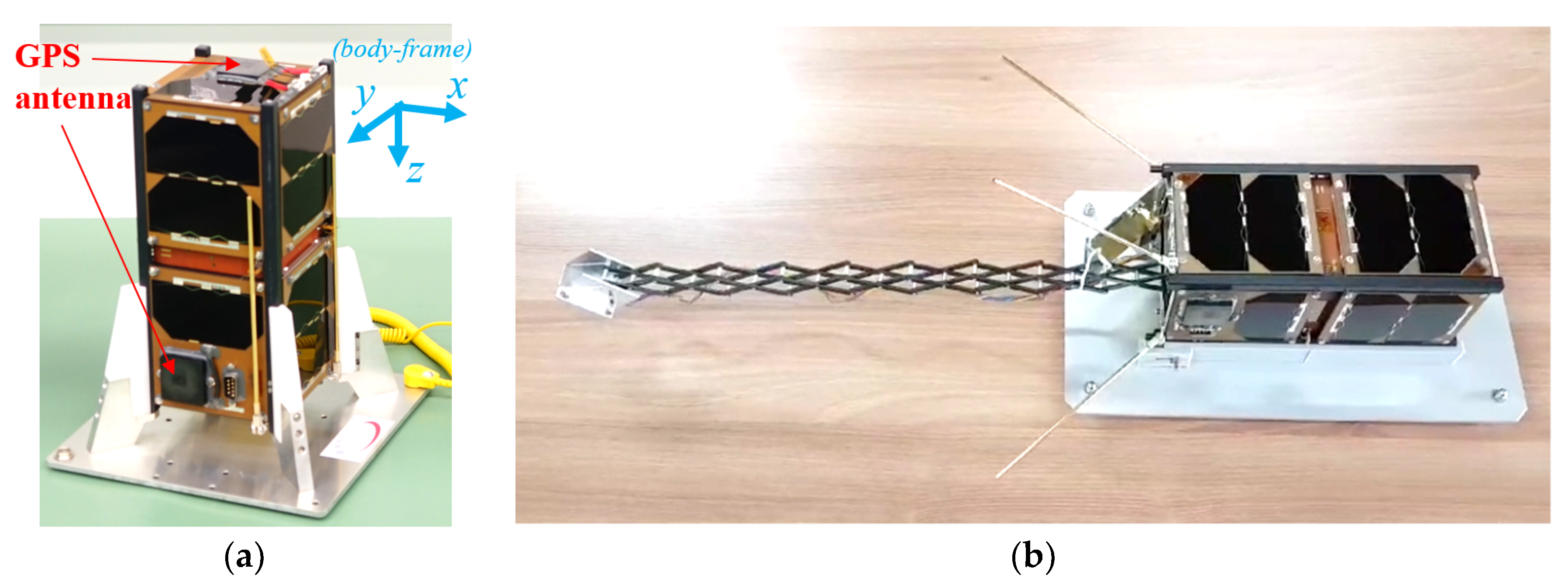
2.1. SNUGLITE CubeSat Project

SNUGLITE’s shape is described in Figure 1. The project was selected at the 2015 CubeSat competition by the Korea Aerospace Research Institute. After three years of development, SNUGLITE was launched on December 3, 2018. It settled successfully in the target orbit, which is sun-synchronous at an altitude of 575 km. SNUGLITE’s designated satellite number given by the North American Aerospace Defense Command (NORAD) is 43,784.
SNUGLITE is a 2-unit CubeSat whose specifications are described in Table 1. One of the scientific missions of the SNUGLITE CubeSat is to monitor the disturbance of the ionosphere and the magnetic field by seismic events, such as earthquakes, volcanoes, and tsunamis. SNUGLITE has two dual-frequency GPS receivers. The first receiver, which is for satellite positioning, has its antenna mounted at the top of the satellite in the −z direction of Figure 1 to the zenith direction. The second GPS antenna is mounted on the side of the CubeSat in the +y direction in order to measure the ionospheric delay on the path from other GPS satellites to the SNUGLITE.
One of the technical missions of the SNUGLITE CubeSat is to verify the in-orbit operation of the on-board L1/L2C GPS receivers, which we developed in co-operation with TelAce Inc. (Seoul, Korea). The receivers are shown in Figure 2. Another technical objective is to develop an LQG-based attitude system.
Since launch, the SNUGLITE CubeSat has continuously broadcast its status data in beacons. Ground stations in Asia, Europe, North America, and South America have been receiving the beacons. The ground facility for the SNUGLITE team was constructed in Seoul National University using a conventional amateur satellite transceiver, antenna modules, and amplifiers to communicate with the satellite.
However, an uplink problem occurred, and the SNUGLITE CubeSat became unresponsive to tele-commands from the ground station. Given that commands from the ground station are required to initiate the scientific mission, the SNUGLITE CubeSat has not proceeded to ‘observation mode’ for ionosphere and magnetic field monitoring, and it is currently in standby mode.
Though a problem has occurred in performing the scientific mission, the analysis of the attitude system can be still be performed using the received status data, as they include the estimated attitude, the calculated position and velocity measured by GPS receivers, and other related information.

2.2. Beacon and Telemetry Data

The SNUGLITE CubeSat has two kinds of beacon formats to efficiently broadcast the satellite survival and status information, namely the simple beacon (which transmits every 10 s) and the full beacon (which transmits every 30 s). The simple beacon broadcasts basic essential data comprising ‘time,’ ‘GPS receiver,’ ‘battery status flag,’ and ‘battery voltage,’ while the full beacon broadcasts detailed information such as satellite temperature, estimated attitude, power consumption and generation, and other satellite status flags. Table 2 describes the information relayed by both beacons.

2.3. Attitude System of SNUGLITE

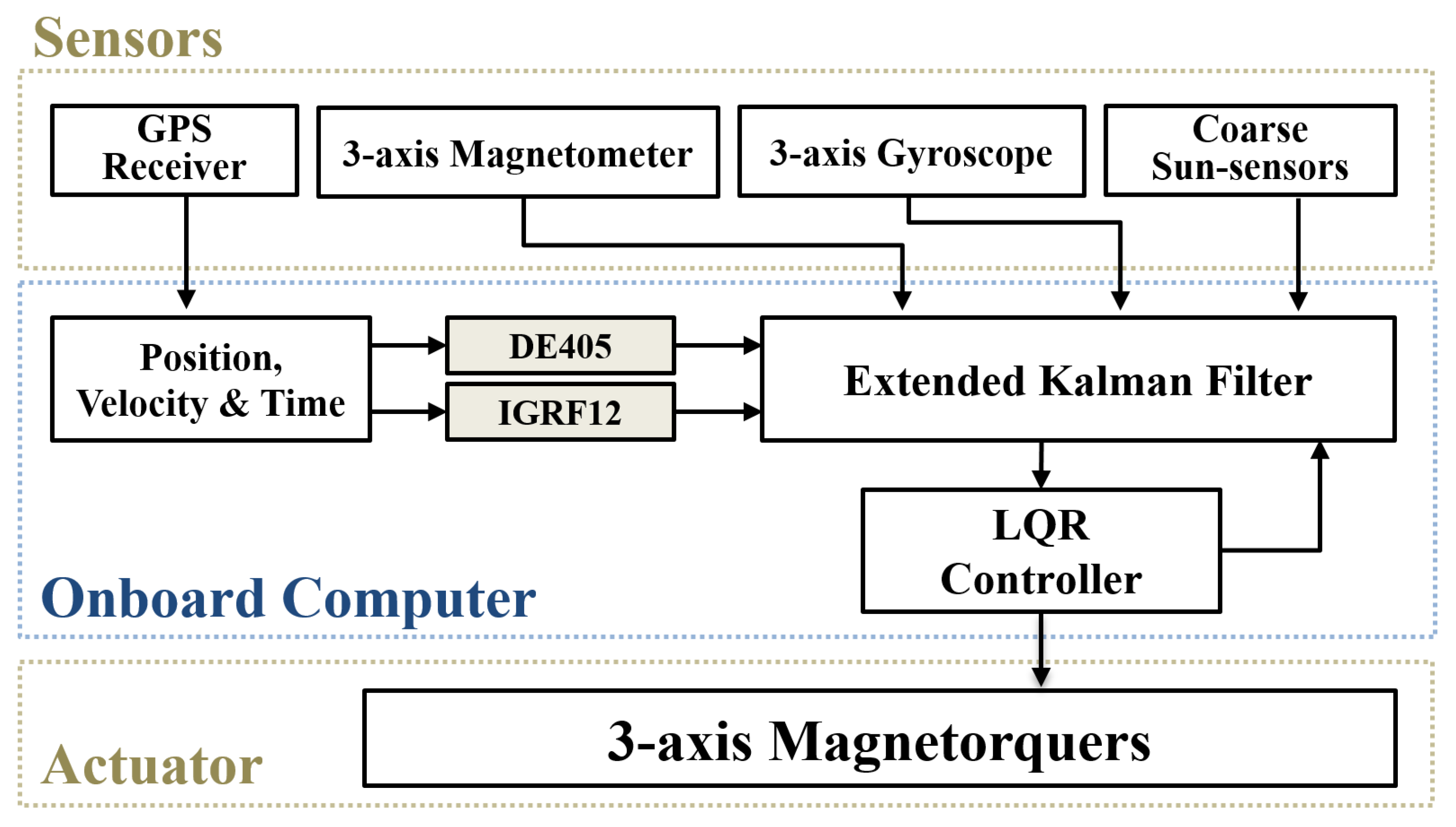
2.3.1. Attitude System Configuration

The attitude system of the SNUGLITE was programmed to maintain the +z direction of the body-frame, as described in Figure 1, pointing to the nadir-direction and the +x direction of the body-frame aligned along-track with the orbit. The LQG-based attitude system was designed using coarse sun-sensors, a 3-axis magnetometer and a 3-axis gyroscope as sensors, and 3-axis magnetorquers as actuators [16,19]. A triple-axis MEMS MPU-3300 gyroscope by InvenSense and an HMC5843 low-cost three-axis magnetometer by Honeywell are utilized. Five SLCD-61N8 photodiodes are attached to the solar panels at +x, −x, +y, −y, and −z sides to work as coarse sun-sensors. The dipole momentum of the utilized magnetorquers is approximately 0.038 Am2, and three magnetorquers are integrated into the solar panels at each axis.
The block diagram for the SNUGLITE attitude system is shown in Figure 3. Position, velocity, and time were input into DE405 and IGRF12 models to generate reference vectors of the sun vector and the magnetic field vector. DE405 is NASA’s Development Ephemeris, and IGRF12 is a model of the International Geomagnetic Reference Field. Measurements from the coarse sun-sensors, magnetometer, and gyroscope, were compared to the reference vectors for attitude estimation. The 3-axis magnetorquers acted as the actuators for the SNUGLITE CubeSat. Sensing cannot be conducted when the magnetorquers are in operation, because both attitude determination and control utilize magnetic information. Therefore, sensing and actuating of the magnetic field are performed alternately every other second. Algorithms of the attitude system are implemented in the onboard computer, a 32-bit AVR32 processor. In the SNUGLITE CubeSat, the attitude, the command, and the data handling processes are conducted on the same computer in real-time.
In this paper, we describe the attitude estimation by using an EKF in an LQG-based attitude system. The derivation and detailed description of the attitude control algorithm are given in [17].

2.3.2. Onboard Attitude Determination Algorithm

Sensing measurements from the gyroscope, magnetometer, and coarse sun-sensors must be calibrated properly for attitude estimation. The magnetometer hard-iron and soft-iron calibration was done before shipping to the launch site. In addition, temperature, and current compensation by power generation by the solar panels were also considered for magnetometer sensing [17]. The sine curvature of the photodiodes for the coarse sun-sensors was calibrated based on experimental results [20]. For gyroscope measurements, biases at each axis were implanted in the estimation filter as states. A real-time calibration process for the biases is performed in orbit.
EKF was utilized as shown in Equations (1)–(4), which represent the states of the filter:
x ( t ) = [ q ω b ] T
q = [ q 0 q 1 q 2 q 3 ] T
ω = [ ω x ω y ω z ] T
b = [ b x b y b z ] T
where q is the quaternion vector, ω is the vector of three-axis angular velocity, and b is the bias vector of gyroscopes. The non-linear system equation for the estimation is expressed as Equation (5), and Ω ( · ) is defined as Equation (6).
[ q ˙ ω ˙ b ˙ ] = [ 1 2 Ω ( ω L B B ) q I ¯ ¯ 1 ( μ × B ω × ( I ¯ ¯ ω ) ) 0 3 × 3 ] + [ 0 η drift η bias ]
Ω ( ω ) [ 0 ω x ω y ω z ω x 0 ω z ω y ω y ω z 0 ω x ω z ω y ω x 0 ]
where ω L B B is the angular velocity of the body frame with respect to the local frame, I ¯ ¯ is the moment of the inertia dyadic of the SNUGLITE CubeSat, μ is the magnetorquer vector for control input, and B is the strength of the local magnetic field. η drift and η bias are the process noises for the system equation. The system can be expressed as Equation (7). The process noises include various disturbances; however, they are modeled as Gaussian white noise in Equations (8) and (9).
x ˙ ( t ) = f ( x ( t ) , μ ( t ) ) + w ( t )
w ( t ) ~ N ( 0 , Q )
Q = [ 0 0 0 0 ( σ gg 2 + σ sr 2 + σ ad 2 + σ mdt 2 ) I 3 × 3 0 0 0 ( σ rrw 2 ) I 3 × 3 ]
where σ gg is the process noise from the gravity gradient, σ sr is the process noise from the solar radiation pressure, σ ad is the process noise from the air drag, and σ mdt is the process noise from the residual dipole moment. σ rrw is the rate random walk process noise. Detailed values and descriptions for the criteria related to the variance matrix Q can be found in [17].
The non-linear measurement equations are shown in Equations (10)–(14).
z ( t ) = h ( x ( t ) ) + v ( t )
z ( t ) = [ B meas s meas ω meas ] T
h ( x ( t ) ) = [ R local body R ECI local R ECEF ECI R NED ECEF B IGRF | B IGRF | R local body R ECI local s DE 405 ω + b ]
v ( t ) ~ N ( 0 , R )
R = [ σ mag 2 / | B IGRF | 2 I 3 × 3 0 ¯ 0 ¯ 0 ¯ σ sun 2 I 3 × 3 0 ¯ 0 ¯ 0 ¯ σ arw 2 I 3 × 3 ]
where z is the measurement state vector, B meas is the measurement vector of the 3-axis magnetometer, s meas is the coarse sun-sensor vector, and ω meas is the vector measured by the 3-axis gyroscope. R α β is the rotation matrix from the α–frame to the β–frame. B IGRF is the local magnetic field based on the IGRF-12 model, and s DE 405 is the sun vector calculated from the DE405 model. The satellite position utilized for IGRF and DE405 is calculated based on information given by the on-board GPS receiver. The variance matrix for R is formed as Equation (14) considering Gaussian white noise. In Equation (14), σ sun and σ arw are the sun sensor measurement noise and angular random walk measurement noise, respectively. The setting values for matrix R are described in [17].
Using Equations (7) and (10), the linearized system equations for the EKF can be described by Equations (15) and (16), and the measurement equations for the EKF can be described by Equations (17) and (18), respectively.
x ˙ = F x + G u + Γ w
w ( t ) ~ N ( 0 , Q )
z = H x + v
v ( t ) ~ N ( 0 , R )
where F and G in Equation (15) are partial derivatives of f ( x ( t ) ,   μ ( t ) ) with respect to x and u, respectively. Г is a partial derivative of w with respect to η. H in Equation (17) is a partial derivative of h(x) with respect to x. The continuous EKF is discretized using the first-order Van-Loan algorithm, as described in [21], to consider the processing capacity of the onboard computer. When the magnetorquers are in operation, the magnetometer vector in Equation (11) is excluded during measurement update because the magnetorquer influences the measurements of the magnetic sensor. Similarly, the sun sensor vector in Equation (11) is also excluded during measurement update in the eclipse area. Further descriptions of how the EKF was developed and calculated may be found in [22].

2.3.3. Attitude Estimation Analysis Method

The full beacon from the SNUGLITE CubeSat includes estimated satellite attitude, as described in Table 2. However, it is required to generate any reference for the performance analysis of the attitude estimation. In this paper, the amount of power generated on each side of the CubeSat was utilized to form the reference sun vector in the body frame. The reference sun vector by power generation is compared to the estimated sun vector generated by the estimated attitude, as well as the positions of the satellite and the sun at each epoch. Detailed steps are described below in Equations (19)–(27).
The reference sun vector can be generated as
s meas . body = [ sign ( T x + T x ) P meas . x C x sign ( T y + T y ) P meas . y C y P meas . z C z ] T
s ^ meas . body = s meas . body s meas . body
where s meas . body is a reference sun-vector and s ^ meas . body is a unit reference sun-vector. P meas . x ,   P meas . y , and P meas . z denote generated powers at each axis calculated using the solar-panel input voltages and currents listed in Table 2. T x + ,   T x ,   T y + , and T y denote the temperatures of each solar panel in the body-frame, as described in Table 2. ‘sign’ in Equation (19) is a function to return the sign of a number. According to the power module structure in the full beacon, ground users would know the amount of power generation at each axis. The temperatures of the solar-panel are needed to distinguish the side of the axis that is facing the sun. It is primarily correct to assume that the temperature of the solar panel facing the sun is high. As there is no solar panel in the z+ side, power generation at the z-axis is always from the z− solar panel.
C x ,   C y , and C z are the number of solar cells on each side. They were used to normalize the power generation on each side to generate the unit sun-pointing vector. C x is four, and C z is one because there is only one solar cell in z− solar panel, as shown in Figure 1. C y is selected based on which side between y+ and y− is facing the sun as in Equation (21) because there is one less solar cell in the y+ direction on which to mount the GPS antenna.
C x = 4 C y = { 3 if   T y + > T y 4 else C z = 1
The estimated sun vector is derived as equations:
s ^ ECI = x sun , DE 405 ECI x sat . , GPS ECI x sun , DE 405 ECI x sat . , GPS ECI
s ^ estm . body = R ECI body s ^ ECI
where s ^ ECI is a unit sun vector in the Earth-centered inertial (ECI) frame and s ^ estm . body is a sun vector estimated in the body frame. x sun , DE 405 ECI is the position of the sun calculated using the DE405 model, and x sat . , GPS ECI is the position of the SNUGLITE in the ECI frame that is found by using the output of the GPS receiver mentioned in Table 2. R ECI body is a rotation matrix from the ECI to the body-frame. The rotation matrix is comprised of two parts, as shown in Equation (24):
R ECI body = R local body R ECI local
where R ECI local is a rotation matrix from the ECI frame to the local orbital plane frame and R local body is a rotation matrix from the local orbital frame to the body frame.
To generate R ECI local , the equinox-based transformation method is utilized with Earth orientation parameters provided by the International Earth Rotation and Reference System [23]. For the rotation matrix from the local frame to the body frame, R local body , the estimated attitude of quaternion parameters, calculated in the attitude system of the CubeSat and denoted as ‘estimate attitude’ in the full beacon, is utilized in Equation (25):
R local body = [ q 0 2 + q 1 2 q 2 2 q 3 2 2 ( q 1 q 2 + q 0 q 3 ) 2 ( q 1 q 3 q 0 q 2 ) 2 ( q 1 q 2 q 0 q 3 ) q 0 2 q 1 2 + q 2 2 q 3 2 2 ( q 2 q 3 + q 0 q 1 ) 2 ( q 1 q 3 + q 0 q 2 ) 2 ( q 2 q 3 q 0 q 1 ) q 0 2 q 1 2 q 2 2 + q 3 2 ]
The performance analysis of the attitude estimation of the SNUGLITE CubeSat was conducted using the two equations below:
δ s ^ = s ^ meas . body s ^ estm . body
δ θ ^ = arccos ( s ^ meas . body s ^ estm . body )
where δ s ^ is an error vector between the reference sun vector and the estimated sun vector, and δ θ ^ is the angle between two vectors.

3. In-Orbit Results

3.1. Satellite Status

The following section describes the satellite status data required for the analysis of the attitude system. Calculated GPS results, battery voltage level, and power generation were evaluated to determine whether the attitude system was performing efficiently.

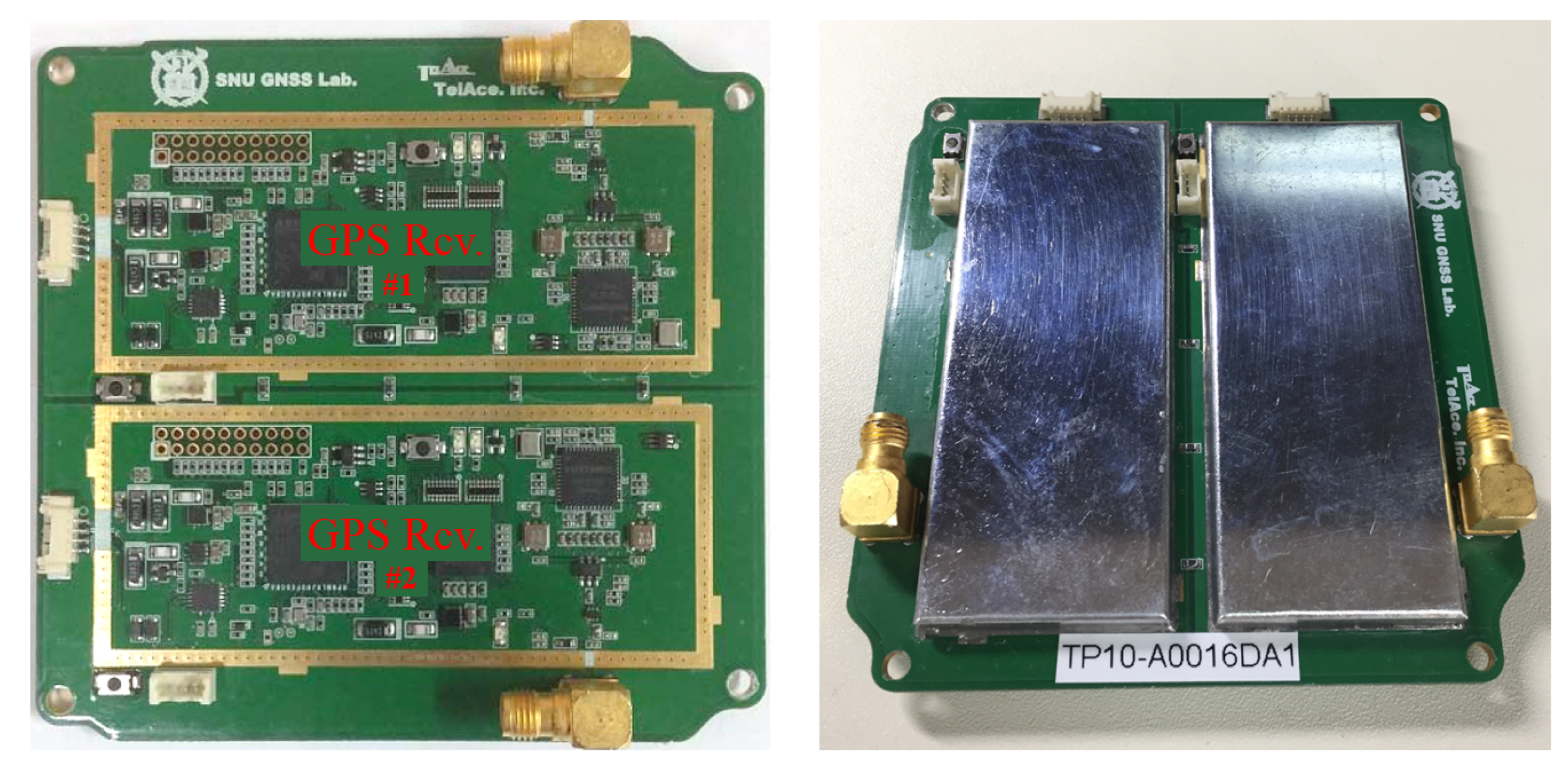
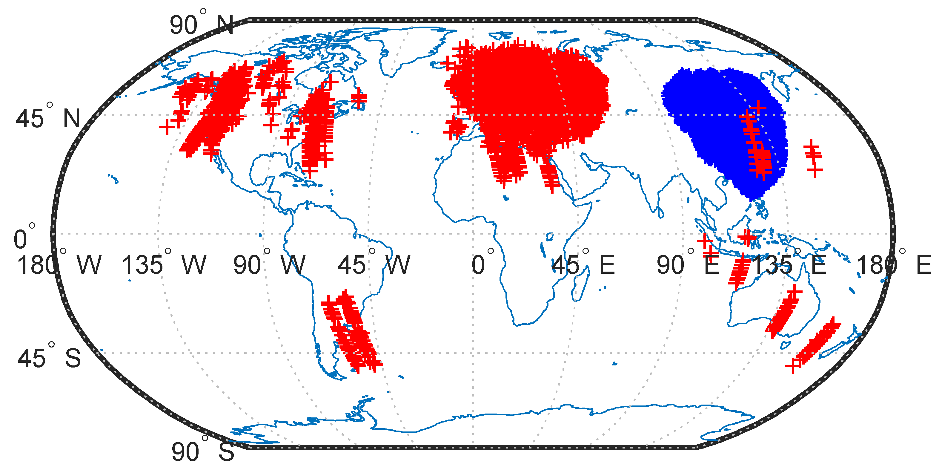
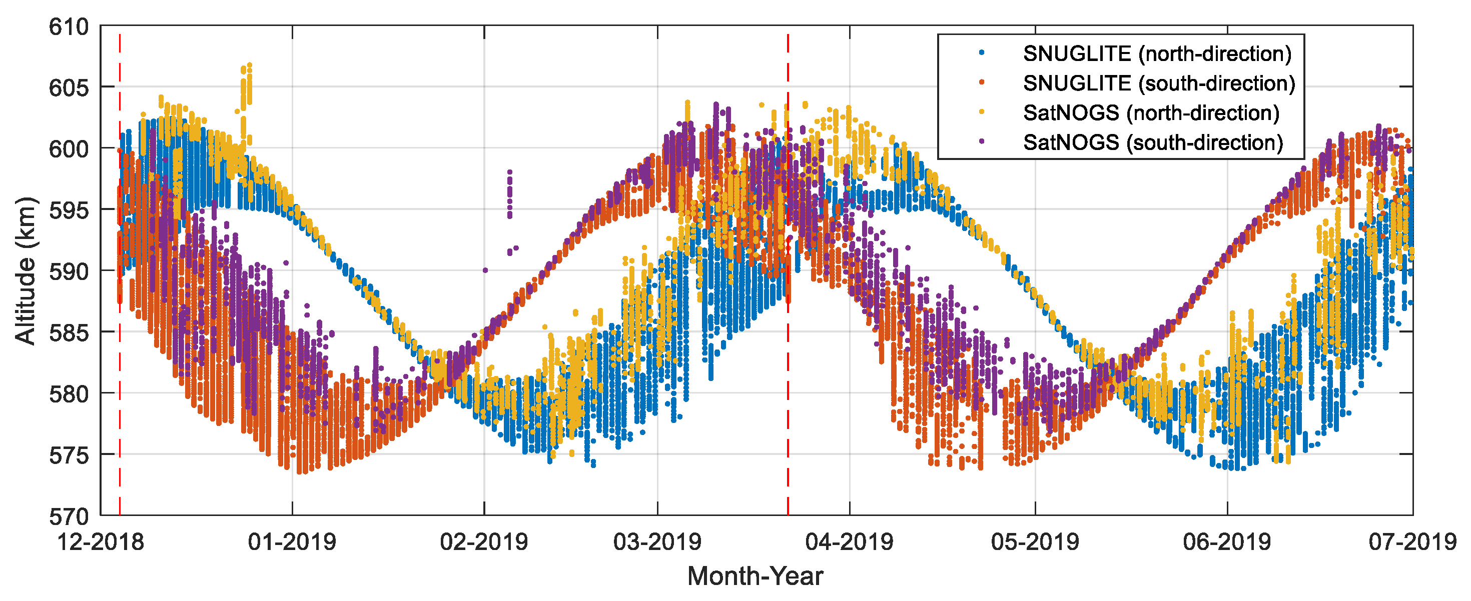
3.1.1. GPS Receiver Results

For the performance analysis of the attitude estimation, the satellite positions were required to generate the reference sun-pointing vector, as shown in Equation (22). This section describes the indicators verifying that the SNUGLITE GPS receivers in orbit are performing normally.
The SNUGLITE CubeSat broadcasts its current position, as calculated by the onboard GPS receiver, every 10 s. Given that the SNUGLITE CubeSat possesses an amateur telecommunication band and uses amateur protocol, the data can be received by any ground stations equipped with conventional amateur equipment. From the launch date until the end of June 2019, a total of 26,400 valid beacons, including GPS position, velocity, and time, have been received. All received GPS positions in latitude and longitude are described in Figure 4. The positioning and velocity results from the SNUGLITE CubeSat were based on the World Geodetic System-84.
It has been confirmed that the SNUGLITE ground station in the Republic of Korea as well as amateur operators in Europe, North and South America, Oceania, and Asia receive signals from the SNUGLITE CubeSat.
One of the methods for evaluating the GPS positioning results is to compare them with the two line element set (TLE) data uploaded from NORAD. The positioning results of the SNUGLITE GPS receiver continuously fit with the orbit generated from TLE parameters up to the km level [18], which is reasonable, because TLE provides rough orbital parameters with km-level accuracy [24]. In addition, positioning accuracy analyses, which use an orbit determination technique that considers orbit dynamics with perturbations, have shown that the root mean square error (RMS) error of the position is less than 5 m [18]. These results are indicators that the GPS receiver in the SNUGLITE has been performing normally.
Altitude results calculated from the GPS receivers in the SNUGLITE CubeSat depict the tendency as described in Figure 5. In Figure 5, ‘SNUGLITE’ indicates the data received at the SNUGLITE CubeSat ground station, and ‘SatNOGS’ indicates the data uploaded to the SatNOGS website [13]. ‘North-direction’ and ‘south-direction’ denote the movement of the satellite from south to north and north to south, respectively. The altitude data are the result obtained when the satellite is located only over the ground station, as described in Figure 4. The altitude varies from 574 to 607 km with a definite period over these regions. The period is caused by the secular motion of perigee, which is also called an apsidal rotation. This secular motion is one of the main effects caused by the first zonal harmonic, which is a J2 by Earth’s oblateness. Furthermore, the fundamental period from zonal harmonics has a large magnitude [25].
The period is theoretically calculated following [25]. Using NORAD’s TLEs, the mean theoretical orbital period was calculated to be 107.92 days, and it is displayed in Figure 5 using red dashed lines.
The period of altitude variation in the figure coincided with the calculated period. The period of altitude variation can be regarded as another indicator to support the healthy operation of SNUGLITE’s GPS receiver.

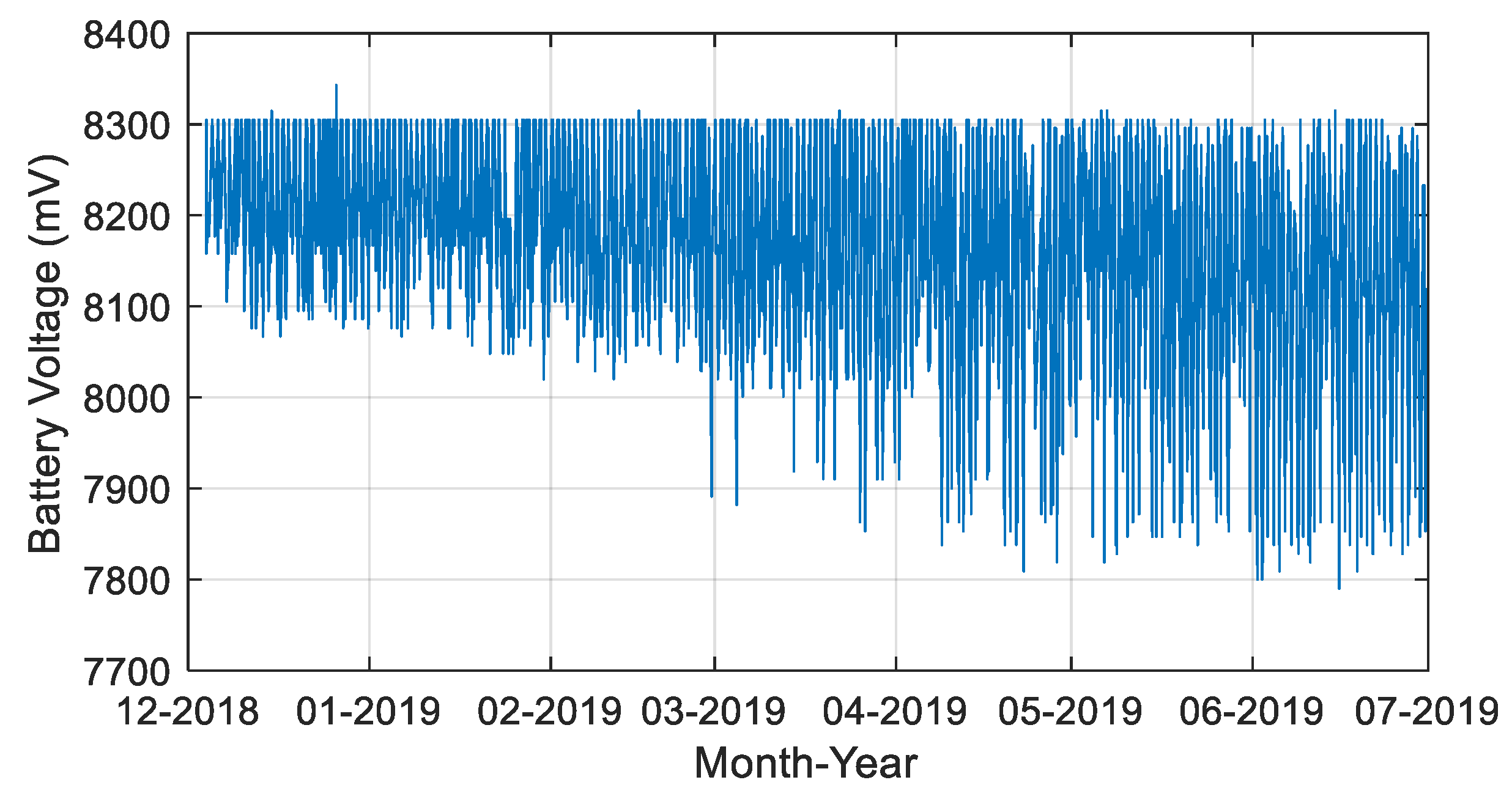
3.1.2. Battery Voltage

The battery voltage of the CubeSat also needs to be considered for the attitude analysis, as there is no power generation when the battery is fully charged. Two lithium-ion 18650 cells were used for the power system of the SNUGLITE CubeSat. The maximum battery voltage was set to 8300 mV. Battery voltage variation from the launch date to the end of June 2019 is described in Figure 6. From March 2019, ground stations have observed a decrease in the battery voltage to under 7900 mV. This decrease has been attributed to the operation of the battery heater.
Figure 6 depicts several full-charge cases, which decreases the number of valid epochs for the attitude analysis because power generation is essential to compute the reference sun-pointing vector, as per Equation (19).

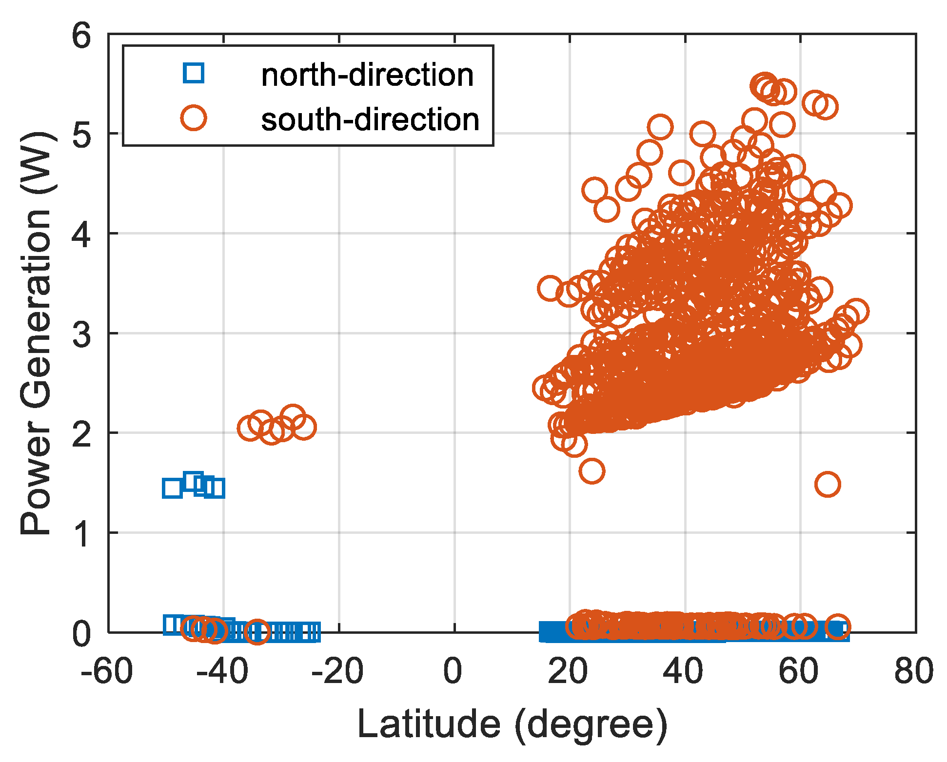
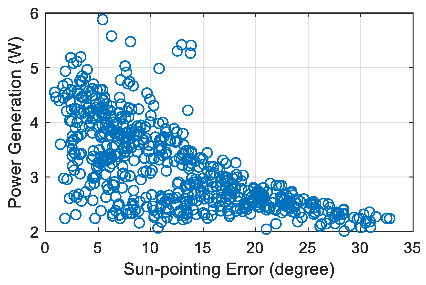
3.1.3. Power Generation

Figure 7 describes the level of power generation according to the latitude in December 2018. We classified the power generations into two groups: north and south directions in orbit. Given that the orbit of the SNUGLITE CubeSat is sun-synchronous, the movements were consistent such that the north and south denote eclipse and daytime, respectively. Since the CubeSat does not use sun-pointing attitude control and the number of solar cells at each surface is different, the power generation changes depending on the CubeSat’s attitude. In addition, the high level of battery voltage also decreases the power generation. When the battery is fully charged, the power generation level is near zero, as described in Figure 7. Though the level of power generation varies, we deduced that the power generation has generally been above 2 W.

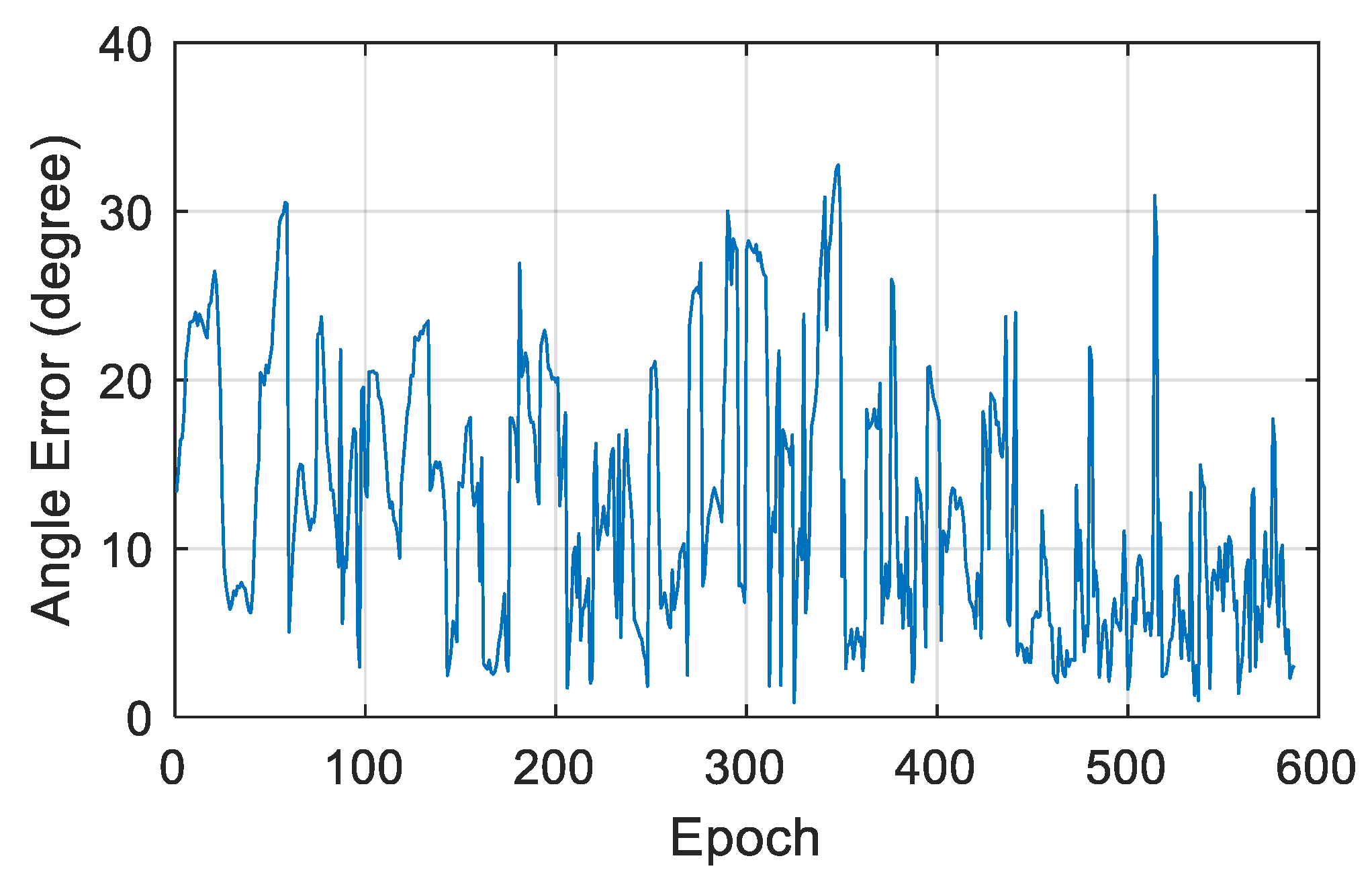
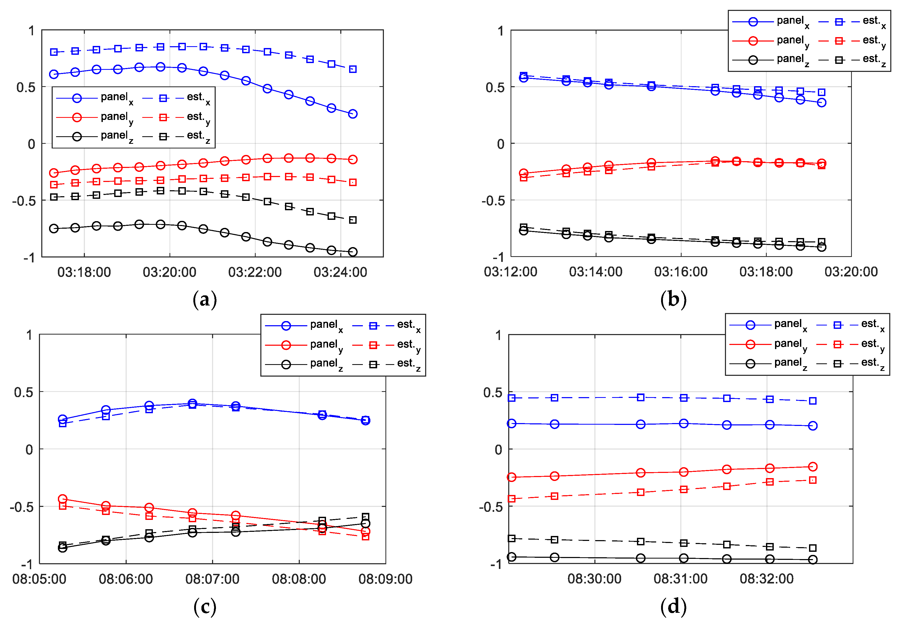
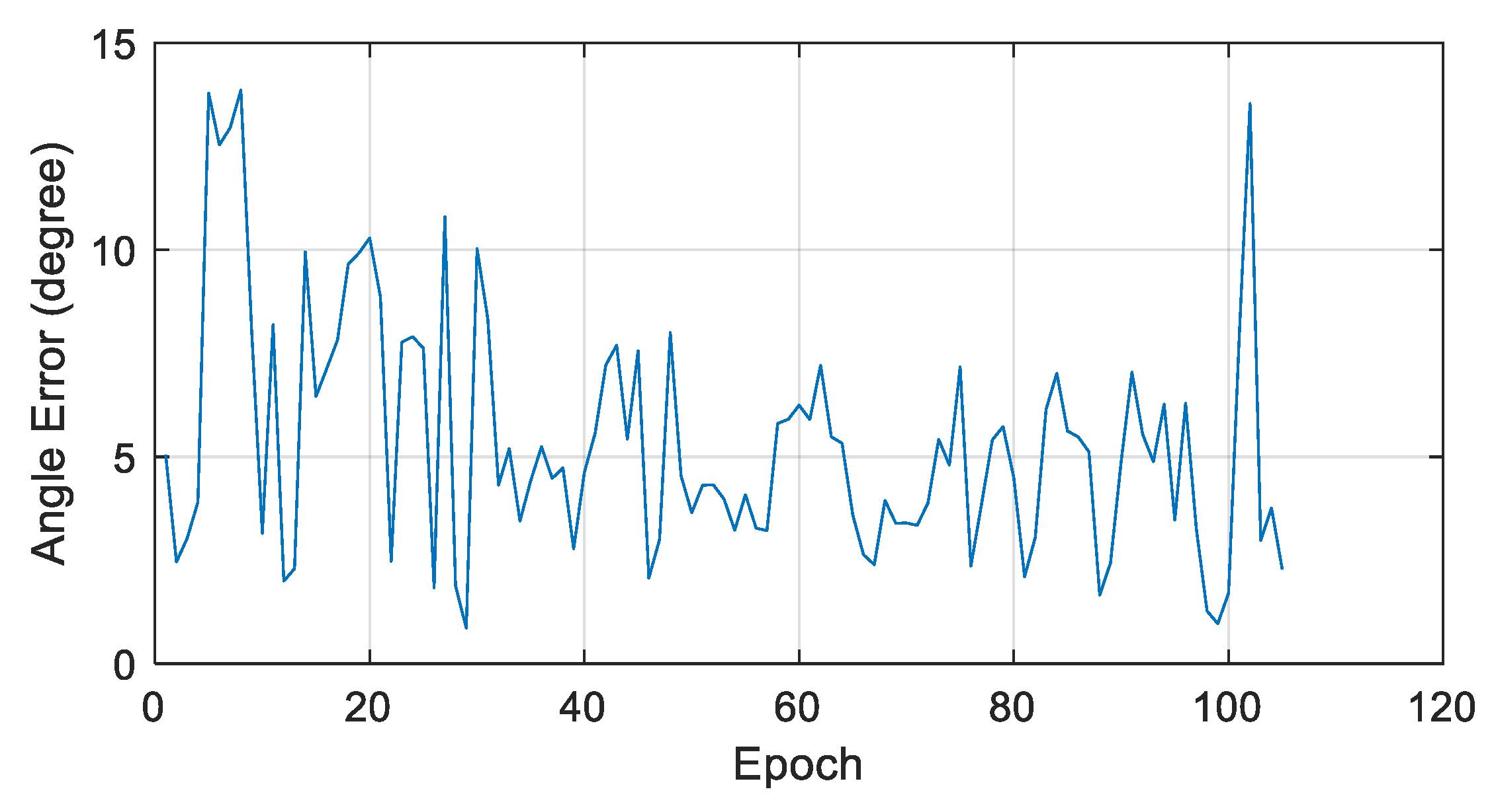
3.2. Satellite Attitude

A performance analysis of attitude estimation was conducted by comparing the two sun-pointing vectors (found using Equation (20)), and the estimated attitude with the vector from the satellite to the sun was calculated using Equation (23). Equations (26) and (27) were utilized to depict the performance of the attitude estimation. During the analysis, Equation (20) was considered as the reference sun-pointing vector. Though the pointing accuracy of the reference sun-pointing vector is somewhat low, it could be used as a rough indicator to verify the operation of the attitude estimation.
Total 8138 full beacons that include information on attitude, temperature, and power generation during 1384 contacts were received between December 2018 and late June 2019. Four conditions needed to be met in order to extract valid epochs for the attitude estimation analysis:
  • The z-component of the GPS velocity in Earth-centered Earth-fixed (ECEF) is negative.
  • The total power generation is more than 2 W.
  • The power generation on the –z side is more than 100 mW.
  • Reverse direction cases of sun-pointing vector by slow temperature changes are excluded.
This type of analysis can be performed only when the satellite is exposed to the sunlight and when power is being generated. According to Figure 7, at least 2 W of power is normally generated during daylight when the battery is not fully charged. According to Figure 6, there are several full-charge cases that decrease the number of valid epochs. Another condition for the daylight is that the z-component of the velocity calculated from the GPS receiver is negative in the ECEF frame. Given that the orbit is sun-synchronous, the negative z-component of velocity indicates that the satellite is moving south during the daytime, and positive cases indicate that it is moving north during eclipse. This decreases the number of valid epochs by half. To use the sun-pointing vector for generating power levels, at least three sides of the solar panels should be exposed to the sunlight. Given that there is no solar panel on the +z side of the SNUGLITE CubeSat, the analysis can be performed only when the –z side is facing the sun. Generating power on the z-axis at more than 100 mW indicates that the –z side is exposed to the sun. In addition, the + or − directions of the x and y axes can be distinguished using the temperatures of each solar panel, as in Equation (19). When the satellite is rotating, however, there is a possibility that the indicated temperature may be that of the reverse side of the radiated panel because temperature changes take time to represent the right direction. These conditions also decrease the number of valid epochs.
The valid number of epochs found by using the above filtering conditions was 587 during 158 contacts, and this was the value used to conduct the attitude analyses. Figure 8 displays the angle error between the two sun-pointing vectors, as per Equation (27), at each valid epoch.
The mean angle error was approximately 12.6°, and the RMS was 14.7°. Figure 9 displays the difference between the two sun-pointing vectors using x, y, and z components for four contact cases. Figure 9b,c display the cases when the attitude estimations were calculated accurately. On the other hand, Figure 9a,d depict the cases where two sun-pointing vectors were biased. However, they displayed similar tendencies.

4. Discussion

A correlation existed between the sun-pointing error and power generation, as described in Figure 10. When there was high power generation, the accuracy of the attitude estimation was improved.
The performances with different power generation levels are described in Table 3. When epochs whose power generation was greater than 4 W were considered, the RMS error of the estimated attitude was at its lowest, at approximately 6.1°.
Utilizing the information currently provided, it was difficult to distinguish which of the sun-pointing vectors of Equations (20) and (23) included error sources. As the power generation on each side of the satellite was considered to generate the reference vector, it was possible that the high power generation cases could make the definitive reference sun-pointing vector with less error. If this is correct, attitude performance analysis using epochs with high power generation capabilities is more reliable. Figure 11 displays the angle error of two sun-pointing vectors at epochs whose power generation was more than 4 W.
The in-orbit real-time attitude estimation performance of the LQG-based attitude system of the SNUGLITE CubeSat was compared and analyzed with previous studies. Because of the lack of studies on the in-orbit performance of the CubeSat platform, there were no cases to present a direct comparison with the SNUGLITE CubeSat’s LQG-based attitude system. For instance, the MinXSS-1 CubeSat achieved high performance attitude estimation, with an accuracy of up to 0.012° (3-σ) [5]. This was possible because of the use of a star tracker, which is very expensive and not suitable for low-cost attitude systems. The performance of a star tracker is in the arc-seconds accuracy level; however, its price is over €30,000 at the time of this publication [26]. The SNUGLITE CubeSat attitude sensors comprises five COTS photodiodes, one MEMS-level three-axis gyroscope, and one three-axis magnetometer, with a total price not exceeding €300. Therefore, the performance comparison of attitude algorithms between these two satellites was inappropriate.
The attitude system of the CSTB1 CubeSat comprises 16 COTS photodiodes sensors and five two-axis magnetometers [6]. Attitude estimation was conducted based on a triad algorithm. The reference-pointing vector for attitude estimation analysis was calculated using an image from the on-board visible camera and the satellite’s position. Since only one sample was considered for the preliminary attitude estimation analysis, with a pointing error was 2.2°, it cannot be considered as a generalized performance. In addition, the attitude of the satellite was calculated based on the sensor data received at the ground receiving station.
The ESTCube-1 CubeSat attitude estimation performance was also evaluated using the on-board camera images [9]. A total 15 images were considered for analysis, which is not sufficient for generalized performance. Its maximum pointing error was 1.43° with unscented Kalman filtering. The ESTCube-1 CubeSat attitude sensor suite includes COTS equipment, two magnetometers, and four gyroscopes, along with six fine sun-sensors, which are superordinate equipment to the photodiode-based sun sensor. The fine sun-sensor can provide a sun-tracking error smaller than 1° (3-σ), but it is not categorized as a low-cost sensor, with a price exceeding €12,000 if six sides of the satellite are fully equipped [26].
Among previous studies, the RAX satellites attitude sensor configuration is the most similar to the attitude sensors of the SNUGLITE CubeSat [8]. RAX-1 and RAX-2 were three-unit CubeSats equipped with two COTS three-axis magnetometers and a three-axis MEMS gyroscope, with different photodiode configurations (9 and 17 photodiodes for RAX-1 and RAX-2, respectively). An extended Kalman filter was considered for attitude estimation. However, the performance of the attitude determination was analyzed by the state error covariance of the filter. Though the RAX CubeSats attitude system performance using the covariance matrix of the filter was below 1.5° (3-σ), it could not represent the actual attitude estimation performance, because a Kalman filter assumes that input errors have a Gaussian distribution [21]. However, there are unexpected biases or disturbances in sensor measurements that increase the actual attitude errors. Instead, attitude analyses need to be evaluated using a reliable performance presented by independent reference sources. Further, the filtering and tuning processes of the RAX CubeSats were conducted offline after the satellite sensor measurements were downloaded.
In general, the in-orbit validations of former attitude systems for the CubeSat platform have limitations, as generalized performances have not been analyzed. In this paper, an attitude estimation analysis of the LQG-based attitude system using low-cost sensors was presented. Generalized performance was achieved by comparing two sun-pointing vectors using independent reference sources with a sufficient number of samples. This methodology can be used in future analyses of attitude systems for the CubeSat platform, particularly for systems using low-cost sensors.

5. Conclusions

The SNUGLITE CubeSat was successfully launched and settled in orbit, and it has since been broadcasting its beacon data continuously. Unfortunately, being that the CubeSat is unable to pick up commands from the ground station, it cannot receive the expected datasets that are excluded from beacon data. Still, though raw data measurements were unavailable, analyses were performed based on the available datasets. Particularly, the results of attitude estimation were verified by evaluating the operation.
In this paper, the novel LQG-based attitude system using low cost sensors and actuators for the CubeSat platform was presented, with focus on the in-orbit real-time attitude estimation performance and analysis using a new method for comparing two sun-pointing vectors. The sun-pointing vector calculated from attitude estimation was compared to the reference sun-pointing vector generated using on-board parameters, such as the power generation levels at each side of the CubeSat. The calculated RMS error between two sun-pointing vectors was approximately 15°, but it reduced to 6.1° for a high power generation situation, which is more reliable.
When the uplink functionality of tele-commands from the ground station to the satellite is restored, SNUGLITE will be able to download continuous raw data, including sensor data and control input for the attitude system, as well as measurements from GPS receivers for scientific missions. This will allow for deep performance analyses of the SNUGLITE CubeSat, including the analysis of the attitude control.

Author Contributions

CubeSat development, O.-J.K., H.S., S.Y., and Y.B.; methodology, C.K. and O.-J.K.; formal analysis and validation, O.-J.K. and H.S.; resources and data curation, Y.B. and S.Y.; writing—original draft preparation, O.-J.K.; writing—review and editing, O.-J.K.; onboard GPS receiver development, H.K., J.L., and J.H.; supervision, C.K.; project administration, S.H. and Y.C. All authors have read and agreed to the published version of the manuscript.

Funding

This research was supported by Basic Science Research Program through the National Research Foundation of Korea (NRF) funded by the Ministry of Science, ICT and Future Planning (No. NRF-2017M1A3A3A02016230), contracted through by the Institute of Advanced Aerospace Technology at Seoul National University. The Institute of Engineering Research at Seoul National University provided research facilities for this work.

Acknowledgments

The authors would like to thank the amateur operators’ efforts to receive the data from the SNUGLITE CubeSat and upload for sharing (https://db.satnogs.org/satellite/43784/). The lists of operators are as below: DK3WN, YC3BVG, SV3CIX, JE9PEL, AD7NP, VK2FAK, EU1XX, UX5UL, JA1GDE, W2RTV, VK3HBF, and CX8AF.

Conflicts of Interest

The authors declare no conflict of interest.

References

  1. California Polytechnic State University. CubeSat Design Specification; California Polytechnic State University: San Luis Obispo, CA, USA, 2013. [Google Scholar]
  2. Emery, W.; Camps, A. Remote Sensing With Small Satellites. In Introduction to Satellite Remote Sensing, 1st ed.; Elsevier: Amsterdam, The Netherlands, 2017; pp. 797–810. [Google Scholar]
  3. Nieto-Peroy, C.; Emami, M.R. CubeSat Mission: From Design to Operation. Appl. Sci. 2019, 9, 3110. [Google Scholar] [CrossRef] [Green Version]
  4. Swartwout, M. CubeSats and Mission Success: 2017 Update. In Proceedings of the Electronic Technology Workshop, NASA Electronic Parts Packaging Program (NEPP) Electron, Greenbelt, MD, USA, 27 June 2017. [Google Scholar]
  5. Mason, J.P.; Baumgart, M.; Rogler, B.; Downs, C.; Williams, M.; Woods, T.N.; Palo, S.; Chamberlin, P.C.; Solomon, S.; Jones, A.; et al. MinXSS-1 CubeSat On-Orbit Pointing and Power Performance. J. Small Satell. 2017, 6, 651–662. [Google Scholar]
  6. Taraba, M.; Rayburn, C.; Tsuda, A.; Macgillivray, C.S. Boeing’s CubeSat TestBed 1 Attitude Determination Design and On-Orbit Experience. In Proceedings of the 23rd Annual AIAA/USU Conference on Small Satellites, Logan, UT, USA, 10–13 August 2009. [Google Scholar]
  7. Springmann, J.C.; Sloboda, A.J.; Klesh, A.T.; Bennett, M.W.; Cutler, J.W. The attitude determination system of the RAX satellite. Acta Astronaut. 2012, 75, 120–135. [Google Scholar] [CrossRef]
  8. Springmann, J.C.; Cutler, J.W. Flight results of a low-cost attitude determination system. Acta Astronaut. 2014, 99, 201–214. [Google Scholar] [CrossRef]
  9. Slavinskis, A.; Ehrpais, H.; Kuuste, H.; Sunter, I.; Viru, J.; Kutt, J.; Kulu, E.; Noorms, M. Flight Results of ESTCube-1 Attitude Determination System. J. Aerosp. Eng. 2016, 29, 04015014. [Google Scholar] [CrossRef] [Green Version]
  10. Boshuizen, C.; Mason, J.; Klupar, P.; Spanhake, S. Results from the Planet Labs Flock Constellation. In Proceedings of the 28th Annual AIAA/USU Conference on Small Satellites, Logan, UT, USA, 2–7 August 2014. [Google Scholar]
  11. Masters, D. Seizing Opportunity: Spire’s CubeSat Constellation of GNSS, AIS, and ADS-B Sensors. In Proceedings of the Stanford PNT Symposium 2018, Stanford, CA, USA, 8 November 2018. [Google Scholar]
  12. Li, J.; Post, M.; Wright, T.; Lee, R. Design of Attitude Control Systems for CubeSat-Class Nanosatellite. J. Control Sci. Eng. 2013, 1–15. [Google Scholar] [CrossRef] [Green Version]
  13. Libre Space Foundation. SatNOGS Database. Available online: https://db.satnogs.org/ (accessed on 30 September 2019).
  14. Gonzalez, O.R.; Kelkar, A.G. Robust Multivariable Control. In The Electrical Engineering Handbook, 1st ed.; Elsevier Academic Press: Burlington, NJ, USA, 2004; pp. 1037–1047. [Google Scholar]
  15. Kim, Y. Attitude Determination and Control of Cubesat Using Magnetic Torquer and LQR Controller. Master’s Thesis, Seoul National University, Seoul, Korea, 2015. [Google Scholar]
  16. Jang, J. Attitude Determination and Control System for Low Earth Orbit CubeSat Considering Operation Scenario. Master’s Thesis, Seoul National University, Seoul, Korea, 2016. [Google Scholar]
  17. Shim, H. HILS Verification of Low Earth Orbit Cube-Satellite Attitude Determination and Control System Using Helmholtz Cage. Master’s Thesis, Seoul National University, Seoul, Korea, 2019. [Google Scholar]
  18. Yu, S.; Kim, O.-J.; Bae, Y.; Shim, H.; Kee, C.; Han, S.; Choi, Y.; Choi, W.-S. Analysis of On-board GPS Receiver Navigation Solutions for SNUGLITE Cubesat. In Proceedings of the KSAS 2019 Spring Conference, Buan, Korea, 18 April 2019. [Google Scholar]
  19. Choi, M.; Yu, S.; Kim, O.-J.; No, H.; Shim, H.; Kee, C. Development and Verification of Attitude Determination and Control Algorithm for SNUGLITE Cube Satellite. In Proceedings of the ITM/PTTI 2018, Reston, VA, USA, 30 January 2018. [Google Scholar]
  20. Choi, M. Sensor Calibration and Single-axis HIL Verification of ADCS for Low Earth Orbit Cube-Satellite. Master’s Thesis, Seoul National University, Seoul, Korea, 2017. [Google Scholar]
  21. Brown, R.G.; Hwang, P.Y.C. The Discrete Kalman Filter, State-Space Modeling, and Simulation. In Introduction to Random Signals and Applied Kalman Filtering, 3rd ed.; John Wiley & Sons: New York, NY, USA, 1997; pp. 190–241. [Google Scholar]
  22. Choi, M.; Jang, J.; Yu, S.; Kim, O.-J.; Shim, H.; Kee, C. Single-axis Hardware in the Loop Experiment Verification of ADCS for Low Earth Orbit Cube-Satellite. JPNT 2017, 6, 195–203. [Google Scholar]
  23. Vallado, D.A.; Seago, J.H.; Seidelmann, P.K. Implementation Issues Surrounding the New IAU Reference Systems for Astrodynamics. In Proceedings of the 16th AAS/AIAA Space Flight Mechanics Conference, Tampa, FL, USA, 22–26 January 2006. [Google Scholar]
  24. Vallado, D.A. Kepler’s Equation and Kepler’s Problem. In Fundamentals of Astrodynamics and Applications, 3rd ed.; Springer: New York, NY, USA, 2007; pp. 49–136. [Google Scholar]
  25. Vallado, D.A. General Perturbation Techniques. In Fundamentals of Astrodynamics and Applications, 3rd ed.; Springer: New York, NY, USA, 2007; pp. 605–724. [Google Scholar]
  26. CubeSatShop by Innovative Solutions in Space. Available online: https://www.cubesatshop.com (accessed on 14 March 2020).
Figure 1. (a) SNUGLITE CubeSat before deployment; (b) SNUGLITE CubeSat after deployment.
Applsci 10 02507 g001
Figure 2. L1/L2C dual-frequency Global Position System (GPS) receiver (2 units) for the CubeSat.
Applsci 10 02507 g002
Figure 3. Block diagram of an linear quadratic Gaussian (LQG)-based attitude system. The image was reproduced with permission from [20].
Applsci 10 02507 g003
Figure 4. Broadcast GPS positions through beacons (blue: received at SNUGLITE ground station; red: received in other ground stations).
Applsci 10 02507 g004
Figure 5. Altitude records calculated by on-board GPS receiver from launch date to late June 2019.
Applsci 10 02507 g005
Figure 6. Battery voltage level.
Applsci 10 02507 g006
Figure 7. Power generation according to the latitude (December 2018).
Applsci 10 02507 g007
Figure 8. Angle error between two sun-pointing vectors.
Applsci 10 02507 g008
Figure 9. Sun-pointing vector comparison: (a) 29th contact on Dec. 11, 2018; (b) 161st contact on Dec. 27, 2018; (c) 518th contact on Feb. 17, 2019; and (d) 657th contact on Mar. 10, 2019.
Applsci 10 02507 g009
Figure 10. Correlation between sun-pointing error and power generation.
Applsci 10 02507 g010
Figure 11. Angle error between two sun-pointing vectors (power generation > 4 W cases).
Applsci 10 02507 g011
Table 1. Specifications of SNUGLITE.
ItemDescription
main payloadsdual-frequency L1/L2C Global Position System (GPS) receiver (2 units)
secondary payloads3-axis flux-gate magnetometer
satellite sizebefore deployment100 × 100 × 227 mm (2U)
after deployment100 × 100 × 727 mm (boom deployment)
satellite weight1.87 kg
satellite communicationfrequencyuplink437.275 MHz 1 (UHF 2)
downlink437.275 MHz 1 (UHF 2)
2405 MHz 1 (S-band)
data rateuplink9600 bps (UHF 2)
downlink9600 bps (UHF 2)
106,000 bps (S-band)
modulationGMSK (UHF 2), DQPSK (S-band)
protocolAX.25 (UHF 2)
orbitsun-synchronous 575 km
1 Amateur radio band; 2 Ultra High Frequency.
Table 2. Full beacon data.
DataDescriptionType
time“YY/MM/DD HH:MM:SS” in UTC (GMT)6 × unsigned char
GPS (Global Positioning System) receiverpositioning flag (“0”: TLE (two line element set), “1”: GPS)unsigned char
“X, Y, Z” position in Earth-centered Earth-fixed (ECEF) (cm)3 × signed int
“X, Y, Z” velocity in ECEF (cm/s)3 × signed int
power systembattery status flag (“0”: initial, “1”: under-voltage, “2”: safe-mode, “3”: nominal, “4”: full)unsigned char
battery voltage (mV)unsigned short
battery current (mA)unsigned short
power-supply-switch flags for each moduleunsigned char
current consumption for each power-supply-switch (mA)6 × unsigned short
solar-panel input voltage: “± X, ±Y, −Z 1” (mV)3 × unsigned short
solar-panel input current: “± X, ±Y, −Z 1” (mA)3 × unsigned short
attitude systemestimated attitude: “q0, q1, q2, q3”4 × float
estimated gyro bias: “roll, pitch, yaw” (rad/s)3 × float
estimated angular rate: “roll, pitch, yaw” (rad/s)3 × float
gyroscope measurements: “roll, pitch, yaw” (rad/s)3 × float
attitude convergence flag and sun/eclipse flagunsigned char
attitude variance: “q0, q1, q2, q3”4 × float
modecurrent operation mode (“0”: init-mode, “1”: standby mode)unsigned char
elapsed time of operation mode (min)signed int
temperaturesolar panels (deg. Celsius)5 1 × unsigned char
onboard computer (deg. Celsius)2 × unsigned char
power module (deg. Celsius)4 × unsigned char
UHF module (deg. Celsius)2 × unsigned char
deployment statusantenna release status flag and boom release status flagunsigned char
number of trial for antenna releaseunsigned char
number of trial for boom releaseunsigned char
1 There is no solar panel for +Z surface (nadir-direction).
Table 3. Attitude estimation performance with different power generation ranges.
Generated PowerNumber of Valid Epoch Angle   Difference   ( δ θ )
Mean (Degree)RMS (Degree)
>2 W58712.614.7
>3 W2877.58.5
>4 W1055.46.1

