1. Introduction
Modern intelligence, surveillance, and reconnaissance systems strongly require to have wide area coverage and high-resolution imaging abilities. High-resolution imaging has often been achieved at the cost of a small field of view (FOV) for current electro-optical and infrared sensors [
1]. In certain imaging applications, such as infrared search and track (IRST) systems, it is desirable for the imaging sensor to scan large fields of regard at a high rate and with diffraction limited performance.
The second-generation IRST systems utilize long line detectors with time delay and integration capability to achieve wide area coverage. However, due to systems limitations of line detectors, the scanning mode of IRST cannot be stopped at any desired position to scan a small sector of interest. They also suffer from more false alarms [
2].
The third-generation IRST systems utilize the FPAs with step/stare imaging to achieve wide area coverage. The new IRST achieves greater performances than the previous generation thanks to their staring nature, i.e., to longer integration times (milliseconds rather than microseconds) [
3,
4,
5,
6,
7,
8]. In step/stare imaging applications, a high-resolution narrow FOV sensor is rapidly stepped or indexed across an area of interest, stopping at intervals to stare and collect imagery. Then the images at each location are stitched together to form a large but high-resolution image. This process requires a series of small angular steps and a high angular acceleration [
9].However, the image motion occurs during the scanning within the exposure time. In order to achieve the line of sight stability, a special optical mechanism has been required to compensate the scanning image motion to achieve the “stare” result when searching and tracking [
10,
11].
Among different technical methods to achieve step/stare imaging, the back-scanning optical compensation technology is the most commonly utilized, in which a plane mirror within the optical system moves reversely to achieve the line of sight stability when searching and tracking [
12,
13,
14,
15,
16]. For example, the camera on the Global Hawk unmanned aerial vehicle utilizes the fast steering mirror (FSM) behind the afocal optics to compensate the scanning image motion. FSMs are utilized to point for line of sight stability in optical systems. With small size, high accuracy, high bandwidth and fast response speed, FSMs are widely applied in electro-optical and infrared sensors [
17,
18,
19].
However, it is frequently assumed that the virtual of a target viewed through a rotating mirror moves with respect to the observer at twice the angular rate of mirror rotation, which is inaccurate and leads to imprecise treatment of open-loop tracking systems. The reason is that the sample of rays reflected from a target to an arbitrary tracker position changes as a function of mirror orientation, and the angle of incidence is not a linear function of mirror orientation, but depends on the relative positions of the target, mirror, and tracker, as well as the orientation of the mirror [
20,
21].Although the equations describing the line-of-sight kinematics derive entirely from the simple plane mirror law of reflection, they are non-linearly- and axis-coupled and these effects increase as the FSM angular displacement increases, which would contribute to pointing errors in certain modes of operation [
9].
As discussed above, the back-scanned step/stare imaging system can scan a large field of regard at a high rate and with diffraction limited performance. However, the traditional optical design forms can hold only one field point relatively stable on the FPA, typically the central or on-axis field point; all other off-axis field points may wander during the exposure time due to image distortion characteristics of the imaging systems, which reduces the SNR of the target. Even though the imaging systems can be designed for high performance imaging and have no distortion when there is no motion, the image wander and image blur for off-axis field points still exist. The amount and significance of the blurring depends on the angular change of the FSM, the angular FOV, and the number of pixels (on the FPA) across the FOV. This problem becomes apparent with the increase of the angle change of FSMs, the increase of the FOV and the decrease of the pixel pitch. Now staring arrays have been fabricated in the mid-wave infrared (MWIR) on the format order of 8 × 8 K with 10 μm pitch [
22,
23,
24]. Long-wave infrared (LWIR) detectors are not as advanced as MWIR detectors, but they are also making significant progress in larger format size and smaller detector pitch [
18]. In this situation, the sensors with super definitions FPAs and long focal length require tight control on the imaging distortion, and even a single pixel shift may cause too much blur for acceptable system performance. Step/stare and IRST systems are widely applied, but this problem of image blurring due to off-axis field point wander is not well recognized and solved.
Therefore, the research objective is to find optimal field mapping between object space and image space, which would make all field points stable on the FPA during back-scanning and the image blurring could be mitigated. At the same time, we want to design a proper optical system that can implement these field mappings. In this manuscript, the mathematical model of non-rotationally symmetric field mapping between object space and image space is established in
Section 2. A design result of back-scanned step/stare imaging system based on this model is designed in
Section 3. Experimental simulation results are analyzed in
Section 4.
2. Mathematical Model for Back-Scanned Step/Stare Imaging System
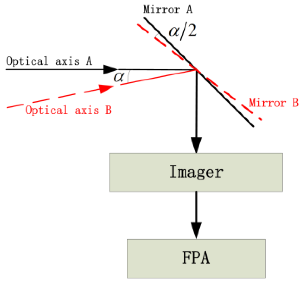
Figure 1 is a principle schematic diagram of utilizing the plane mirror to achieve the line of sight stability. It is assumed that the optical axis and the mirror are in the state A at the beginning of the exposure of the FPA. At this time, the light beam from the infinity object point on the optical axis is turned 90 degrees by the plane mirror, and then focused on the center of the FPA by the imager. During the exposure process, with the movement of the platform, the optical axis changes to the state B. The angle between the original optical axis A and the current optical axis B is α. By turning the mirror to the state B, the angle between the mirror A and the mirror B is α/2. The light beam from the infinity object point on the optical axis is turned by the mirror, and then still focused on the center of the FPA by the imager. The change of the optical axis is compensated by the change of the angle of the mirror. During the integration time of the FPA, the light beam from the infinity object point on the optical axis is always focused on the center of the FPA.
During the rotation of the mirror, projection distortion is produced in the image plane due to the change of the optical axis. This projection distortion makes off-axis field points wander during the exposure time, which reduces the SNR of the target. In the following, we want to find optimal field mapping between object space and image space, which would make all field points stable on the FPA during back-scanning and the image blurring could be mitigated.
It is assumed that the relationship among the image height, the focal length of the imager and the incident angle of the imaging system in
Figure 1 can be expressed by Equation (1):
where
is the image height,
is the focal length of the imager,
is the angle between the incident light and the optical axis.
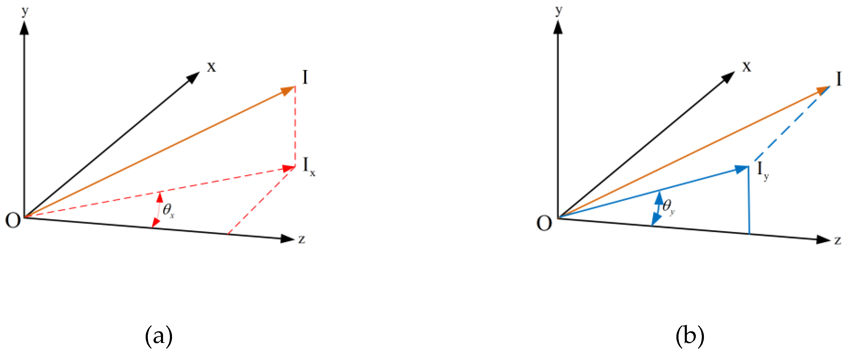
In
Figure 2, the FOVs in object space are conventionally defined for optics, based on the x-y-z coordinate system.
When the optical axis is in the state A, the image point coordinates of the chief ray
on the FPA are shown in Equation (2),
where
is the image height in x direction,
is the image height in y direction.
Considering that y-direction of the FOV is the scanning direction. When the change angle of the optical axis is
and the mirror rotates
, the image point coordinates
of the chief ray
on the FPA will come to be expressed by Equation (3):
Calculating the difference between image points
and
in Equation (4),
it can be seen that the position of the image point of the chief ray
changes during back-scanning.
It is assumed that the relationship among the image height, the focal length of the imager and the incident angle of the imaging system in
Figure 1 is shown in Equation (5):
When the optical axis is in the state A, the image point coordinates of the chief ray
on the FPA are expressed by Equation (6):
Considering that y-direction of the FOV is the scanning direction. When the change angle of the optical axis is
and the mirror rotates
, the image point coordinates
of the chief ray
on the FPA will come to be expressed by Equation (7):
Calculating the difference between image points
and
in Equation (8),
it can be seen that for the line field of view
, the image wander is zero at different angles
. For the condition of
and
, the image wander always exists during scanning.
The existence of projection distortion is because the optical axis of the imaging system is changed by the angle
, but
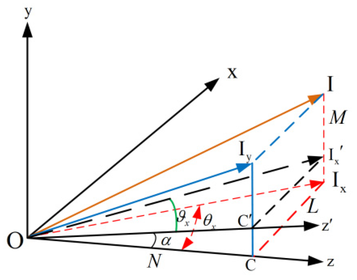
is still based on the original optical axis.
Figure 3 shows a schematic diagram of the new projection relationship. Where
is the original optical axis. When the optical axis is in the state B,
, the new optical axis changes to
. The projection point of
on the original optical axis
is
. The intersection of
and the new optical axis is
.
is parallel to
.
The angle between
and the new optical axis
is
, and we define
as the field angle in the x direction.
are the direction cosines of
in the original optical axis coordinate system.
Using Equation (9), we can get the Equation (10):
It is assumed that the relationship among the image height, the focal length of the imager and the incident angle of the imaging system in
Figure 1 is shown in Equation (11):
Considering that y-direction of the FOV is the scanning direction. When the change angle of the optical axis is
and the mirror rotates
, the image point coordinates
of the chief ray
on the FPA will come to be expressed by Equation (12):
Calculating the difference between image points
and
in Equation (13),
it can be seen that the image wander caused by the projection distortion during the scanning of the mirror is zero.
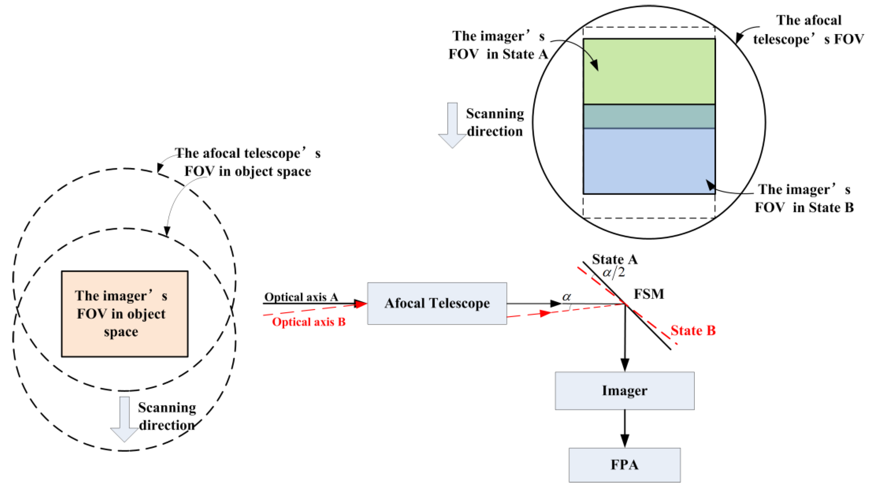
When the FSM is put in the middle of the optical system, an imaging system is schematically shown in
Figure 4, which includes a front-end afocal telescope, a FSM, an imager and an FPA. Back-scanning with a FSM behind the afocal telescope provides an agile method to increase the integration time for the FPA by compensating for movement of the imaging system. As the system scans in object space, the FSM tilts to attempt to keep the image fixed on the FPA during the integration time. In
Figure 4, the imager’s FOV is scanned through the afocal telescope’s FOV. The green box represents the imager’s FOV at the earlier point in State A. The blue box represents the imager’s FOV at the later point in State B. The black circle represents the afocal telescope’s FOV. The gray arrow represents the scanning direction. The corresponding back-scanned imager’s FOV in object space are also showed. The afocal telescope’s FOV is scanning to the down, while the FSM moves to keep the imager’s FOV (the orange box) fixed during the integration time.
Assuming that the angular magnification of the afocal telescope is
and the focal length of the imager is
, in order to meet Equation (14), the following conditions should be satisfied:
At this time, the relationship of the imager can satisfy
, but the afocal telescope needs to satisfy the following relationship in Equation (15):
Modifying Equation (11), we can get the Equation (16):
The power series expansion to
can be obtained in Equation (17):
Unlike the conventional field mapping of equation and , the optimal field mapping according to Equations are not rotationally symmetric. It has an anamorphic nature. This non-rotationally symmetric field mapping deletes all field points wander during back-scanning.
3. Optical System Design
The mathematical model of non-rotationally symmetric field mapping between object space and image space is established in
Section 2. In this section, we want to design optical system which can implement these field mappings.
The design specifications are shown in
Table 1. The spectral band is 3.7–4.8 μm (medium-wave infrared). The focal length of the optical system is 500 mm. The F-number of the optical system is 4. The detector is a two-dimensional FPA having 1280 × 1024 pixels. The pixel pitch of the FPA is 15 μm. The magnification of the afocal telescope is 5×. The FOV of the frame is 2.2 × 1.76 degrees. The scanning speed of optical system is 40 deg/s and the normal integration time is 10ms. Consequently, the back-scan is over ±0.4 degrees in object space, and then the FOV of the afocal telescope is 2.2 × 2.56 degrees.
It should be noted that the main purpose of this manuscript is to explain the image points wander during back-scanning. In order to simplify the design, the imager is set as an ideal lens, and the practical problems of infrared optical system design such as secondary imaging and cold stop matching are not considered.
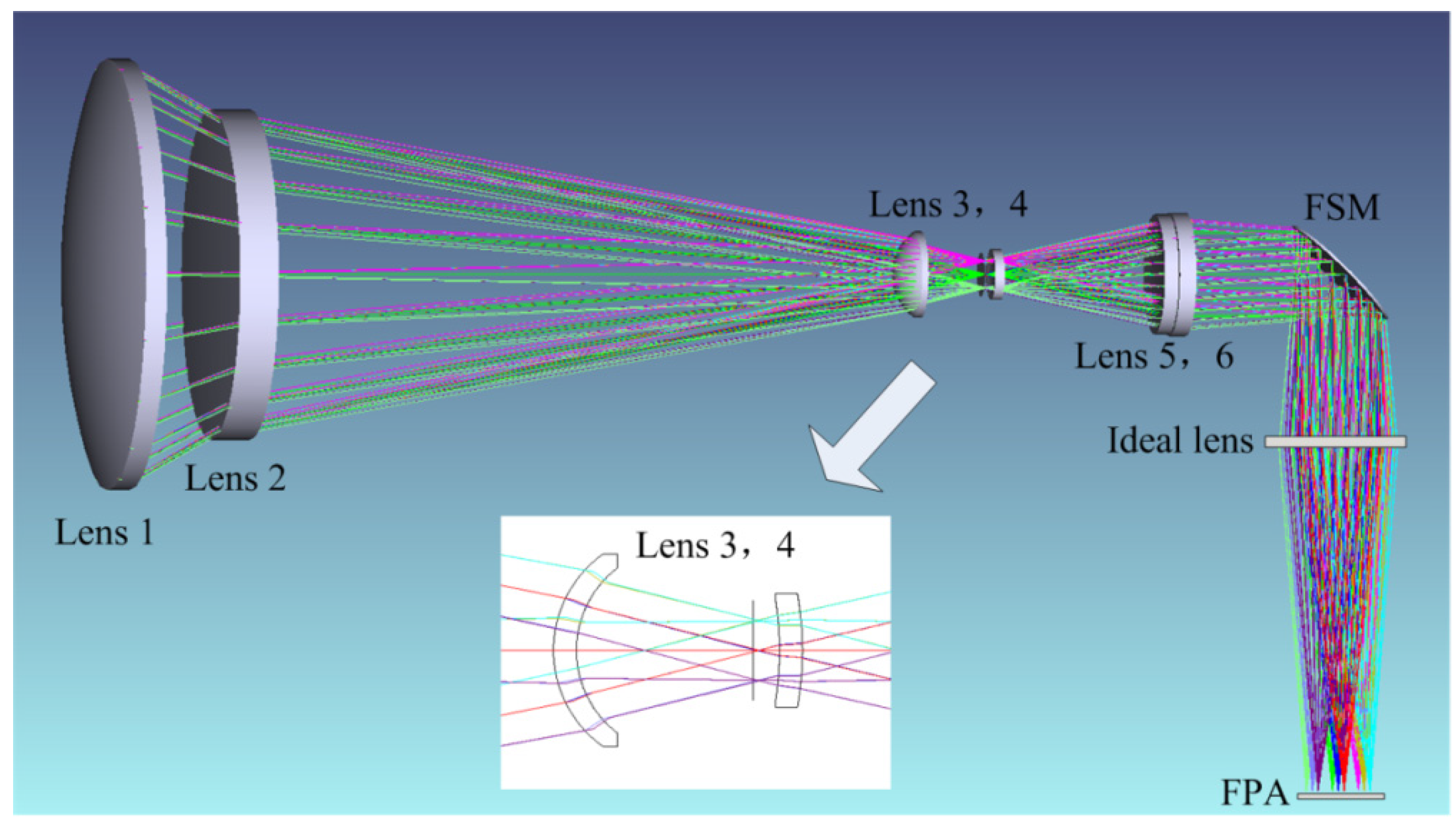
The optical system designed according to the field mapping condition
is shown in
Figure 5. The afocal telescope is consisted of six lenses. From left to right, the lens 1, the lens 3, the lens 4, and the lens 5 are made of silicon and have a positive power. The lens 2 and the lens 6 are made of germanium and have a negative power. The entrance pupil is placed on the front surface of the lens 1. The rear surface of the lens 2 is a quadratic aspherical surface. The lenses 3 and 4 are field lenses, and have a small power. The rear surface of the lens 3 and the front surface of the lens 4 are freeform surfaces. The remaining surfaces are spherical. The FSM is placed on the exit pupil of the afocal telescope, and the optical axis is turned by 90 degrees. The ideal lens imager focuses the scene onto the FPA.
The freeform surfaces used in this example are extended XY polynomial. The sagittal deviation
between the freeform surface and the standard spherical surface is expressed by Equation (18):
The above non-rotationally symmetric freeform surfaces are used to control the tilt of the chief ray in the X and Y directions, which can produce an anamorphic aberration to meet the Equation (11).
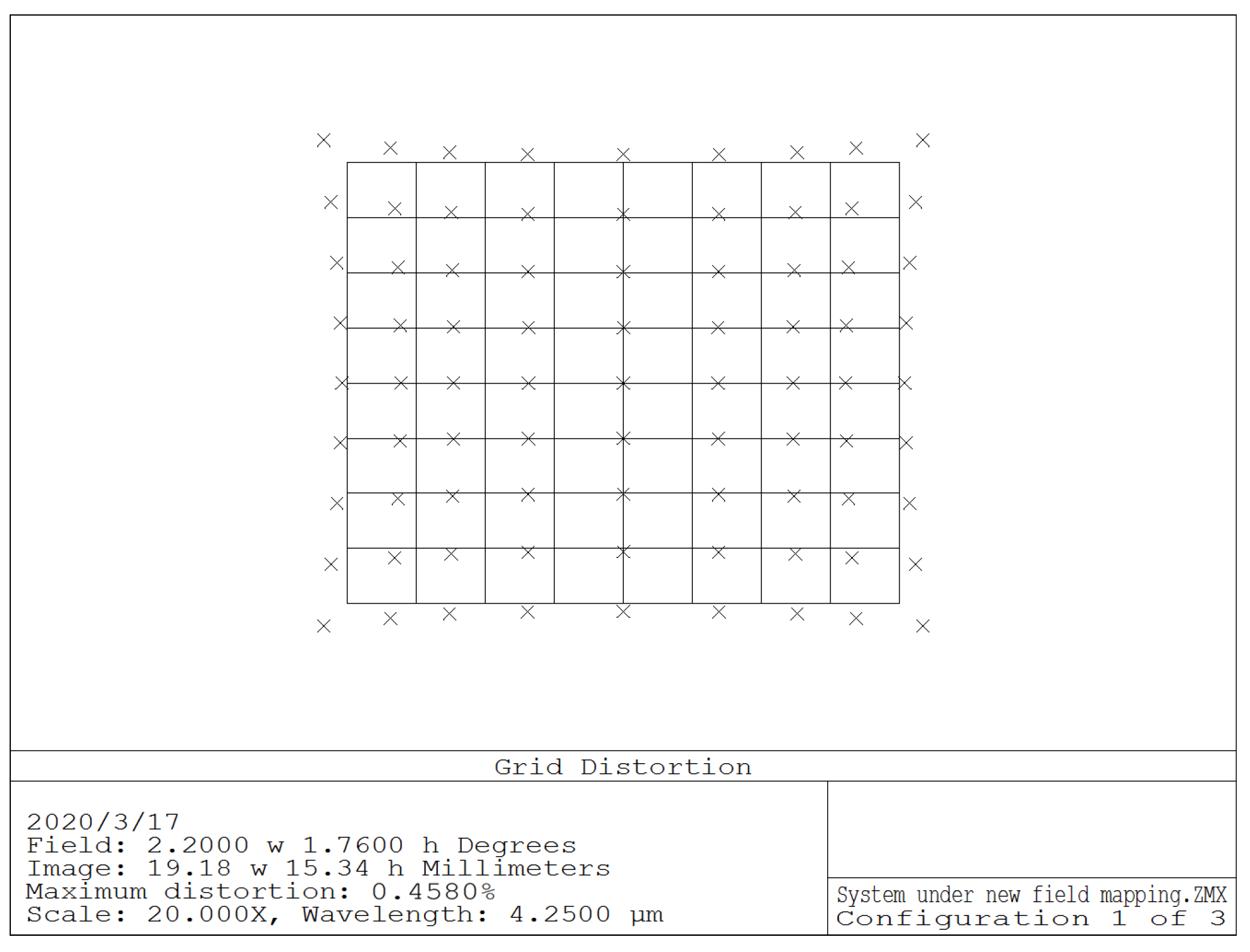
A special macro is coding to constrain the relationship among the image height, the focal length and the incident angle of the imaging system to meet Equation (11). At the same time, a multi-configuration is designed to include five different angles of the FSM. In the process of optimization, the image heights of the same FOV are limited to be equal. If this new field mapping is strictly restricted, the image quality of the system will be degraded, and the image distortion will be very serious. For the actual optical systems design, it is necessary to balance aberrations to meet the special specifications, such as the maximum allowable distortion when the FSM does not move, the maximum image wander during back-scanning and the minimum MTF under the Nyquist frequency. For the above optical system, the distortion weight should be magnified as much as possible while the MTF is close to the diffraction limit. For this optical system, the maximum distortion is less than 0.46% within the FPA.
Figure 6 shows the grid distortion map. In order to visualize the distortion characteristics, the distortion deviation is enlarged by 20 times. As can be seen from
Figure 6, the distortion is similar to pincushion distortion, but the distortion is not rotationally symmetric. The deviation of the actual image with the theoretical field point in
x direction is larger than that in
y direction.
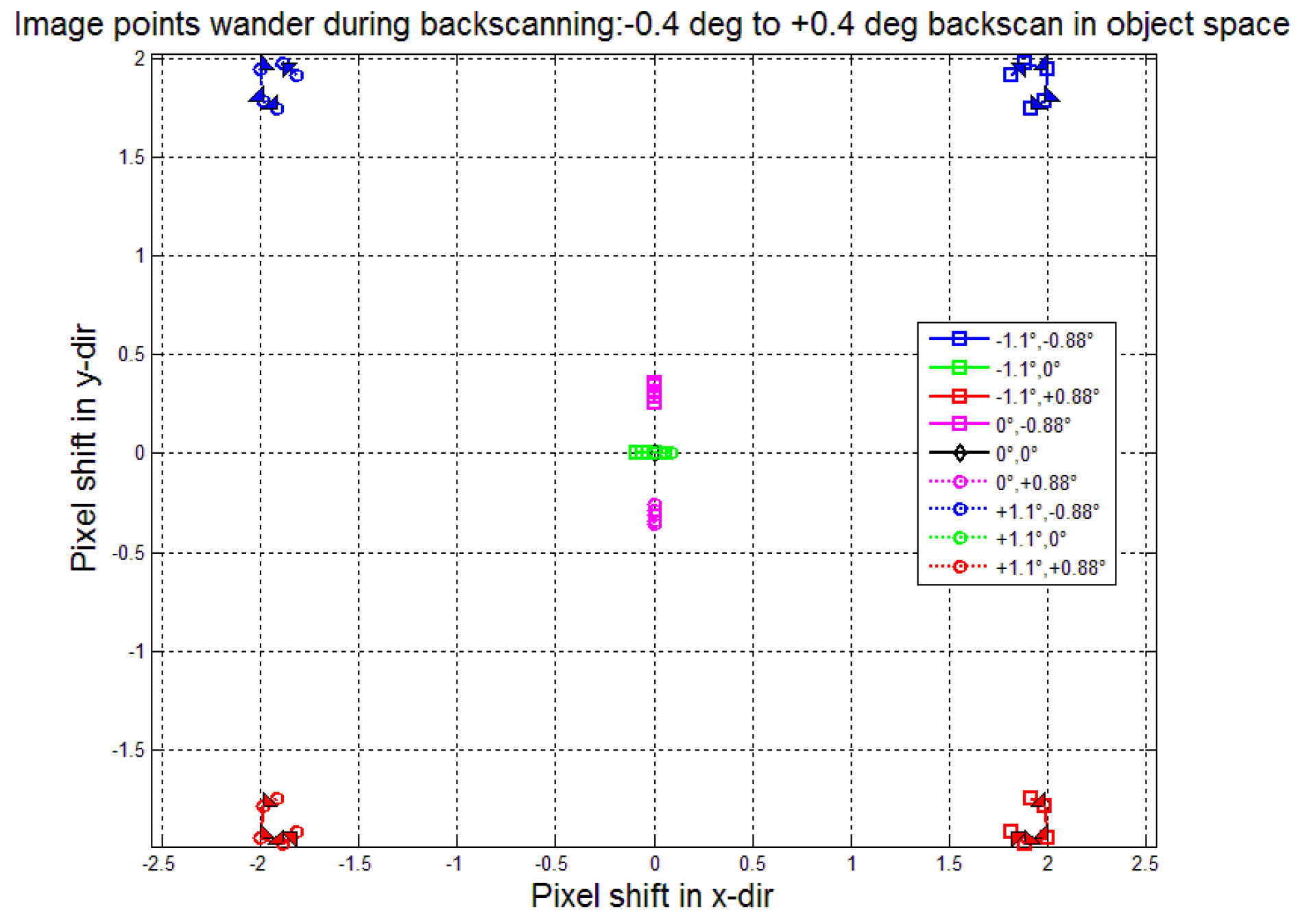
During the exposure of the FPA, the back-scan is over ±0.4 deg in object space. The curves in
Figure 7 indicate motion (in units of pixel IFOV) of the chief ray at nine image points during the back-scan operation. As we can see in
Figure 7, except for the central image point, the other off-axis image points have image wander. The image wander at the four edge fields of view is the largest. Compared with the case when the fast steering mirror has no motion, the maximum image blur during the back-scan is only 0.22 pixels. The image point motion caused by projection distortion is well controlled.
4. Comparison and Analysis
In order to explain the distortion characteristic differences of optical systems under different field mapping equations during back-scanning, another two medium-wave infrared optical systems are successfully designed in meeting the same design specifications in
Table 1.
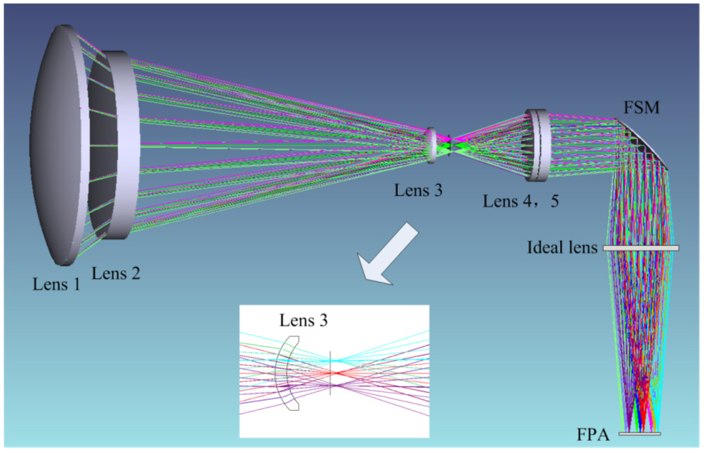
The optical system designed by Zemax software according to the field mapping condition
is shown in
Figure 8. The afocal telescope is composed of five lenses. From left to right, the lens 1, the lens 3, and the lens 4 are made of silicon and have a positive power. The lens 2 and the lens 5 are made of germanium and have a negative power. The entrance pupil is placed on the front surface of the lens 1. The rear surface of the lens 2 is a secondary aspheric surface, and the remaining surfaces are spherical. The lens 3 is a field lens, and the optical power is very small. The fast steering mirror is placed on the exit pupil of the afocal telescope, and the optical axis is turned by 90 degrees. The imager focuses the scene onto the FPA. The optical system have good imaging performance and low pupil aberrations.
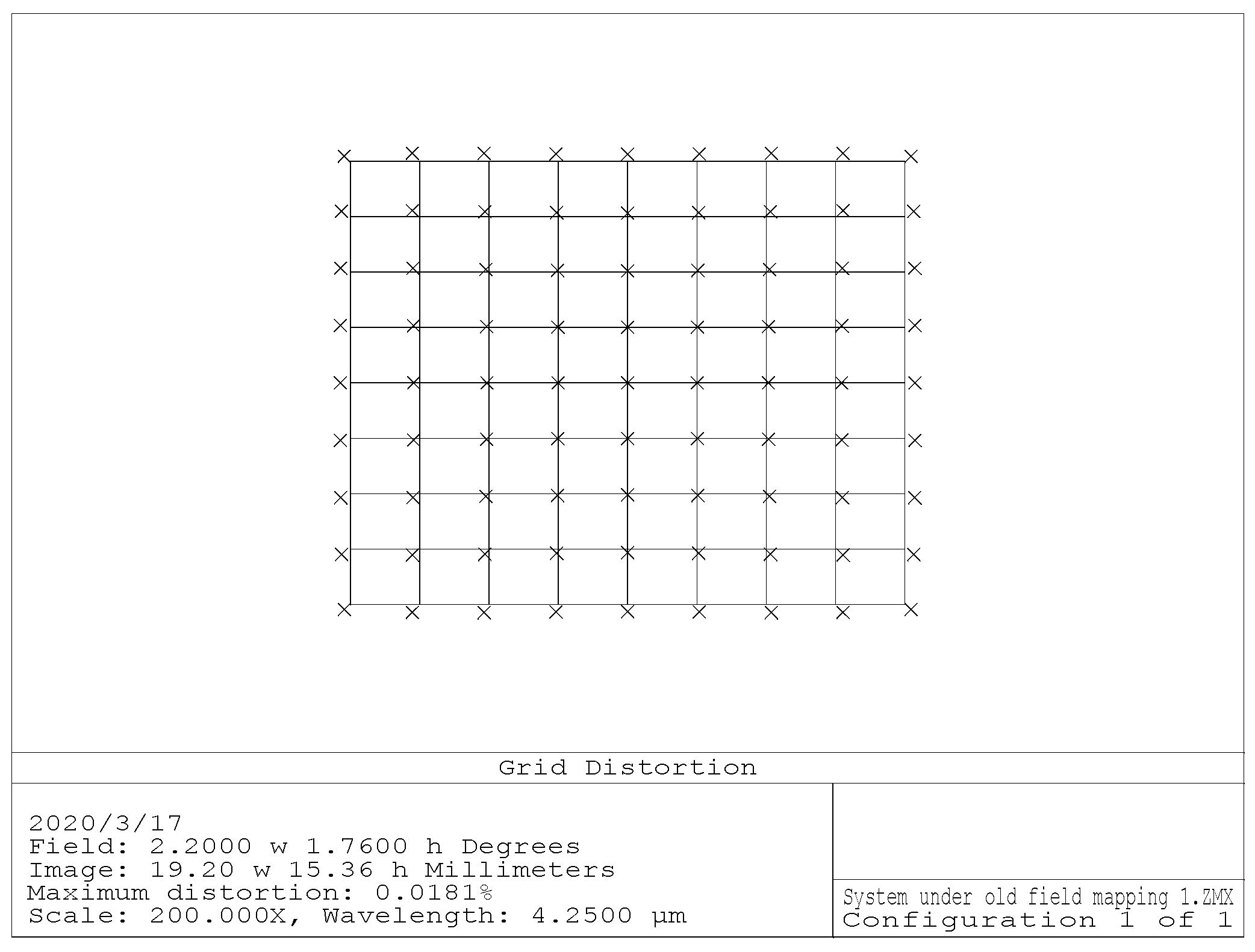
The optimization commands of Zemax software are utilized to set the relationship among the image height, the focal length and the incident angle of the imaging system to meet Equation (2). For the above system, the MTF is close to the diffraction limit. The maximum distortion is less than 0.02% within the FPA. When FSM remain still, the distortion of the optical system is controlled well.
Figure 9 shows the grid distortion map. In order to visualize the distortion characteristics, the distortion deviation is enlarged by 200 times. As can be seen from the figure, this optical system displays symmetrical barrel distortion. In this moment, the distortion seemed to be controlled and the image quality seemed to be well. Further, the FSM placed behind the afocal telescope could be considered to have nothing to do with the image quality by optical designers. Actually, the movement required to track an image viewed through a rotating mirror is a nonlinear function of the mirror movement, but this fact is always neglected [
20].
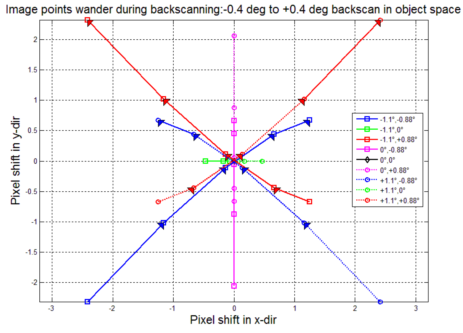
During the exposure of the FPA, the back-scan is over ±0.4 deg in object space. The lines in
Figure 10 indicate motion (in units of pixel IFOV) of the chief ray at nine image points during the back-scan operation. As can be seen from the figure, except for the central image point, the other off-axis image points have image wander. The image wander at the four edge fields of view is the largest. Compared with the case when the fast mirror has no motion, the maximum distortion image shift is 3.13 pixels. This image wander will severely degrade the image quality.
The optical system in
Figure 8 is optimized according to the condition
. Only the lens radius, air distance, and aspheric coefficient are slightly different, and the rest remain the same. The optimization commands of Zemax software are utilized to set the relationship among the image height, the focal length and the incident angle of the imaging system to meet Equation (6). For the above system, the MTF is close to the diffraction limit. For this optical system, the maximum distortion is less than 0.012% within the FPA. When fast steering mirror does not move, the distortion of the optical system is controlled well.
Figure 11 shows the grid distortion map. In order to visualize the distortion characteristics, the distortion deviation is enlarged by 200 times. As can be seen from the figure, this optical system still displays symmetrical barrel distortion. The field mapping of Equation (6) minimizes image wander for field points along a single axis. Line-scan systems can use this mapping and achieve adequate results. However, this optimal one-dimensional field mapping is not ideal for two-dimensional imaging systems.
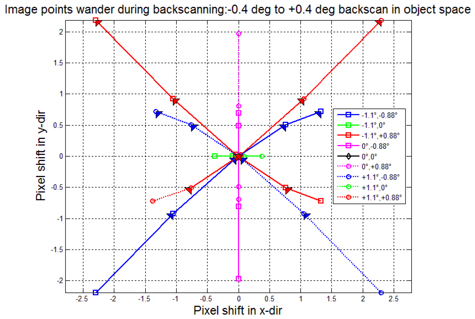
During the exposure of the FPA, the back-scan is over ±0.4 deg in object space. The lines in
Figure 12 indicate motion (in units of pixel IFOV) of the chief ray at nine image points during the back-scan operation. As can be seen from the figure, except for the central image point, the other off-axis image points have image wander. The image wander at the four edge fields of view is the largest. Compared with the case when the fast mirror has no motion, the maximum distortion image shift is 3.18 pixels. The image wander is similar to that in
Figure 12. This image wander will also severely degrade the image quality.
Additionally, we compared the optical system based on the proposed model
to the optical systems based on the model
and
in our experiments, and the distortion and image wander are selected as the evaluation parameters.
Table 2 lists the maximum distortion when the FSM does not move and the maximum image point wander during back-scanning in the previous three optical systems. The optical systems that meet
and
have a distortion of less than 0.02%, which is approximately no distortion. At this time, the movement of the image points are caused by the projection distortion during the movement of the FSM. For the optical system that meets the conditions of non-rotational projection, the maximum distortion is less than 0.46%. When the FSM does not move, a large distortion remains in the optical system, which is more than 23 times that of the conventional optical systems. During the rotation of the FSM, the maximum wander of the image points on the FPA is only 0.22 pixels, and the remaining distortion just compensates for the projection distortion, which verifies the effectiveness of the proposed method, as "one cannot make an omelet without breaking eggs". However, in order to achieve no image point wander during the back-scanning, the optical system is more complicated than the traditional optical systems, and non-rotationally symmetric free-form surfaces are required to achieve a non-rotational symmetry field mapping.


