Article

Analysis of Volume Distribution and Evaluation of the Spraying Spectrum in Terms of Spraying Quality

Warsaw University of Technology, Faculty of Civil Engineering, Mechanics and Petrochemistry, Institute of Mechanical Engineering, Lukasiewicza 17, 09-400 Plock, Poland
*
Author to whom correspondence should be addressed.
Appl. Sci. 2020, 10(7), 2395; https://doi.org/10.3390/app10072395
Submission received: 2 March 2020 / Revised: 25 March 2020 / Accepted: 27 March 2020 / Published: 1 April 2020
(This article belongs to the Section Environmental Sciences)

Abstract

:
Assessment of the quality of the operation of agricultural nozzles on the basis of transverse volume distribution and spatial methods of analysis for stream spraying spectra is insufficient, and positive result do not guarantee that the intended and effective spraying effects are obtained. Tests were carried out to assess the quality of nozzles on the basis of transverse volume distribution analysis, microstructure characteristics, and detailed analysis of places where an unexpected change in the nature of the transverse volume distribution (increase in volume) was noted. The subjects of the study were RS11003 flat fan nozzles and a measuring stand equipped with a grooved table, which was used to carry out tests. During the tests, the unit flow rate from the nozzles, the transverse volume distribution of liquids from individual table grooves, and the corresponding CV distribution coefficients of variation were recorded. Detailed tests were carried out for the selected nozzle, consisting of spot measurement of droplet characteristics in individual liquid stream bands. The widths of these bands were constant and equal to the width of the measuring table groove. Measurements were made using analyzer 2D-Laser Doppler Anemometry/Phase Doppler Anemometry (2D-LDA/PDA) from Dantec Dynamics. The analysis of the results obtained from the grooved table and the droplet characteristics in individual stream bands showed clear and unexpected changes in the nature of the transverse volume distribution for all tested nozzles. These changes, consisting of a local increases in droplet diameters (with a reduced number of occurrences), can cause a significant reduction in the quality and effectiveness of spraying, despite the positive fulfillment of generalized normative criteria for their assessment.

1. Introduction

There is no doubt that the droplet size spectra produced by different nozzle types (e.g., air induction or conventional) [1] and also by liquid atomization (e.g., hydraulic or pneumatic) [2] affect the efficiency of spray application and the efficacy of chemical plant protection products (PPP). An efficient spray application is the main strategy to simultaneously increase the benefits of PPP, reduce the risk of environmental and human contamination, and produce high-quality and safe food in a sustainable way [3,4]. Therefore, the efficiency of spray applications depends primarily on the proper functioning of the nozzles and on the work parameters selected [5,6]. Conventional flat fan nozzles, characterized by hydraulic atomization, are the most commonly used in spraying of arable field crops [6,7,8] and for herbicide applications in 3D crops [9,10]. The selection of nozzle type according to the needs of the treatment specifications should aim to achieve the required total application volume rate, taking into account the spray quality [11], to both maximize the efficacy of treatments and minimize the drift risk. The PPP label recommendations should also be taken into account to select the best working parameters. The assessment of the work performance agricultural nozzles is based on the testing macro- and microparameters of the atomized liquid. The most important of these parameters are the unit flow rate and the uniformity of the transverse volume distribution, characterized by the CV coefficient. Another important criterion is also the qualification of the nozzle for the appropriate droplet class (spectrum of droplets produced) according to ANSI/ASAE S572.1 in terms of volume diameters Dv0.1, Dv0.5 (VMD), and Dv0.9 (μm) [12,13]. The acceptable values of the listed parameters and criteria for assessing the operation of nozzles are: tolerance of the unit flow rate (±5%) of the nominal value according to ISO 10625-2005 [14]; CV, with a maximum allowable value of 10% (ISO 5682-1-1996) [15]; and the droplet spectrum, ranging from extra-fine (XF) to ultra-coarse (UC), according to ANSI/ASAE S572.1, 2009. Therefore, the effectiveness of the application process of plant protection products is influenced by the spraying characteristics, which depend, among others, on the droplet size distribution, the nature of the volume distribution, and the spraying structure [16], which determines how well the plants are covered with working liquid [17]. From the above, various consequences arise regarding the spray quality of the utility liquid and the optimal droplet sizes [16,17,18]. The suitability of individual droplet fractions, and thus the efficiency and effectiveness of the chemical application, depends on their intended use (fungicide, herbicide, insecticide, etc.) and the conditions of use [19]. The droplet fraction (class) produced by the nozzle is given by its manufacturer, together with the nominal unit flow rate and the CV coefficient value. The listed parameters usually fall within their allowable values, which is confirmed by the results of numerous tests. However, the authors would like to draw attention to the fact that there may be significant local deviations of the droplet fraction (with an unknown mechanism of formation), which in many cases cause negative consequences related to the quality and effectiveness of the procedure. Such diversity of the droplet spectrum in the spray liquid stream (droplet sizes and their number of occurrences) causes an unfavorable volume distribution, which negatively affects the coverage uniformity of the sprayed surface [20]. Analysis of the spectrum characteristics for the entire stream, especially when spatial measurement methods are used to obtain them, may not reflect this significant variation in the droplet spectrum in individual stream bands. This fact is the genesis of undertaking research in the field of spraying spectra assessment in selected liquid stream bands using the laser Doppler anemometry method. For this purpose, an analyzer 2D-Laser Doppler Anemometry/Phase Doppler Anemometry (2D-LDA/PDA) from Dantec Dynamics was used, which allows point measurement of the droplet spectrum. The aim of the study was to assess the spraying spectrum of a liquid stream and its impact on the nature of volume distribution in terms of spray quality on the example of the selected flat fan spray nozzles.

2. Materials and Methods

The subjects of the research were new standard flat fan nozzles RS11003 from the MMAT Agro Technology, Leszno, Poland. Seven copies were randomly selected from a batch of 75 pieces. According to the manufacturer’s data, the nozzle produces a droplet spectrum ranging from fine to medium droplets with regard to ANSI/ASAE S572.1, 2009. The optimum fraction of the droplets produced is 100–250 µm. Due to the reduction of the risk of drift of the finest droplet fraction (<100 µm), it is recommended to use nozzles in the following conditions: wind speed up to 2 m/s, temperature 12–20 °C and relative humidity above 60%, maximum pressure range 1.5–5 bar [21]. Certification tests for this group of nozzles were carried out for a pressure of 3 bar, as a result of the tests obtaining a unit flow rate of 1.15 dm3/min, spray angle α of 103°, and a coefficient of uniformity of the transverse volume distribution (characterized by CV coefficient) of 7.6%.
In the first stage of research, the nozzle quality was assessed based on the results of the lateral uniformity of volume distribution, characterized by the CV coefficient. Seven samples of the RS11003 nozzles and the reference TP11003-SS nozzle from TeeJet were used in the tests. The CV coefficient was determined based on the results of measurements of liquid volume distribution on a standardized groove table with a groove width of 25 mm, carried out in accordance with ISO 5682-1-1996 standards and applicable nozzle inspection procedures [15]. The stand used to test the lateral uniformity of volume distribution is shown in Figure 1 [22].
Laboratory tests were carried out for the following parameters and accepted conditions:
  • The working medium was pure water and its temperature was 20 ± 2 °C;
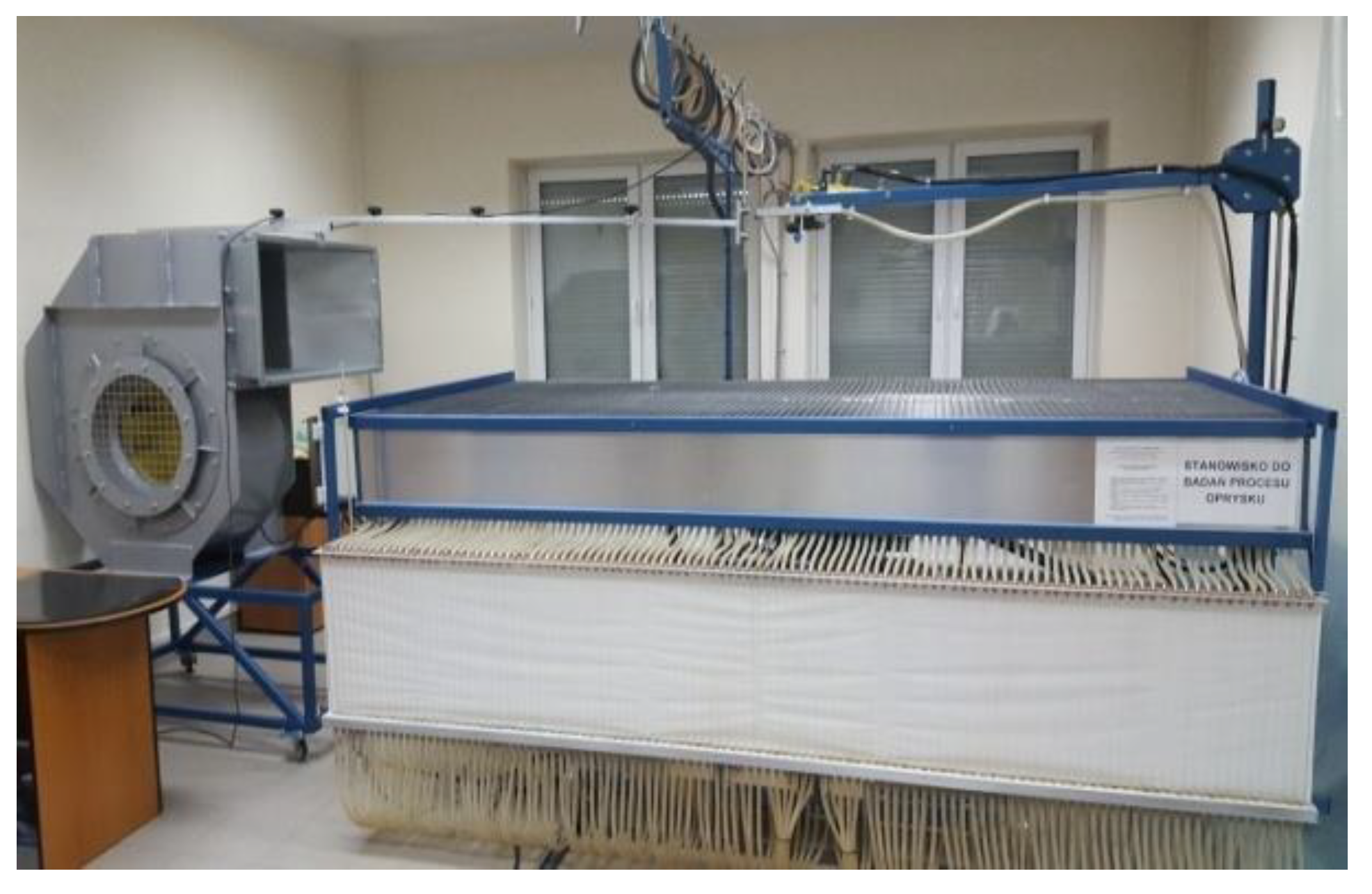
  • During measurements, a constant value of the spraying boom height above the measuring table surface of 0.4 m and working pressure of 3 bar were maintained;
  • The duration of each measurement was 120 s;
  • The accuracy of liquid volume reading in a single measuring vessel was ±1 mL;
  • The ambient temperature during tests was 20 ± 2 °C, with relative humidity of 40%–80%;
  • The accuracy of the working pressure reading was ±0.1 bar;
  • The accuracy of the nozzle’s height reading above the measuring table was ±0.005 m;
  • The accuracy of the nozzle’s angle reading in relation to the horizontal was ±1° [15].
The automatic monitoring and control system developed by the authors, which was equipped with a laboratory stand, allowed fluctuations in working pressure to be eliminated and the assumed spray dose to be obtained at a constant level during measurements. This system consisted of a precise flow meter, pressure sensor, and valves (including stepless, pressure control, and shut-off valves) that work with a measuring card and computer. During the measurements, the station operating values and the volume of liquid accumulated in individual grooving table measuring cylinders were recorded in the computer memory. The patented computer program equipped with the stand enabled the determination of the CV coefficient value for subsequent samples of tested nozzles, as well as a spraying boom composed of the appropriate number of tested samples. The volumes of liquids coming from adjacent nozzles were aggregated in such a way that the liquid streams overlapped and the axis of the nozzles were spaced every 0.5 m, which gave the same liquid distribution as for the actual field spraying boom [23]. Based on the results obtained in this way, the values of the CV coefficient for the spraying boom were calculated.
In the main part of the research, measurements of the droplet spectrum in the liquid stream were performed using the 2D-LDA/PDA laser analyzer by Dantec Dynamics.
The relevant elements of the Doppler analyzer are shown in Figure 2.
The analyzer probes were placed on a three-axis traverse system, enabling automated multipoint measurement in the measurement space. The 3D traverse system had a positioning resolution of 10 µm and was controlled by 2D-LDA/PDA analyzer software. During the tests, subsequent droplets passed through a small sample volume in the area of two intersecting laser beams, scattering the light by refraction [24,25,26]. The receiving optics were set at an angle of 43.5° in relation to the laser beam, which ensured the dominance of the refraction of the light scattering mode. For the receiving probe, a B-type aperture mask (average size up to 644.2 µm) and a 0.2 mm gap were used in the test. Table 1 presents the main parameters of the 2D-LDA/PDA analyzer.
The spectrum of the droplets produced by the nozzle was examined at a pressure of 3 bar. Measurements were made by spraying water at a temperature of 20 ± 2 °C. Environmental conditions were kept constant by conducting tests at a temperature of 20 ± 2 °C and relative humidity of 40%–80%. Measurements were made at a measuring distance of hz = 0.4 m from the nozzle (Figure 3) (ISO/FDIS 25358-2018) [27]. The assumed measuring height is consistent with the height of the nozzle position above the surface of the multigrooved table, which was adopted during tests and for evaluation of the transverse distribution of liquid volume. A multipoint measurement was made in the x-axis of the nozzle, with a measuring step of Δx = 25 mm. Chapple and Hall (1993) showed the usefulness of this method for measuring the properties of agricultural spraying and found that a single measurement along the long axis gave an appropriate representation of the entire spraying process [28].
Figure 3 shows the 44 discrete measuring points during measurement with a PDA analyzer in the spray stream, in which the droplet size and number were measured. The positioning of the PDA analyzer measuring space was carried out on the basis of a defined traverse measuring grid. The subsequent positions of the measuring space correspond to the midpoints of the measuring grooves of the table used in the method for assessment of the transverse liquid volume distribution. The measurement at each point was made for a measurement time of t = 180 s.
During the measurements, the average diameters were recorded for each measuring point, namely arithmetic, surface, volumetric, Sauter (D10, D20, D30, D32), and volumetric diameters, below which smaller drops represent 10%, 50%, 90%, and 98% of the total volume at this point (Dv0.1, Dv0.5, Dv0.9 and Dv0.98, respectively). Relative span factor (RSF) values and percentage of total droplet volume less than 100 μm were also recorded at subsequent measuring points (V100).
The relative span factor (RSF) is a dimensionless parameter indicating the homogeneity of the droplet size distribution, defined as:
RSF = Dv 0.9 Dv 0.1 Dv 0.5

3. Results and Discussion

Table 2 presents the test results for 7 randomly selected RS11003 nozzles and the TP11003-SS reference nozzle, determined on the basis of measurements of the transverse distribution of liquid volume on a standardized grooved table, along with the results of measured unit flow rates. A graphic interpretation of the transverse distribution of the liquid collected in grooves equal to 25 mm in width for the tested specimens is presented in the chart below (Figure 4). For each sample tested, the values of the CV coefficient determined for a single nozzle, the spraying boom, and nozzle assembly are presented. The results are ordered by measurement order. The determined values of the CV coefficient for individual nozzles fulfill a comparative role, while those determined for the spraying boom become a direct assessment of the spraying quality.
The analysis of the results (Table 2) indicates that when submitting identical nozzle samples for the spraying boom, the obtained were CV values below the maximum permissible value of 10%. The unit flow rate for the tested samples was within ±5% of the nominal flow rate. It can be concluded that in light of the presented work quality assessments, the tested nozzles meet the criteria, which are additionally supplemented by the manufacturer’s information on the optimal fraction of produced droplets. It was noted that despite positive assessments, there are large differences in the distribution of the plant protection product. Observations of a similar nature were observed in studies conducted by other authors [29]. The analysis of the transverse volume distribution, measured on a grooved table (Figure 4), shows a clear change in the nature of the volume distribution for individual spray assessments. It is natural for this type of nozzle to achieve a decreasing liquid volume distribution as it moves away from the nozzle axis (Figure 4, TeeJet TP11003-SS reference nozzle). A significant and unforeseen increase in volume for the RS11003 nozzles subjected to the test was observed at measuring positions 20 to 22 (462.5–512.5 mm; Figure 4) for the right side of the stream. For nozzle number 2, an increase in volume was also noted in the left part of the stream at measuring positions 18 to 20. For basic research in the field of spray spectrum evaluation in selected bands (measuring ranges) and for analysis of spray stream areas in which the volume increase was noted, nozzle number 2 was selected, the volume distribution histogram for which is presented in Figure 5. The list of measurement results is presented in Table 3.
Based on the analysis of the test results, Dv0.5 (VMD) variability was found in the range of 241–262 µm as it moved away from the nozzle axis. Such a small change in volume median diameter (VMD) was observed up to scanning position x = 337.5 mm for the left and right parts of the tested stream (Table 3, Figure 6 and Figure 7).
Past research [30] has shown that VMD grows in the stream as it moves away from the axis, which is natural for flat fan agricultural nozzles. It was also found that despite a decrease in the number of measured droplets in subsequent samples as they move away from the spray stream axis, the measurement accuracy was reduced, however the obtained volume median diameter (VMD) value was reliable. Above x = 337.5 mm, an increase of Dv0.5 by 20–40 µm on average was noted at subsequent measuring points, which is natural for these types of nozzles. The number of discrete measurement points was adjusted to obtain a maximum deviation of Dv0.5 between subsequent measurements of ± 10% (ISO/FDIS 25358-2018). An increase in the value of the diameter of the droplet spectrum and a decreasing number of occurrences in this area of the stream results in the correct distribution of liquid volume, which was also noted in studies that assessed the transverse distribution of liquid volume. A significant increase in the value of VMD was found in measuring positions 20 to 22 (462.5–512.5 mm; Figure 7). On the right side, streams averaged 170 µm, while a slightly lower value of 95 µm on average was noted in the same positions for the left. A significant decrease in the value of the relative span factor (RSF) was also noted in these measuring positions, which clearly indicates a decrease in the uniformity of the droplet size distribution. A decrease in the value (V100) from a level of about 5% in the area of the nozzle axis to values of 0.1%–0.2% at these measuring points indicates the occurrence of droplet spectra with diameters greater than 100 µm.
Although a drop in the number of droplet occurrences was noted in these areas (Figure 8), such a significant increase in diameter in the spraying spectra characterized by diameters Dv0.1, Dv0.5, and Dv0.9 resulted in disruption of the liquid volume distribution in these spray bands (Figure 9). This state was confirmed by the results obtained in the assessment of the volume distribution, which was determined for the nozzle on a multigrooved table, as well as by the results of the volume distribution determined on the basis of average volume diameter D30 and the number of drops at subsequent measuring points (Figure 10).
According to the ASABE S572.1 reference, the diameter of the volume median diameter (Dv0.5 = 280.5 µm) was obtained for the spray stream, which standardizes the nozzle to the medium droplet class (236–340 µm). A decrease in the volume median diameter value was observed to the level of Dv0.5 = 266.5 µm for the stream in which measuring areas were omitted, in which the disturbance of the liquid volume distribution was noted. In the areas of disturbance on the right side, an average Dv0.5 V 417.6 µm was noted, resulting in very coarse droplets (404–502 µm), while for the left side an average volume median diameter Dv0.5 value of 347.9 µm was noted, which corresponds to the coarse droplet class (341–403 µm). It can be concluded that according to the spray spectrum, the droplet class within the fine–medium range dedicated to this group of nozzles (RS11003) was obtained for the entire stream. However, in areas where special attention was paid, an increase in liquid volume was demonstrated as a result of testing the transverse distribution, which results from a clear increase in droplet diameter in the spectrum, despite the reduced occurrence. Studies have shown a significant change in droplet size, ranging from the medium level used to assess the entire stream, to coarse and very coarse droplets in disturbance areas. This affects the spray structure. Significant differences in the droplet size in individual spraying bands can affect the biological effectiveness of the plant protection product used. In such cases, the threat to the natural environment is very significant as a result of concentration (overlapping) of spraying bands of increased volume, especially in the assembly of nozzles on the spraying boom. The variability of the median volume in this range affects the liquid retention on plants, dripping, and penetration of droplets in the crop.

4. Conclusions

The presented research results and their analysis led to the following conclusions:
  • The tested nozzles sufficiently meet the generalized criteria regarding macroparameters (unit flow rate, CV coefficient) and microparameters, including qualification in the field of optimal fraction for produced droplets at the medium level (236–340 µm). This is also confirmed by the results of numerous studies carried out in other scientific centers and research institutions.
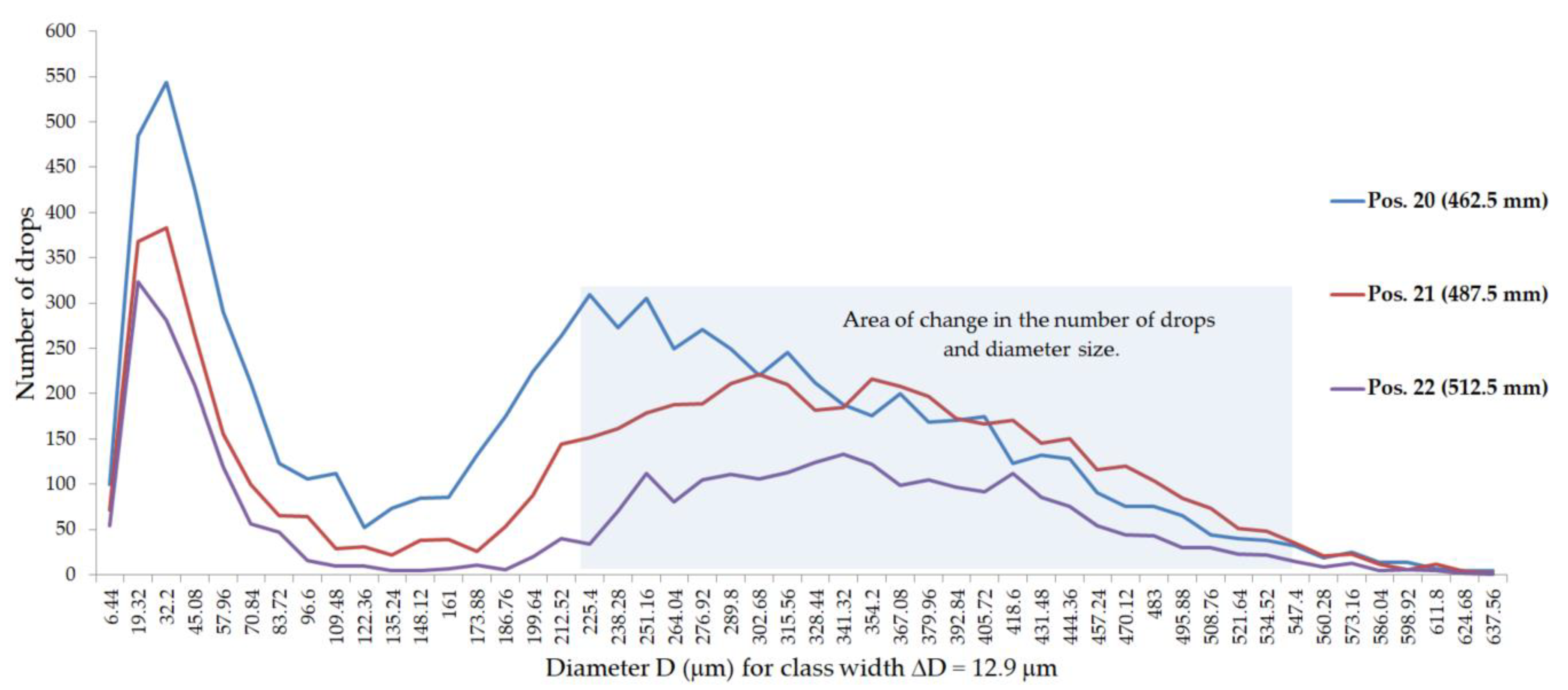
  • Pronounced changes in the nature of the volume distribution (volume increase) observed in specific bands of the sprayed stream during the nozzle tests caused a significant change in droplet size, ranging from the medium level for the assessment of the entire stream to coarse or even very coarse droplets. The assembly of such streams emitted by nozzles located on the spraying boom can lead to the synergistic effect of the described disturbances in the considered areas and can contribute to a significant deterioration in the quality and effectiveness of spraying. The effects of poor spraying quality include reduced treatment effectiveness (reduced pest or disease control) or crop damage (overdose of a plant protection product). These effects can also lead to environmental hazards and economic losses.
  • In cases where the volume distribution shows a clear and local change in character despite a positive verification result, the authors recommend carrying out additional tests, consisting of spot measurement of droplet characteristics in individual bands of the liquid stream corresponding to the width of a single groove of a grooved table.
  • The Doppler laser anemometry method can be used to assess the lateral distribution of liquids on sprayed surfaces and to determine the corresponding value of the CV coefficient as an alternative to analogous measurements on a grooved table. This is confirmed by the results presented in Figure 10.

Author Contributions

Conceptualization, D.L. and J.P.; methodology, D.L. and J.P.; data curation, D.L. and J.P.; writing—review and editing, D.L. and J.P.; visualization, W.M. All authors have read and agreed to the published version of the manuscript.

Funding

This research received no external funding.

Conflicts of Interest

The authors declare no conflict of interest.

References

  1. Sikkema, P.H.; Brown, L.; Shropshire, C.; Spieser, H.; Soltani, N. Flat fan and air induction nozzles affect soybean herbicide efficacy. Weed Biol. Manag. 2008, 8, 31–38. [Google Scholar] [CrossRef]
  2. Balsari, P.; Grella, M.; Marucco, P.; Matta, F.; Miranda-Fuentes, A. Assessing the influence of air speed and liquid flow rate on the droplet size and homogeneity in pneumatic spraying. Pest Manag. Sci. 2019, 75, 366–379. [Google Scholar] [CrossRef] [PubMed]
  3. Butler Ellis, M.C.; Lane, A.G.; O’Sullivan, C.M.; Miller, P.C.H.; Glass, C.R. Bystander exposure to pesticide spray drift: New data for model development and validation. Biosyst. Eng 2009, 107, 162–168. [Google Scholar] [CrossRef]
  4. Carlsen, S.C.K.; Spliid, N.H.; Svensmark, B. Drift of 10 herbicides after tractor spray application. 2. Primary drift (droplet drift). Chemosphere 2006, 64, 778–786. [Google Scholar] [CrossRef]
  5. Dorr, G.J.; Hewitt, A.J.; Adkins, S.W.; Hanan, J.; Zhang, H.; Noller, B. A Comparison of Initial Spray Characteristics Produced by Agricultural Nozzles. Crop Prot. 2013, 53, 109–117. [Google Scholar] [CrossRef]
  6. Grisso, R.B.; Hipkins, P.; Askew, S.D.; Hipkins, L.; Mccall, D. Nozzles: Selection and Sizing. In Virginia Cooperative Extension; Virginia Tech: Blacksburg, VA, USA, 2019; pp. 1–12. [Google Scholar]
  7. Czaczyk, Z. Working characteristics of selected flat fan nozzles for protection of field crops. J. Res. Appl. Agric. Eng. 2012, 57, 31–40. [Google Scholar]
  8. Łuczycka, D.; Szewczyk, A.; Cieniawska, B. Nierównomierność pokrycia opryskiwanych obiektów wybranymi rozpylaczami jedno- i dwustrumieniowymi. Inżynieria Rolnicza 2014, 1, 101–110. [Google Scholar]
  9. Manzone, M.; Demeneghi, M.; Marucco, P.; Grella, M.; Balsari, P. Technical solutions for under-row weed control in vineyards: Efficacy, costs and environmental aspects analysis. J. Agric. Eng. 2020, 51, 36–42. [Google Scholar] [CrossRef] [Green Version]
  10. Kang, F.; Wang, H.; Pierce, F.J.; Zhang, Q.; Wang, S. Sucker detection of grapevines for targeted spray using optical sensors. Trans. of ASABE 2014, 55, 2007–2014. [Google Scholar] [CrossRef]
  11. Doble, S.J.; Matthews, G.A.; Rutherford, I.; Southcombe, E.S.E. A system for classifying hydraulic nozzles and other atomizers into categories of spray quality. Proc. Br. Crop Protection Conf Weds, Bracknell 1985, 9, 1125–1134. [Google Scholar]
  12. ANSI/ASAE S572.1. Spray Nozzle Classification by Droplet Spectra. In ASABE Standards; American Society of Agricultural and Biological Engineers: St. Joseph, MI, USA, 2009. [Google Scholar]
  13. Hewitt, A.J. Droplet size spectra classification categories in aerial application scenarios. Crop Prot. 2008, 27, 1284–1288. [Google Scholar] [CrossRef]
  14. ISO 10625 Equipment for crop protection – Sprayer nozzles – Colour coding for identification. In International Organization for Standardization; ISO: Geneva, Switzerland, 2005.
  15. ISO 5682-1 Equipment for crop protection—Spraying equipment—Part 1: Test methods for sprayer nozzles. In International Organization for Standardization; ISO: Geneva, Switzerland, 1996.
  16. Miller, P.C.H.; Butler Ellis, M.C. Effects of formulation on spray nozzle performance for applications from ground-based boom sprayers. Crop Prot. 2000, 19, 609–615. [Google Scholar] [CrossRef]
  17. Triloff, P.; Baecker, G.; Schmidt, K.; Czaczyk, Z.; Kleisinger, S. Determination of the drift potential of orchard sprayers under optimized operating conditions. In Proceedings of the Workshop on Spray Application Technique in Fruit Growing –SuProFruit, Alnarp, Sweden, 12–14 September 2007; pp. 38–39. [Google Scholar]
  18. Nuyttens, D.; De Schampheleire, M.; Verboven, P.; Brusselman, E.; Dekeyser, D. Droplet size and velocity characteristics of agricultural sprays. In Transactions of the ASABE; American Society of Agricultural and Biological Engineers: St. Joseph, MI, USA, 2009; Volume 52, pp. 1471–1480. [Google Scholar]
  19. Czaczyk, Z. Drop-size classification according to requirements of pesticides labels. Prog. Plant Prot. 2014, 54, 111–120. [Google Scholar]
  20. Hewitt, A.J. The importance of nozzle selection and droplet size control in spray application. In Proceedings of the North American Conf. Pest. Spray Drift Manag, Portland, ME, USA, 29 March–1 April 1998; pp. 75–85. [Google Scholar]
  21. Institute of Plant Protection National Research Institute Poland. Available online: https://www.ior.poznan.pl/plik,1500,mikolajczak-x-racjonalna-technika-2012.pdf (accessed on 10 January 2020).
  22. Lodwik, D.; Pietrzyk, J. Automated Test Station for Transverse Spray Non-Uniformity. J. Res. Appl. Agric. Eng. 2013, 59, 103–106. [Google Scholar]
  23. Parafiniuk, S.; Sawa, J.; Wołos, D. Automated device for evaluation the technical condition of agricultural nozzles. Postępy Nauki i Techniki 2011, 10, 39–48. [Google Scholar]
  24. Nuyttens, D.; Sonck, B.; De Schampheleire, M.; Steurbaut, W.; Baetens, K.; Verboven, P.; Nicolaï, B.; Ramon, H. A pdpa laser-based measuring set-up for the characterization of spray nozzles. Commun. Agric. Appl. Biol. Sci. 2005, 70, 1023–1035. [Google Scholar]
  25. Wang, H.; Yunhe, D.; Xiaobin, W.; Xinxin, H. An experimental comparison of the spray performance of typical. Powder Technol. 2019, 345, 580–588. [Google Scholar] [CrossRef]
  26. Tuck, C.R.; Butler Ellis, M.C.; Miller, P.C.H. Techniques for measurement of droplet size and velocity distributions in agricultural sprays. Crop Prot. 1997, 16, 619–628. [Google Scholar] [CrossRef]
  27. ISO/FDIS 25358—2018: Crop protection equipment - Droplet-size spectra from atomizers—Measurement and classification. In International Organization for Standardization; ISO: Geneva, Switzerland, 2018.
  28. Chapple, A.C.; Hall, F.R. A description of the droplet spectra produced by a flat fan nozzle. Atom. Sprays 1993, 3, 477–488. [Google Scholar]
  29. Van de Zande, J.C.; Porskamp, H.A.J.; Holterman, H.J. Influence of reference nozzle choice on spray drift classification. Aspects Appl. Biol. 66 Int. Adv. Pestic. Appl. 2002, 66, 49–56. [Google Scholar]
  30. Butler Ellis, M.C.; Tuck, C.R.; Miller, P.C.H. The effect of some adjuvants on sprays produced by agricultural flat fan nozzles. Crop Prot. 1997, 16, 41–50. [Google Scholar] [CrossRef]
Figure 1. View of the spraying process testing stand.
Applsci 10 02395 g001
Figure 2. The analyzer 2D-Laser Doppler Anemometry/Phase Doppler Anemometry (2D-LDA/PDA) from Dantec Dynamics.
Applsci 10 02395 g002
Figure 3. Diagram of the stream with marked 2D-PDA measurement points. Note: hz, measuring distance from the nozzle; Δx, measuring step.
Applsci 10 02395 g003
Figure 4. Volume distribution for the RS11003 nozzles and the reference TP11003-SS nozzle.
Applsci 10 02395 g004
Figure 5. Histogram of volume distribution for nozzle number 2 (RS11003).
Applsci 10 02395 g005
Figure 6. Cumulative percentage volumes for the left side of nozzle number 2.
Applsci 10 02395 g006
Figure 7. Cumulative percentage volumes for the right side of nozzle number 2.
Applsci 10 02395 g007
Figure 8. The number of occurrences of drops in the diameter class for nozzle number 2, right side of the stream, measuring positions 18 to 22.
Applsci 10 02395 g009
Figure 9. Distribution of volume diameters (Dv0.1, Dv0.5, Dv0.9) at measuring points in the liquid stream for nozzle number 2. Note: Dv0.1, volumetric diameter, below which smaller drops represent 10% of the total volume; Dv0.5, volumetric diameter, below which smaller drops represent 50% of the total volume; Dv0.9, volumetric diameter, below which smaller drops represent 90% of the total volume.
Applsci 10 02395 g008
Figure 10. Liquid volume distribution determined on the basis of D30 diameters obtained in 2D-PDA analysis of the size and number of drops for nozzle number 2.
Applsci 10 02395 g010
Table 1. Main 2D-LDA/PDA analyzer parameters.
2D-LDA Transceiver Probe
Probe focal length700 mm
Wavelength of laser beams660 nm and 785 nm
Laser power per pair of beams for the first component:
Laser power per pair of beams for the second component:
90 mW
70 mW
Diameter of the laser beam at the front lens2.75 ± 0.25 mm
Detection system adapted for measurements at the wavelengths compatible with the transmitting probe (i.e., 660 and 785 nm)
Built-in camera for monitoring and adjusting LDA and PDA optics
Range of measured particle sizes depending on configuration1–1600 µm
Resolution of measured quantities±0.05 µm
Measurement of the maximum number of particles>300,000 particles/second
Range of measured velocity components at any vector return0–300 m/s
Resolution of measured speeds in the range0.002%
Table 2. Test results for RS11003 nozzles and TP11003-S reference nozzle.
RS11003 TP11003-SS
No. 1No. 2No. 3No. 4No. 5No. 6No. 7References.
CV nozzle/boom (%)56.7/5.848.7/8.856.9/6.755.6/656.6/6.858/6.356.3/6.351.7/4.6
flow rate (L/min)1.161.181.151.161.171.181.181.18
x (mm)/ groovevolume (mL)
Left side of the stream512.5223.8134.13.25.83.95.35.4
487.5216.92173.964.46.49.5
462.5207.3277.64.16.14.97.215.3
437.5196.6286.69.56.45.27.819
412.51812.82714.517.812.411.614.521
387.51719.82524.825.621.922.32425
362.51621.928.527.327.325.62628.531.8
337.51525.230.228.128.528.126.829.334.7
312.51430.233.529.331.83128.932.238.4
287.51333.937.232.233.933.93334.740.5
262.51237.642.13840.140.93839.244.2
237.5114549.64547.146.343.845.450.4
212.5105257.451.254.15250.850.853.3
187.5961.16459.561.560.358.759.959.5
162.5865.767.366.96966.966.166.564
137.5768.271.571.572.769.471.567.765.7
112.5673.572.777.276.873.576.473.573.9
87.557678.983.480.579.778.580.174.4
62.548183.488.486.784.382.285.988.4
37.5389.296.298.794.290.592.193.491.3
12.5288.896.788.8101.6102.9100.8102.995
Right side of the stream01101.297.1105.7101.6103.399.6106.299
12.5210496104100.5102100.510598
37.53106.294107.8104.1106.2101.6107.494
62.54106.298.3108.6104.9105.3103.7108.295
87.55107.493.4105.3100.4107.4102.9107.896
112.5683.487.2100100.497.595.4101.292.9
137.5785.180.593.895.49593.896.292.5
162.5885.574.487.687.286.389.693.480.1
187.5986.775.279.377.777.778.587.680.1
212.51065.37180.173.174.872.375.665.3
237.51166.165.774.873.574.473.175.665.7
262.51266.157.459.167.768.657.470.262
287.51360.753.760.359.959.157.859.555.4
312.51455.446.754.955.454.545.955.452.9
337.51547.540.547.947.148.745.947.945.9
362.51643.440.943.84346.343.444.643
387.51739.734.740.939.742.540.54338.4
412.51833.930.233.53336.434.336.835.1
437.51930.231.831.432.232.228.933.933
462.52033.940.146.347.143.84343.428
487.52140.942.156.253.345.45047.125
512.52232.221.926.827.723.125.228.522.3
537.52312.46.2576.65.49.515.3
Note: CV, coefficient of variation.
Table 3. The results of the drop spectrum tests in the subsequent points of the PDA analysis for nozzle number 2.
x (mm)CountsD10 (µm)D20 (µm)D30 (µm)D32 (µm)Dv0.1 (µm)Dv0.5 (µm)Dv0.9 (µm)Dv0.98 (µm)RSFV100 (%)
Left side of the stream512.52987211.5250.4272.7323.4254.4338.2434.85250.530.2
487.55311234266.6286.7331.5248351.1460.6537.90.610.1
462.57405236.9266.2285.1327.2241.6344.6460.6531.40.640.1
437.511504211238.6258.2302.3215.8325.3447.7531.40.710.2
412.514050183.7210.7230.2275196.5293.1415.5505.70.750.4
387.515641166.1192.8212.5258183.6280.2389.7512.10.740.7
362.519600154.6180199.8246.1170.7267.3389.7537.90.821
337.524595140.4165.1185232.3157.8254.4383.3537.90.891.5
312.529813133.9158178.1226.4151.4254.4383.3531.40.911.8
287.537059127.1152.4174.4228.3151.4254.4421.9557.21.062.1
262.548475121146.6169.4226144.9260.9415.5531.41.042.6
237.558752114.4140.6164.1223.5144.9254.4415.5537.91.062.9
212.571748107.6132.8156.2215.9132.1248415.5550.81.143.6
187.582103102.7128.1151.8212.9132.1254.4409544.31.094.1
162.59510098.1123.4147.5210.6125.6254.4415.5537.91.144.6
137.510500894.4119.2143.3206.9125.6248415.55251.175.2
112.511198392.8117.8142.1206.7125.6248409537.91.145.4
87.512042093.6119.3144.6212.2125.6260.9421.9550.81.145.1
62.512948393.9120.5146.6216.8125.6267.3441.3563.71.184.9
37.513436493.4119.7145.4214.6125.6260.9428.4550.81.165
12.513515093119.1144.5212.8125.6260.9421.9550.81.145.1
Right side of the stream013633693119.2144.5212.5125.6260.9409531.41.095.1
12.513506290.7116.3141207.5125.6254.44095251.115.5
37.513470691.9118.2144213.7125.6260.9428.4557.21.165.2
62.513107091.2117142.3210.4125.6260.9428.4557.21.165.3
87.512860691.5117.4143.1212.5125.6260.9434.8570.11.195.3
112.512180691.3116.5141.2207.3125.6254.4415.5537.91.145.4
137.511397491.7116.9141.5207.3125.6254.4415.5544.31.145.3
162.510617192.2116.9140.6203.6125.6241.6409.0563.71.175.4
187.59285895.5120.7144.8208.3125.6248415.5563.71.174.9
212.58040399.1124.0147.3207.8132.1241.6409544.31.154.5
237.568252103.0127.5150.2208.4132.1241.6409544.31.154.2
262.553408109.5133.7155.5210.3132.1241.6396.2518.61.093.6
287.544333114.9139.8162217.6138.5248409544.31.093
312.535874121.8146.3167.6219.9144.9248402.6531.41.042.6
337.528990128.1153.1174.1225.1151.4248396.2518.60.992.1
362.525049136.6162.7184.1235.5157.8260.9409.0531.40.961.6
387.518675149.4177.8199.9252.5177.1273.8402.65250.821.0
412.514119163.7194.2217.1271.4190.0293.1441.3544.30.860.7
437.59629186.1222.4248.1308.9215.8338.2467563.70.740.4
462.57836229.2273.4303.2372.7267.3409544.3602.30.680.2
487.55957268.9311.8338.1397.6299.5428.4537.9602.30.560.1
512.53299247.3298.1327.5395.3299.5415.5537.9602.30.570.1
537.51927175.7236272.4362.9286.7376.8486.4589.40.530.3
Note: D10, arithmetic average diameter; D20, surface average diameter; D30, volumetric average diameter; D32, Sauter diameter; Dv0.1, volumetric diameter, below which smaller drops represent 10% of the total volume; Dv0.5, volumetric diameter, below which smaller drops represent 50% of the total volume; Dv0.9, volumetric diameter, below which smaller drops represent 90% of the total volume; Dv0.98, volumetric diameter, below which smaller drops represent 98% of the total volume; RSF, relative span factor; V100, percentage of total droplet volume less than 100 μm.

