Article

Harmonics Consequences on Drive Systems with Induction Motor

by
Horia Gheorghe Beleiu
1,*,
Virgil Maier
1,
Sorin Gheorghe Pavel
1,
Iulian Birou
2,
Constantin Sorin Pică
1 and
Pompei Cosmin Dărab
1
1
Department of Electrical Power Systems and Management, Faculty of Electrical Engineering, Technical University of Cluj-Napoca, 28 Memorandumului Street, 400114 Cluj-Napoca, Romania
2
Department of Electric Machines and Drives, Faculty of Electrical Engineering, Technical University of Cluj-Napoca, 28 Memorandumului Street, 400114 Cluj-Napoca, Romania
*
Author to whom correspondence should be addressed.
Appl. Sci. 2020, 10(4), 1528; https://doi.org/10.3390/app10041528
Submission received: 15 January 2020 / Revised: 18 February 2020 / Accepted: 20 February 2020 / Published: 24 February 2020
(This article belongs to the Section Energy Science and Technology)

Abstract

:
In the case of adjustable drives systems with an induction motor (IM), a harmonic regime is manifested, whose knowledge and analysis are always necessary. However, most studies are focused on specific drive systems, the results of these works being valid only for drive systems of the same type. The objective of the present paper was to determine the harmonics consequences not only on the technical characteristics of the IM but also on the power supply as well as on the mechanical drive system. Thus, by initiating a methodology for estimating the consequences of each voltage harmonic separately, the aim was to substantiate a generally applicable method, which allows the evaluation, for any application, of the overall effects of the harmonics. The main feature of the method used in this paper was the consideration of the presence of voltage harmonics in the stator voltage of the IM, of certain frequencies and with certain levels, and the determination of all the electrical and mechanical consequences on the model of the drive system. It has been found that the harmonics of the IM affects the power quality (PQ) of the power supply, having significant influences also on the mechanical part of the drive system.

1. Introduction

The aspects regarding the effects of the power quality (PQ) disturbances on the electromechanical receivers are justified, due to the first rank of the electricity consumed by these types of receivers, in general consumption.
Electric motors and the systems they drive are the single largest electrical end-use, consuming more than twice as much as lighting, the next largest end-use. It is estimated that electric motor-driven systems (EMDS) account for between 43% and 46% of all global electricity consumption, giving rise to about 6040 Mt of CO2 emissions. By 2030, without comprehensive and effective energy-efficiency policy measures, energy consumption from electric motors is expected to rise to 13,360 TWh per year and CO2 emissions to 8570 Mt per year. End-users now spend USD 565 billion per year on electricity used in EDMS; by 2030, that could rise to almost USD 900 billion [1].
Induction motors (IMs) account for some 68% of the energy consumption of industry worldwide; thus, to reduce the global consumption of electricity, it is essential to improve their efficiency. Furthermore, improving the efficiency of IM and drive mechanical systems might reduce around 20%–30% of the energy consumption, also reducing some 10% of the overall electricity demand [2].
IM has one disadvantage, the fact that the mechanical speed of the machine is directly coupled to the frequency of the supply voltage, which limits its flexibility when supplied directly from the grid. Although the usage of AC power converters can adjust the supply frequency, only 25% of the newly installed machines are supplied from an AC power converter [3,4]. For IM supplied directly from the AC network, it is essential to determine the tolerability limits of the different types of disturbances affecting the PQ, as well as to identify those disturbances leading to power losses, both in the machine itself and in the power grid.
The harmonics consequences are very topical, due to the increasing use of different types of static converters as well as receivers supplied by electronic power equipment [5,6,7]. The operating of motors on a polluted harmonic system results in reduced machine efficiency and service life due to the increase in iron and copper losses at the harmonic frequencies. In addition, voltage and current harmonics can affect the torque developed. More, harmonics in rotating machinery can cause vibrations and noises. Negative sequence harmonics cause negative torque which opposes the fundamental motor torque, thus causing a decrease of the global motor efficiency.
In the literature, there are numerous studies to reduce losses in the IM and, consequently, increase the efficiency of this type of motor. If the efficiency of IM is to be increased, this can be achieved at every design parameter of the machine, and the PQ of the power supply should be considered.
In [8,9,10], the authors propose estimation methods for some characteristic parameters of the IM, such as currents, losses, or efficiency, but the harmonics, unbalanced regime, or other PQ disturbances in the supply voltages are not considered.
Although the detrimental effects of a low PQ on electric motors are known, they are mostly neglected or ignored. However, some works cover both the analysis of the additional losses that are caused by supply voltage distortion and other papers address temperature rise and derating of motors under distortion [11,12,13,14]. Other works that are based on experiments usually have the harmonic content injected by programmable power supply [15,16,17]. In [18], the authors evaluate the effect of voltage distortion on the operation of IM, with a focus on a practical setup that is often encountered in industry.
In [19], motor efficiency is analyzed in the presence of voltage harmonics; however, the use of a single equivalent circuit is proposed, instead of applying the principle of superposition of the equivalent circuits corresponding to each harmonic level. In the presence of harmonics, it is not appropriate to consider a unique parameter value, such as in the cases of stator reactance, magnetizing branch reactance, rotor reactance, and rotor resistance. These parameters vary considerably with frequency, and it becomes necessary to analyze them for each harmonic circuit [20,21].
In [22], the authors present a study about supply harmonic effects on the operation of an IM, including the electrical, vibration, and torque effects analysis. Paper [23] examines how the noise and vibration level of machines is affected by the level of the current distortion.
This paper follows a systematic analysis of the effects of the voltage waveform distortion on the IM, both electrically and mechanically. For this, the supply voltages are deformed, overlapping on the fundamental of a single harmonic. The harmonics introduced at a time in the supply voltage are of negative-sequence harmonics k ∊ {5,11,17}, respectively of positive-sequence harmonics k ∊ {7,13,19}, each having the following percentage levels γVk ∊ {5%, 10%, 15%, 20%, 25%, 30%} of the fundamental. Under these conditions, the variations of root mean square (RMS) values of the stator and rotor currents, as well as the level of the stator current harmonics corresponding to the injected voltage harmonics, have been followed. In addition, the influence of the voltage harmonics on the electromagnetic torque, power factor (PF), and efficiency of the IM have been followed.
We use the MATLAB/Simulink programming environment to analyze the IM behavior in harmonics. Modeling and simulation were chosen as study methods; these have allowed the physical models of the motor to be adapted to analyze the harmonics consequences both on the IM itself and on the power grid. In addition, we could highlight possible operating situations that are difficult to put into practice.
With the proposed methodology, the estimation of the consequences of each harmonic voltage in part follows the basis for a generally applicable method to assess, for any application, the overall effects of the harmonics.

2. Methodological Aspects

2.1. Mathematical Model of the IM

The IM chosen for the study of its operation in the harmonics has the nominal data and other characteristic sizes indicated in Table 1. A nominal power was chosen from the medium power range, i.e., Pn = 4 kW, considering that these types of machines are more common in the laboratories of technical universities where they are used for experimental verifications. The machine windings are connected in a three-wire Y-configuration with isolated neutral.
The electrical part of the IM is represented by a fourth-order state-space model. All electrical variables and parameters are referred to the stator, indicated by the prime signs in the following machine equations [24]:
Vds = Rsids + dφds/dt − ωφqs;
Vqs = Rsiqs + dφqs/dt + ωφds;
V’dr = R’ri’dr + dφ’dr/dt − (ω − ωr)φ’qr;
V’qr = R’ri’qr + dφ’qr/dt + (ω − ωr)φ’dr;
Te = 1.5p(φdsiqs − φqsids),
in which
φds = Lsids + Lmi’dr;
φqs = Lsiqs + Lmi’qr;
Φ’dr = L’ri’dr + Lmids;
Φ’qr = L’ri’qr + Lmiqs;
Ls = Lls + Lm;
L’r = L’lr + Lm,
where Rs, Lls represent the stator resistance and leakage inductance; Lm—magnetizing inductance; Ls—total stator inductance; Vds, ids—d-axis stator voltage and current; Vqs, iqs—q-axis stator voltage and current; φds, φqs—stator d- and q-axis fluxes; p—number of pole pairs; ω—reference frame angular velocity; ωr—electrical angular velocity; Te—electromagnetic torque.
All stator and rotor quantities are in the arbitrary two-axis reference frame (dq frame). The subscripts used are defined as follows: d—d-axis quantity; q—q-axis quantity; r—rotor quantity; s—stator quantity; l—leakage inductance; m—magnetizing inductance.
The mechanical part of the machine is represented by a second-order system as follow:
d d t ω m = 1 J ( T e F ω m T m ) ;
d d t θ m = ω m ,
where ωm is the angular velocity of the rotor; J—combined rotor and load inertia coefficient; F—combined rotor and load viscous friction coefficient; Tm—shaft mechanical torque; θm—rotor angular position.
The physical model considered is linear, the inductivities are considered constant, so here the phenomenon of saturation of the magnetic circuit is not considered.

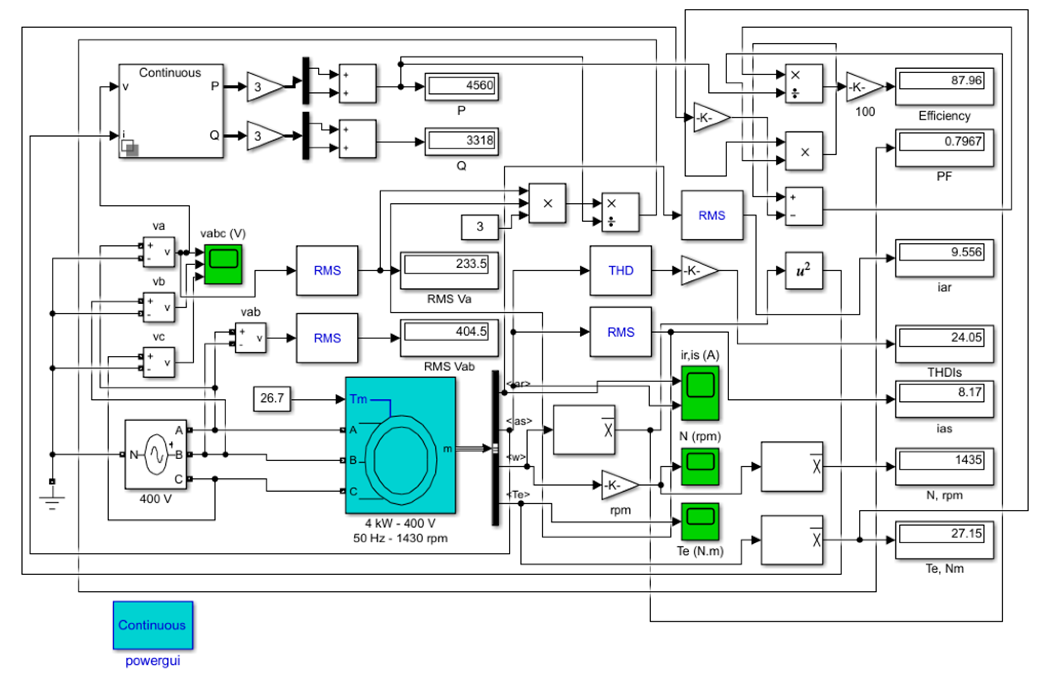
2.2. Modeling and Simulation of the IM in Harmonics

Harmonics are sinusoidal voltages or currents with frequencies that are integer multiples of the fundamental electrical system frequency. These are classified as positive-sequence harmonics: kp = 3n + 1; and negative-sequence harmonics: kn = 3n + 2, being n = 0, 1, 2. In IM, positive-sequence harmonics contribute to torque in the positive (forward) direction, and negative-sequence harmonics provide torque in the negative (backward) direction. The circulation of zero-sequence current harmonics is null because the IM is usually Delta or isolated Wye connected [15].
The model shown in Figure 1 illustrates the IM simulated in MATLAB/Simulink. The Asynchronous Machine block implements a three-phase induction machine (single squirrel-cage), operating in motor mode.
We considered the following initial hypotheses for the study of the IM behavior in the harmonics:
  • The initial reference situation is that when the IM stator is supplied with a symmetrical system of sinusoidal voltages, at the network frequency, the motor is running stable at a determined constant torque and speed.
  • The voltage waves applied to the stator are deformed, by superposing over the fundamental of a single harmonic, with orders from the series k ∊ {5, 7, 11, 13, 17, 19}, and having percentage levels among the values γVk ∊ {5%, 10%, 15%, 20%, 25%, 30%}, above the rated value of the voltage.
  • Solving the situations considered above on the physical model of the IM, the levels of the harmonics of the stator current, corresponding to those of the injected voltage, are followed. Moreover, the total harmonic distortion (THD) of the stator current, of the electromagnetic torque and its THD, the PF, and the IM efficiency are monitored as well.
The voltage THD varies in the electrical networks depending on the type, power, position, and weight of the receivers and the deforming consumers. The chosen values for the voltage THD in this paper frame the real, possible situations.
For supplying the IM in harmonics, a three-phase voltage source with programmable time variation of amplitude, phase, frequency, and harmonics is used. With this type of voltage source, two harmonics can be programmed and superimposed on the fundamental signal. Figure 2 shows the waveforms of the supply voltages in which 15% of the 5th-order harmonic was superimposed on the fundamental.
We used the RMS block for obtaining the values of the stator and rotor currents. This block computes the true RMS value of the input signal, which is calculated over a running average window of one cycle of the specified fundamental frequency:
R M S ( f ( t ) ) = 1 T t T t f ( t ) 2 d t ,
where f(t) is the input signal and T is 1/(fundamental frequency).
We chose, for graphical exemplification of the IM behavior running in harmonics, the case when in the supply voltage, 15% of the 5th-order harmonic was injected over the fundamental. Figure 3 shows some IM characteristic parameters when the supply voltage contains the abovementioned harmonic content.
The harmonic contents of both the stator current and the electromagnetic torque were obtained by using the Powergui FFT Analysis Tool, which computes THD for the analyzed signal.
We calculated the values of the rotor speed and electromagnetic torque using the Mean block, which computes the mean value of the input signal. The mean value is computed over an average running window of one cycle of the specified fundamental frequency:
M e a n ( f ( t ) ) = 1 T t T t f ( t ) d t .
For the calculation of the active (P) and reactive (Q) total powers, we used the Power Measurement block. The block outputs the power quantities for each frequency component specified as follows:
P = k = 0 n P k ,   W ;
Q = k = 1 n Q k ,   Var ,
where Pk is the active harmonic power for each harmonic k; Qk—the reactive harmonic power for each harmonic k.
Next, we calculate the PF, taking into account the harmonics, with the following relation:
P F = P i n S = P i n 3 V l I l ,
where Pin is the active input power, in W; S—the apparent power, in VA; Vl,RMS—the line-to-line voltage, in V; Il,RMS—the stator current, in A.
Finally, we determine the IM efficiency using the direct method as follows:
η = P o u t P i n 100 = P M P m P i n 100 ,   % ,
where Pout represents the active output power, in W; Pin—the active input power, in W; PM—the total mechanical power developed by the motor, in W; Pm—the mechanical losses (friction and windage losses), in W.
We compute the mechanical power with the following relation:
P M = T e ω m ,   W ,
where Te is the electromagnetic torque, in Nm; ωm—the angular velocity of the rotor, in rad/s.
The mechanical losses are determined with the following equation:
P m = F ω m 2 ,   W ,
where F represents the friction factor, in N∙m∙s; ωm—the angular velocity of the rotor, in rad/s.

3. Results

To have comparison terms at different percentage loads of the IM, currents, speed, powers, PF, and efficiency have been calculated at loads of 25%, 50%, 75%, and 100% of the rated value. We indicate the obtained data in Table 2.
The results obtained are concentrated in Table 3; we emphasize that the values in the table correspond to the motor operation in the stabilized regime under the given conditions. Based on them, a series of graphical representations were made, the interpretation of which results in the IM behavior in harmonics. The most important remark is that the presence of a specific harmonic in the voltage wave leads to the appearance of a single harmonic of current, of the same order with the harmonic of voltage, both in the stator and rotor currents. For some physical sizes, analytical identifications were searched for the highlighted dependencies, in order to provide a calculation basis for those interested.

4. Discussion

4.1. THD of the Stator Current

The first of the observed sizes is the THD for the stator current—denoted THDIS (expressed in %), represented in Figure 4—depending on the k-order and the weight γVk of the voltage harmonics.
In the considered specific case, it should be taken into account that the level γVk of a k-order harmonic is defined as the ratio between the RMS value Yk of the harmonic and the RMS value Y1 of the fundamental wave, expressed as a percentage:
γ V k = Y k Y 1 100 ,   % ,
as well as the fact that the deforming residue is defined (in AC, in the absence of a continuous component) by the following expression:
Y d e f = k = 2 k M Y k 2 ,
in which the maximum order of harmonics taken into account was noted with kM. Next, if for the THD of a nonsine wave, the expression given by the ratio expressed as a percentage between the deforming residue and the RMS value of the fundamental is adopted,
T H D = Y d e f Y 1 100 ,   % ,
we have found that, in this case, when the deformed wave contains a single harmonic, the THD of the stator current (24) is equal to the level of the respective harmonic (22), both sizes expressed as a percentage:
T H D I S = γ I S k ,   % .
Graphical representations of THDIS(k), with γVk as parameter (Figure 4), obtained by joining the corresponding points through continuous interpolation functions, lead to a second observation—a qualitative one this time: the values of THDIS depend only on the order of harmonics and the magnitude of the voltage harmonic level γVk and does not depend on its type of sequence, positive or negative.
The third observation, a quantitative one, is related to the constancy of the ratio between the THDIS and the level of the voltage harmonic γVk, for a constant specific-order k of the voltage harmonic present in the voltage wave. The calculation of this ratio leads to the results presented in Table 4.
The significant decrease of the current harmonics with the increase of their order can be explained by the significant increase of the inductive reactance of the IM when the frequency of the respective harmonics is growing. The analysis of the numerical data from Table 4 leads to the conclusion that, under the given conditions, the total harmonic distortion of the stator current, at an order k2, (THDIS)k2, can be calculated if the value of the size (THDIS)k1 is known, for a known order k1, with the approximate relation:
( T H D I S ) k 2 ( T H D I S ) k 1 k 1 k 2 .
An attempt was made to identify a relationship that would allow the calculation of the level of a stator current harmonic of the k-order, denoted γISk, when the level γVk of the voltage harmonics of the same order k, from the voltage applied to the stator, is known. Among the variants obtained, the simplest is the following relation:
γ I S k 8 γ V k k ,   % ,
based on the observation caused by the graphs from Figure 4, which cuts the lines corresponding to the ordinates with the adopted values γVk, for a (fictitious) order k ≈ 8. Checked on the data in Table 3, (26) emphasizes that the current harmonics with the order k < 8 have higher weights in the current wave than the voltage harmonic of the same order. On the other hand, for orders k > 8, the level of the current harmonics decreases (8/k)-times related to one of the corresponding voltage harmonics.
Using (27), the levels of the stator current harmonics may be calculated for each of the voltage harmonics present in the stator voltage wave, and thus, THD can be determined with the relation
T H D I S = γ I S k 2 ,
where a summation index has not been explained, because the sum is made only for those harmonic orders that have been highlighted in the stator voltage wave.

4.2. The Electromagnetic Torque of the IM

The second size taken into consideration is the electromagnetic torque of the IM, through which it interacts with the mechanical system of the driven machine. Since the fundamental harmonic of the voltage is maintained at the rated value, it is expected that the average value of the electromagnetic torque, calculated with (15), should have the value Ten = 27.15 Nm (Table 2). For this reason, in Table 3, we introduced the amplitude Tek of the torque oscillations, produced by the voltage harmonics, superimposed over the fundamental one. The amplitude of the electromagnetic torque oscillations in relation with the order and the level of the voltage harmonics is represented in Figure 5.
Data from Table 3, as well as the graphs in Figure 5, lead to the conclusion that the amplitudes of the torque oscillations decrease inversely proportional to the order of the voltage harmonics and increase directly proportional to their level, according to the proposed relation:
T e k T e n 100 9.18 γ V k k ,   % .
The oscillations of the electromagnetic torque affect only its instantaneous values, but their average effect on the electromagnetic torque of the motor is null, regardless of the kind of sequence of the voltage harmonics. For this reason, in each of the simulated situations, the average electromagnetic torque is the same, having the value corresponding to the fundamental nominal voltage, at rated load.

4.3. THD of the IM Electromagnetic Torque

In this context, it was considered useful to analyze the total harmonic distortion of the IM electromagnetic torque, noted THDTe, due to the presence of both voltage and current harmonics of the same order. The graphs plotted according to the k-order of the harmonics, having the level of the voltage harmonics γVk as a parameter, are shown in Figure 6. The fact that, in most of the situations, studied THDTe exceeds 10%—reaching up to the value of 55%—raises the question of the resulting mechanical stresses, both for the motor and the mechanical system of the driven machine. Particularly, the existence of some resonance frequencies of the parts and subassemblies from the overall mechanical system composition is of interest, as well as the fact that they are in the range (250−950) Hz.
In such cases, it is necessary to intervene in limiting the harmonics run of the stator voltage, since the mechanical measures to dampen the mechanical oscillations, as a consequence of the harmonics in the IM supply, can be heavier and more expensive.

4.4. Power Factor of the IM

From the power supply network point of view, a priority aspect is the PF of the IM, because it is known that these electric receivers have a significant weight (of about 46%) in the global electric power consumption. Based on the data in Table 3, we have drawn the graphs PF(k,γVk), in which the k-order of the harmonics is the independent variable and the level of the voltage harmonic γVk is a parameter (Figure 7).
As a first remark, PF remains constant at the rated value, PFn = 0.82, for a level of the voltage harmonics γVk = 5%, regardless of the order of the harmonics. If the level of the voltage harmonics increases to 10%, the constant character of the PF related to the order of the harmonics is preserved (Figure 7), but the constant value is lower compared to the previous case, at PF = 0.81 (decrease by 1.2% compared to the rated value). At higher values of the voltage harmonics level, γVk ≥ 15%, significant decreases of the PF appear, especially at the lower orders, k ∊ {5, 7}, so that the constant appearance returns to the higher orders, k ∊ {17, 19}.
For a weight of the voltage harmonics of γVk = 30%, the most significant decreases of the PF are recorded as follows: at the value PF = 0.72 (decrease by 12.2% compared to the rated value), when the order of the voltage harmonic is k = 5; and at PF = 0.75 (decrease by 8.5% compared to the rated value), when the order of the harmonic is k = 7 (Figure 7).

4.5. The Efficiency of the IM

In terms of energy, the efficiency is also essential along with the PF, so that its variations concerning the two variables, k and γVk, are shown in Figure 8.
As in the case of the PF, the low levels of the voltage harmonics, γVk ∊ {5%, 10%}, are felt to be imperceptible or, to a minimal extent, at the IM efficiency level. Thus, for the level, γVk = 5%, the decrease of the efficiency is Δη ≤ 0.02%, and for γUN = 10%, this is Δη ≤ 0.24% (practically imperceptible, regardless of the order of harmonics). It can also be stated that for orders k ≥ 11, even at a level of the voltage harmonics γVk = 30%, the IM efficiency does not decrease by more than 0.5%, compared to the rated value (Table 3 and Figure 8).
More significant decreases of the IM efficiency due to the harmonics are recorded in the case of the 5th-order harmonic: Δη = 1.77%, when γVk = 25%; and Δη = 2.55%, when γVk = 30%. In the case of the 7th-order harmonic, the decreases are slightly smaller: Δη = 0.87%, when γVk = 25; Δη = 1.27%, when γVk = 30%.

5. Conclusions

The identification of some dependencies, in analytical forms, between the sizes of interest and the frequency and level of the voltage harmonics, has the role of allowing us to estimate the harmonics consequences in the case of other applications, in which the harmonic composition of the stator voltage wave is known. The similarity of the voltage harmonics consequences, regardless of the type of their sequence, is one of the important observations based on the data obtained.
From an electric power point of view, the general conclusion is that the harmonics are felt both at the level of the IM, through the variations of the PF and the efficiency; as well as at the level of the power supply system, through the current harmonics introduced to it and by the decrease of the PF. In addition, the electromagnetic torque harmonics can affect the behavior, reliability, and service life of some parts of the IM mechanical system, as well as of the ones belonging to the driven technological equipment.
The proposed methodology for analyzing the effects of the harmonics on IM could be extended by the following:
  • Deformation of the voltage waves applied to the stator, by overlaying a single harmonic, with different orders and percentage levels, so that the total RMS value of the voltage is less than or equal to the rated value.
  • Introduction of two or even more harmonics into the harmonic content of the voltage wave simultaneously.
  • The study of the IM behavior in harmonics at different percentage loads such as 25%, 50%, and 75%.
  • Adaptation of the current physical model of the IM to track the effects of saturation on the current harmonics developed in the motor. The present study is a reference to assess the consequences of saturation.

Author Contributions

Conceptualization, H.G.B., V.M., and I.B.; methodology, H.G.B., V.M., and S.G.P.; software, H.G.B., C.S.P., and P.C.D.; validation, H.G.B., C.S.P., and P.C.D.; formal analysis, H.G.B., S.G.P., and I.B.; writing—original draft preparation, H.G.B. and V.M; writing—review and editing, H.G.B. and S.G.P.; visualization, H.G.B. and S.G.P.; supervision, V.M. and I.B. All authors have read and agreed to the published version of the manuscript.

Funding

This research received no external funding.

Acknowledgments

The results presented in this paper were obtained in the framework of the GNaC 2018 ARUT grant “Consequences of Power Quality Issues for Electromechanical Receivers”, research Contract no. 3092/05.02.2019, with the financial support of the Technical University of Cluj-Napoca.

Conflicts of Interest

The authors declare no conflict of interest.

References

  1. Waide, P. , Brunner, C.U. Energy-Efficiency Policy Opportunities for Electric Motor-Driven Systems; Internationnal Energy Agency: Paris, France, 2011. [Google Scholar]
  2. Santos, V.S.; Eras, J.J.C.; Gutierrez, A.S.; Ulloa, M.J.C. Assessment of the energy efficiency estimation methods on induction motors considering real-time monitoring. Measurement 2019, 136, 237–247. [Google Scholar] [CrossRef]
  3. Debruyne, C.; Lieven, V.; Jan, D. Harmonic effects on induction and line start permanent magnet machines. EEMODS 2013. [Google Scholar]
  4. Singh, G. A research survey of induction motor operation with non-sinusoidal supply wave forms. Electr. Power Syst. Res. 2005, 75, 200–213. [Google Scholar] [CrossRef]
  5. Dugan, R.C.; McGranaghan, M.F.; Santoso, S.; Beaty, H.W. Electrical Power Systems Quality, 2nd ed.; McGraw Hill Companies: New York, NY, USA, 2004. [Google Scholar]
  6. Rata, M.; Rata, G. Study solution of induction motor dynamic braking. In Proceedings of the 2016 International Conference on Development and Application Systems (DAS), Suceava, Romania, 19–21 May 2016; pp. 33–37. [Google Scholar]
  7. Rata, G.; Rata, M.; Graur, I.; Milici, D.L. Induction Motor Speed Estimator Using Rotor Slot Harmonics. Adv. Electr. Comput. Eng. 2009, 9, 70–73. [Google Scholar] [CrossRef]
  8. Bednarz, S.; Dybkowski, M. Estimation of the Induction Motor Stator and Rotor Resistance Using Active and Reactive Power Based Model Reference Adaptive System Estimator. Appl. Sci. 2019, 9, 5145. [Google Scholar] [CrossRef] [Green Version]
  9. Salomon, C.P.; Santana, W.; Lambert-Torres, G.; Da Silva, L.B.; Bonaldi, E.L.; De Oliveira, L.; Da Silva, L.E.B. Comparison among Methods for Induction Motor Low-Intrusive Efficiency Evaluation Including a New AGT Approach with a Modified Stator Resistance. Energies 2018, 11, 691. [Google Scholar] [CrossRef] [Green Version]
  10. Wang, K.; Huai, R.; Yu, Z.; Zhang, X.; Li, F.; Zhang, L. Comparison Study of Induction Motor Models Considering Iron Loss for Electric Drives. Energies 2019, 12, 503. [Google Scholar] [CrossRef] [Green Version]
  11. Debruyne, C.; Desmet, J.; Derammelaere, S.; Vandevelde, L. Derating factors for direct online induction machines when supplied with voltage harmonics: A critical view. In Proceedings of the 2011 IEEE International Electric Machines & Drives Conference (IEMDC), Niagara Falls, ON, Canada, 15–18 May 2011; pp. 1048–1052. [Google Scholar]
  12. Debruyne, C.; Corne, B.; Sergeant, P.; Desmet, J.; Vandevelde, L. Evaluation of the additional loss due to supply voltage distortion in relation to induction motor efficiency rating. In Proceedings of the 2015 IEEE International Electric Machines & Drives Conference (IEMDC), Coeur d’Alene, ID, USA, 10–13 May 2015; pp. 1881–1887. [Google Scholar]
  13. Zhang, D.; An, R.; Wu, T. Effect of voltage unbalance and distortion on the loss characteristics of three-phase cage induction motor. IET Electr. Power Appl. 2018, 12, 264–270. [Google Scholar] [CrossRef]
  14. Mirzapour, O.; Karimi-Arpanahi, S.; Oraee, H. Evaluating Grid Harmonics Effect on Induction Motor Using Reduced Thermal Model. In Proceedings of the 2018 Smart Grid Conference (SGC), Sanandaj, Iran, 28–29 November 2018; pp. 1–5. [Google Scholar]
  15. Sousa, V.; Viego, P.R.; Gomez, J.R.; Quispe, E.C.; Balbis, M. Estimating induction motor efficiency under no-controlled conditions in the presences of unbalanced and harmonics voltages. In Proceedings of the 2015 CHILEAN Conference on Electrical, Electronics Engineering, Information and Communication Technologies (CHILECON), Santiago, Chile, 28–30 October 2015; pp. 567–572. [Google Scholar]
  16. Monteagudo, F.E.L.; Carralero, L.R.; Telles, A.B.; Rivas, C.R.; Elías, M.E.G.; Varela, R.V.; García, G.E.; Ibarra, D.A.; Hernández, R.F.I. Incidence of harmonic in asynchronous three-phase motors. Procedia Eng. 2012, 35, 14–21. [Google Scholar] [CrossRef] [Green Version]
  17. Kumar, D. Performance Analysis of Three-Phase Induction Motor with AC Direct and VFD. IOP Conf. Series: Mater. Sci. Eng. 2018, 331, 012025. [Google Scholar] [CrossRef]
  18. Agamloh, E.; Peele, S.; Grappe, J. An experimental evaluation of the effect of voltage distortion on the performance of induction motors. In Proceedings of the Conference Record of 2012 Annual IEEE Pulp and Paper Industry Technical Conference (PPIC), Portland, OR, USA, 17–21 June 2012; pp. 1–7. [Google Scholar]
  19. Phumiphak, P.; Chat-Uthai, C. Nonintrusive Method for Estimating Field Efficiency of Inverter-Fed Induction Motor Using Measured Values. In Proceedings of the 2008 IEEE International Conference on Sustainable Energy Technologies, Singapore, 24–27 November 2008; pp. 580–583. [Google Scholar]
  20. Santos, V.S.; Felipe, P.R.V.; Sarduy, J.R.G.; Lemozy, N.A.; Jurado, A.; Quispe, E.C. Procedure for Determining Induction Motor Efficiency Working Under Distorted Grid Voltages. IEEE Trans. Energy Convers. 2014, 30, 331–339. [Google Scholar] [CrossRef]
  21. Chirindo, M.; Khan, M.A.; Barendse, P. Considerations for Nonintrusive Efficiency Estimation of Inverter-Fed Induction Motors. IEEE Trans. Ind. Electron. 2015, 63, 741–749. [Google Scholar] [CrossRef]
  22. Djurovic, S.; Rodriguez, D.S.V.; Smith, A. Supply Induced Interharmonic Effects in Wound Rotor and Doubly-Fed Induction Generators. IEEE Trans. Energy Convers. 2015, 30, 1397–1408. [Google Scholar] [CrossRef]
  23. Yacamini, R.; Chang, S.C. Noise and vibration from induction machines fed from harmonic sources. IEEE Trans. Energy Convers. 1995, 10, 286–292. [Google Scholar] [CrossRef]
  24. MathWorks. Available online: https://www.mathworks.com/help/physmod/sps/powersys/ref/asynchronousmachine.html (accessed on 15 January 2020).
Figure 1. Simulation of the IM in MATLAB / Simulink.
Applsci 10 01528 g001
Figure 2. Supply voltages, with 15% of the 5th-order harmonic superimposed on the fundamental.
Applsci 10 01528 g002
Figure 3. IM parameters when 15% of the 5th-order harmonic is superimposed on the supply voltage fundamental. (a)—rotor current; (b)—stator current; (c)—electromagnetic torque.
Applsci 10 01528 g003
Figure 4. THDIS dependence on the k-order and the weight γVk of the voltage harmonics.
Applsci 10 01528 g004
Figure 5. The amplitude of the electromagnetic harmonic torque of the IM in relation with the order and the level of the voltage harmonics.
Applsci 10 01528 g005
Figure 6. Total harmonic distortion factor of electromagnetic torque THDTe(k,γVk).
Applsci 10 01528 g006
Figure 7. Power factor (PF) variations of the IM in the harmonics, related to the k-order of the voltage harmonics and their level γVk.
Applsci 10 01528 g007
Figure 8. Variations of efficiency versus the harmonics order and their level, η(k,γVk).
Applsci 10 01528 g008
Table 1. Parameters of the induction motor (IM).
SymbolParameterValue
PnRated power4 kW
Vn,RMSRated line-to-line voltage400 V
fFrequency50 Hz
NnRated speed1430 rpm
RsStator resistance1.405 Ω
LlsStator leak inductance0.005839 H
RrRotor resistance1.395 Ω
LlrRotor leak inductance0.005839 H
LmMutual inductance0.1722
JInertia0.0131 kgm2
FFriction factor0.002985 Nms
pPole pairs2
PFnRated power factor0.82
ηnRated efficiency88.5%
Table 2. The characteristic sizes of the IM in the symmetrical and sinusoidal regime, for different loads.
ParameterMotor Load, %
25%50%75%100%
Stator Current—IS,RMS, A4.445.296.57.94
Rotor Current—IR,RMS, A1.941.743.19.38
Rotor Speed—N, rpm1484146814521435
Electromagnetic Torque—Te, Nm7.1313.8120.4727.15
Active Power—P, kW1.22.283.394.53
Reactive Power—Q, kVAr2.832.862.963.12
Power Factor—PF0.390.620.750.82
Efficiency—η, %86.1189.7589.6888.54
Table 3. Data on the IM behavior in harmonics at rated load.
Harmonic Order kParameterVoltage Harmonics Level of Fundamental, γVk, %
5%10%15%20%25%30%
5Stator current—IS,RMS, A7.968.048.178.348.568.82
THDIS, %8.0116.0424.0532.0540.0548.03
Rotor current—IR,RMS, A9.49.469.559.699.8510.07
Electromagnetic harmonic torque—Tek, Nm2.515.017.5110.0112.51515.02
Electromagnetic torque—THDTe, %9.2218.4427.6636.8746.0955.31
Active power—P, kW4.534.544.564.584.614.65
Reactive power—Q, kVAr3.143.23.313.473.663.91
Power factor—PF0.820.810.790.770.750.72
Efficiency—η, %88.4888.2887.9687.5186.9386.24
7Stator current—IS,RMS, A7.957.998.058.148.258.39
THDIS, %5.7411.4917.2422.9928.7434.5
Rotor current—IR,RMS, A9.399.429.479.549.649.75
Electromagnetic harmonic torque—Tek, Nm1.823.645.467.289.110.92
Electromagnetic torque—THDTe, %6.713.420.1126.8133.5140.22
Active power—P, kW4.534.534.544.554.574.59
Reactive power—Q, kVAr3.133.183.263.373.513.68
Power factor—PF0.820.810.80.790.770.75
Efficiency—η, %88.5188.4188.2588.0287.7387.38
11Stator current—IS,RMS, A7.947.967.988.028.078.13
THDIS, %3.667.3210.9814.6418.321.96
Rotor current—IR,RMS, A9.399.49.439.459.499.54
Electromagnetic harmonic torque—Tek, Nm1.042.2853.4254.575.716.85
Electromagnetic torque—THDTe, %4.218.4112.6216.8221.0325.23
Active power—P, kW4.534.534.534.544.544.55
Reactive power—Q, kVAr3.133.163.213.283.373.48
Power factor—PF0.820.810.810.80.790.77
Efficiency—η, %88.5388.4988.4288.3288.288.06
13Stator current—IS,RMS, A7.947.957.9788.038.07
THDIS, %3.096.199.2912.3915.4918.59
Rotor current—IR,RMS, A9.389.49.419.439.469.49
Electromagnetic harmonic torque—Tek, Nm0.9751.952.923.8954.875.84
Electromagnetic torque—THDTe, %3.597.1710.7614.3417.9321.52
Active power—P, kW4.534.534.534.534.544.54
Reactive power—Q, kVAr3.123.153.193.253.333.42
Power factor—PF0.820.810.810.80.790.78
Efficiency—η, %88.5388.588.4688.3988.388.2
17Stator current—IS,RMS, A7.947.947.967.977.998.02
THDIS, %2.364.737.19.4711.8514.22
Rotor current—IR,RMS, A9.389.399.49.419.439.45
Electromagnetic harmonic torque—Tek, Nm0.741.482.222.963.74.44
Electromagnetic torque—THDTe, %2.725.458.1710.8913.6216.34
Active power—P, kW4.534.534.534.534.534.54
Reactive power—Q, kVAr3.123.143.173.223.283.35
Power factor—PF0.820.810.810.80.790.78
Efficiency—η, %88.5488.5288.4988.4588.488.34
19Stator current—IS,RMS, A7.947.947.957.967.988
THDIS, %2.124.246.368.4810.612.72
Rotor current—IR,RMS, A9.389.399.49.419.429.44
Electromagnetic harmonic torque—Tek, Nm0.6651.331.9952.663.3253.99
Electromagnetic torque—THDTe, %2.454.907.359.8012.2414.69
Active power—P, kW4.534.534.534.534.534.53
Reactive power—Q, kVAr3.123.143.173.213.263.33
Power factor—PF0.820.810.810.80790.78
Efficiency—η, %88.5488.5288.588.4788.4388.38
Table 4. The values of the ratio THDISVk related to the harmonic voltage order.
Harmonic Order kTHDISVk
51.600
71.149
110.732
130.619
170.473
190.424

