Design of a Hand-Launched Solar-Powered Unmanned Aerial Vehicle (UAV) System for Plateau

Abstract
1. Introduction
2. Conceptual Design Method
2.1. Power of Level Flight
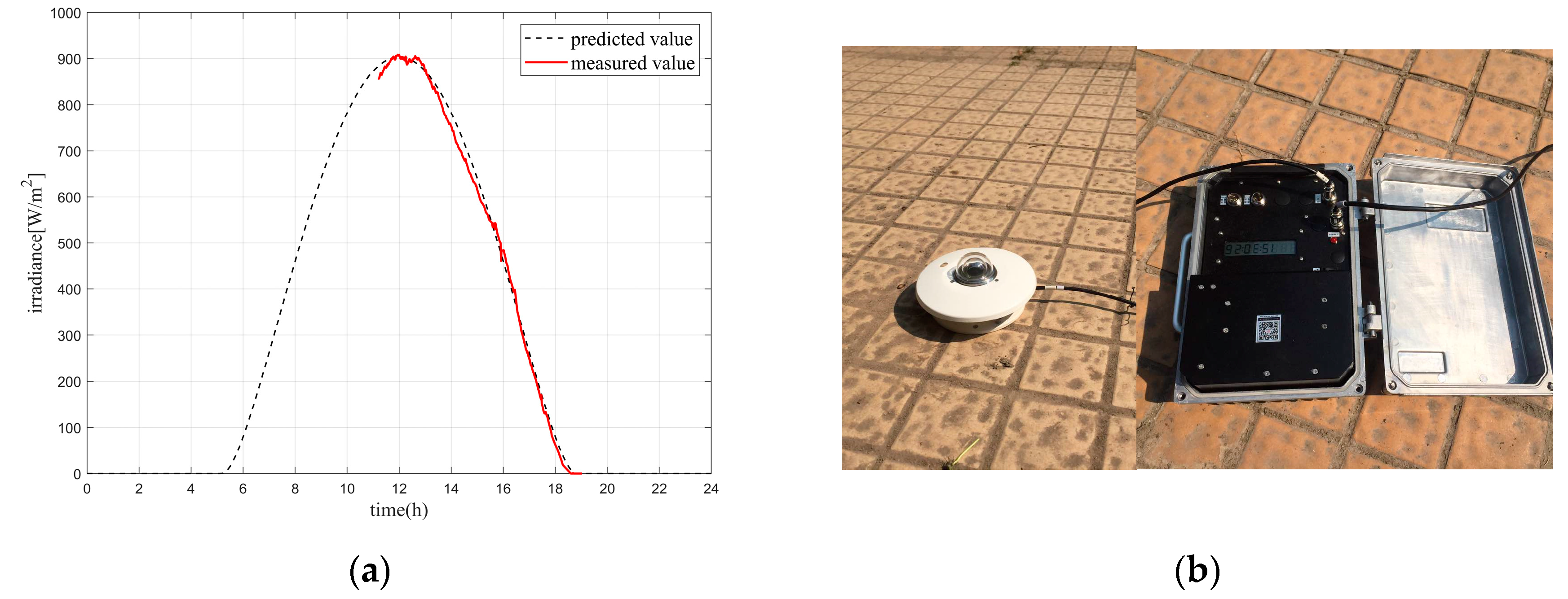
2.2. Solar Energy Obtained during the Day
2.3. Weight Estimation Model
3. Detailed Design
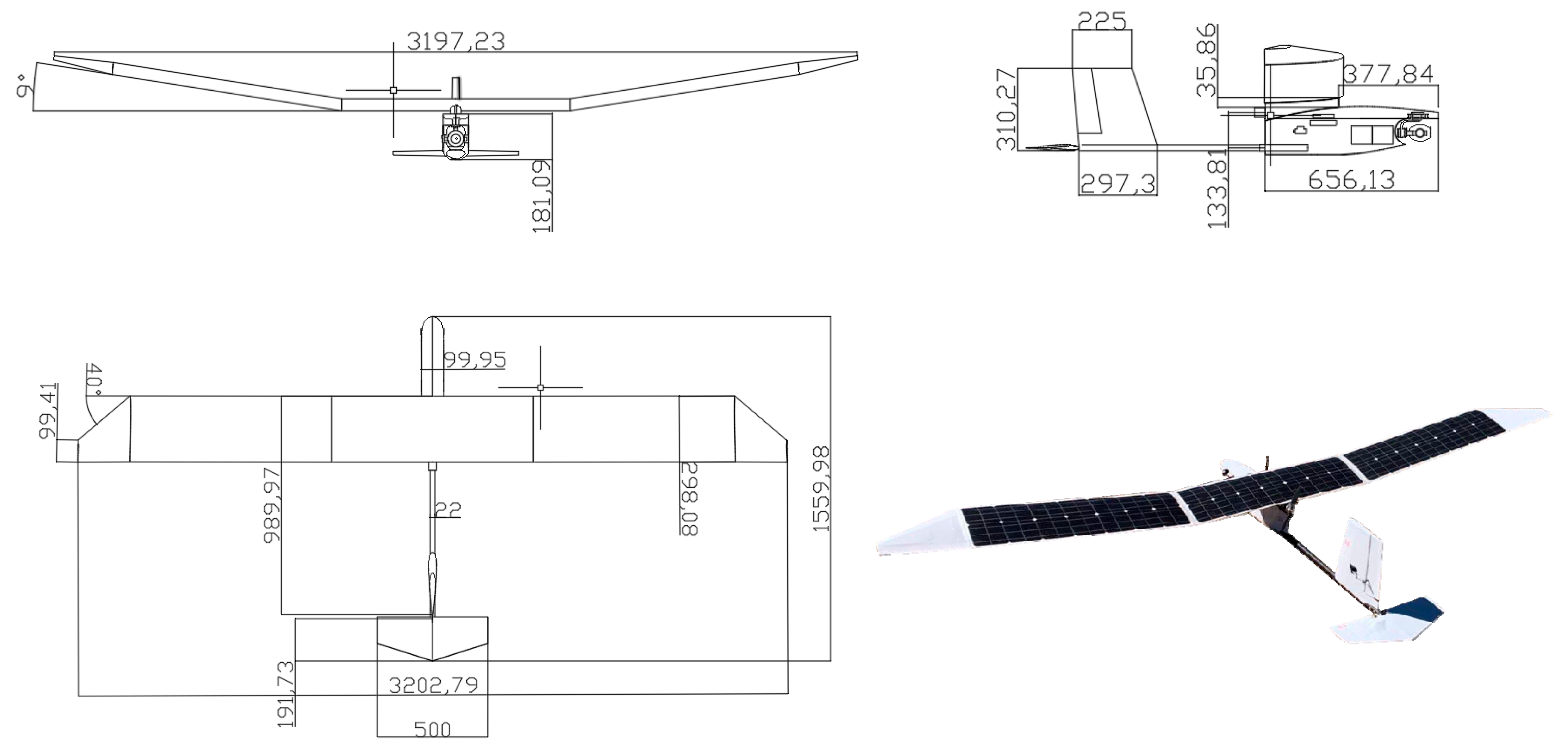
3.1. Layout Design
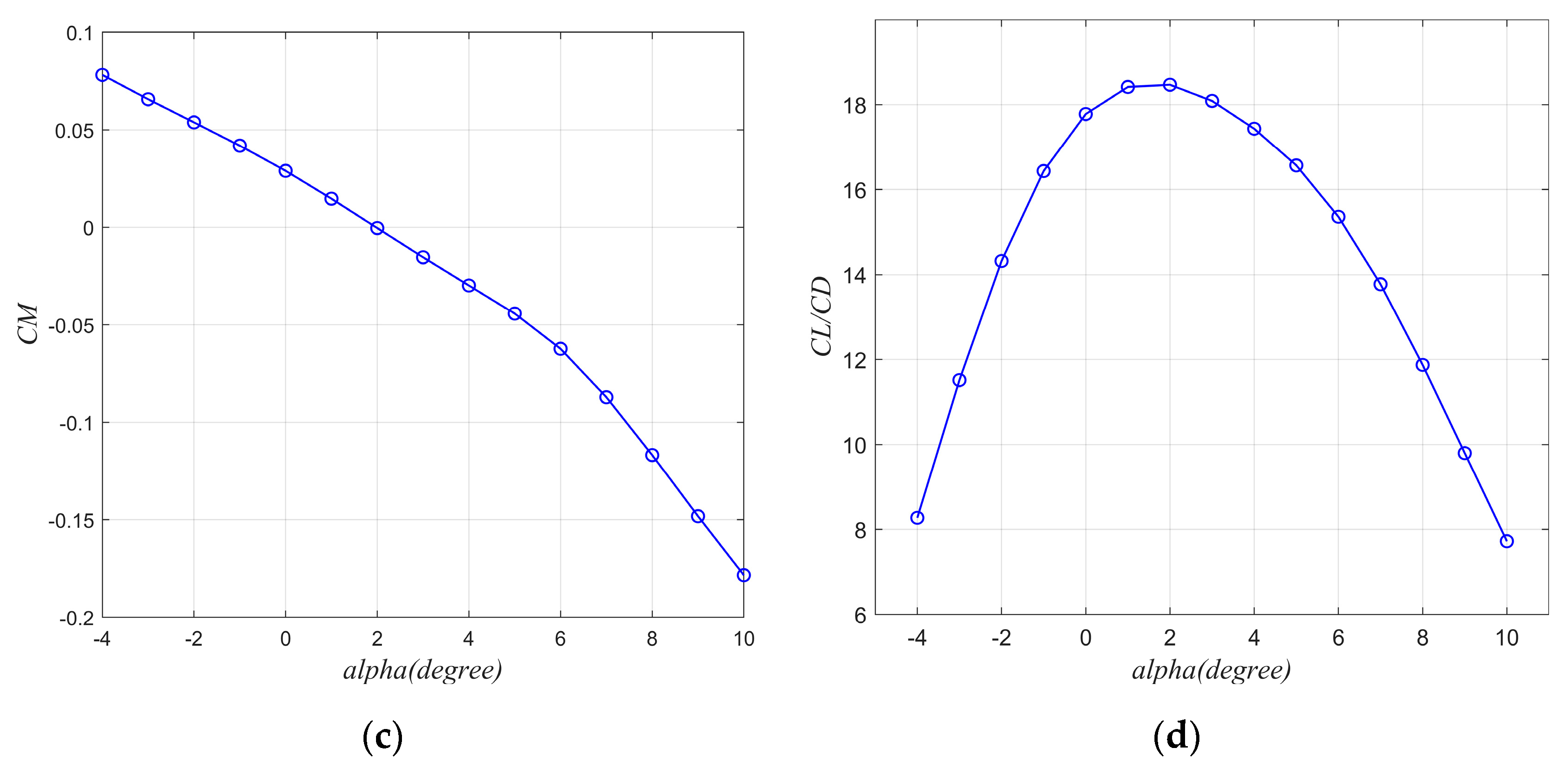
3.2. Aerodynamic Design
3.3. Structure and Avionics
4. UAV Flight Control
4.1. Lateral-Directional Nonlinear Dynamic Model
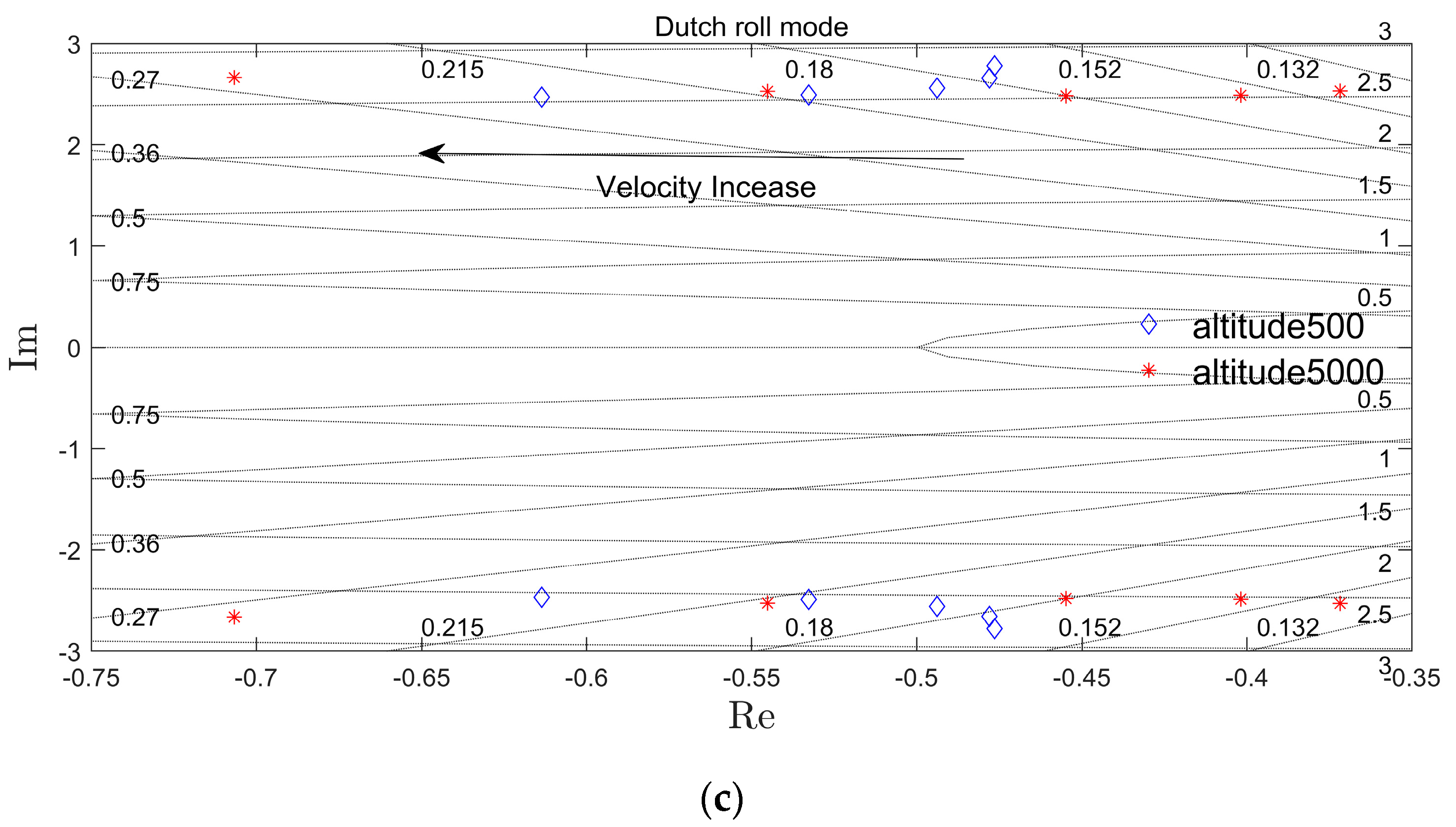
4.2. Analysis of Stability and Flight Quality
4.3. Analysis of Lateral-Directional Maneuverability
4.4. Successive Loop Closure Flight Control
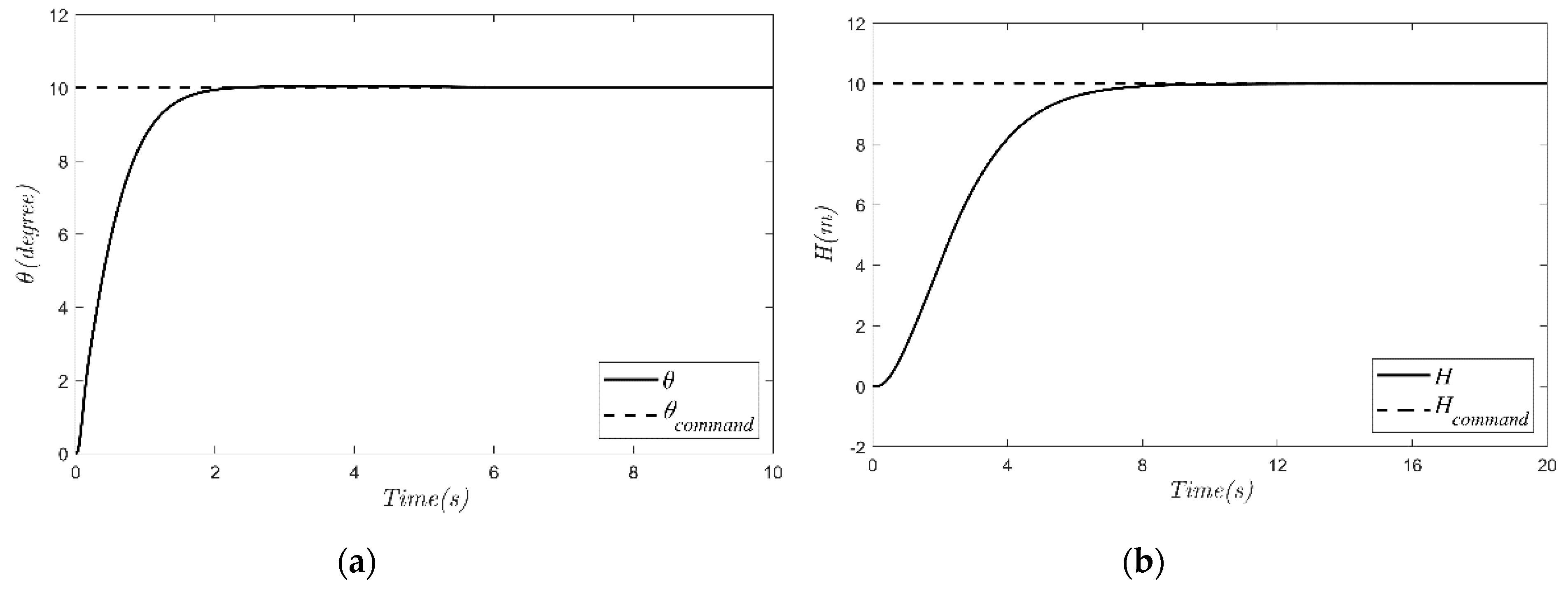
4.4.1. Longitudinal Control Law
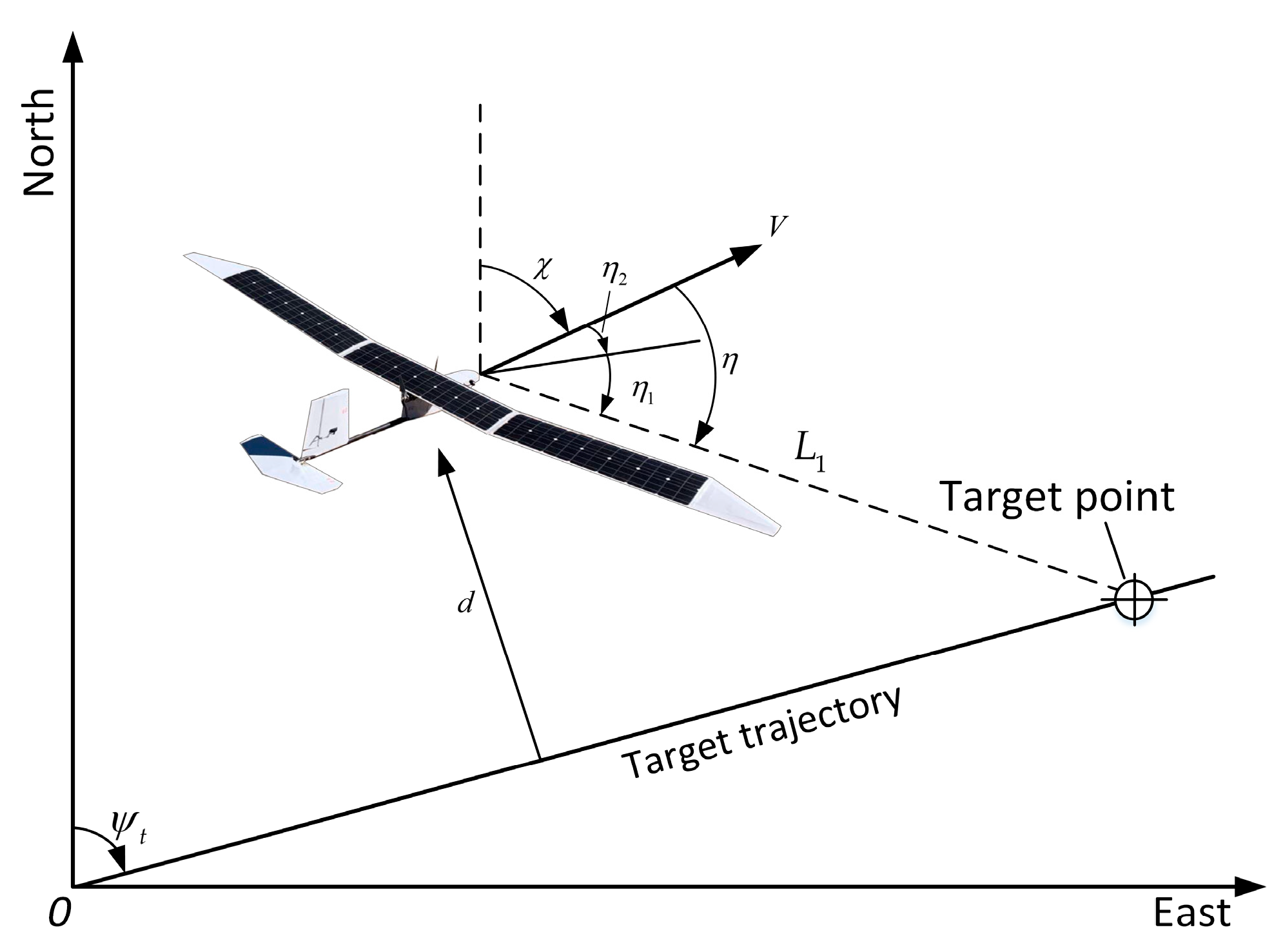
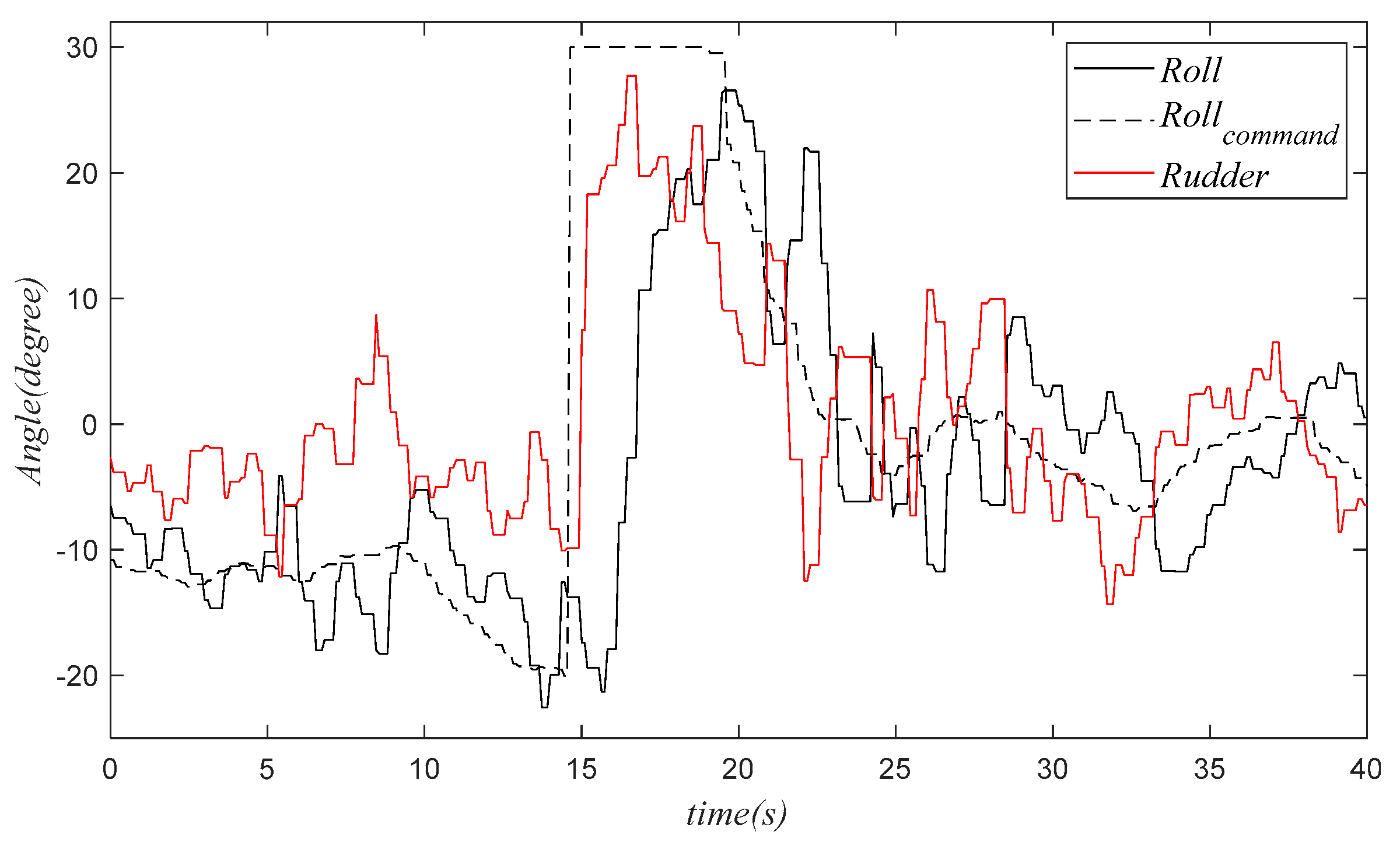
4.4.2. Lateral-Directional Control Law
5. Field Experiment
5.1. Experiment Environment
5.2. Flight Parameters of HighAltitude Experiment
6. Conclusions
Author Contributions
Funding
Conflicts of Interest
References
- Colella, N.; Wenneker, G. Pathfinder: Developing a solar rechargeable aircraft. IEEE Potentials 1996, 15, 18–23. [Google Scholar] [CrossRef]
- Helios Prototype Solar-Powered Aircraft. Available online: https://www.nasa.gov/centers/dryden/history/pastprojects/Helios/index.html (accessed on 20 December 2019).
- Solar Impulse 2 Detailed Route. Available online: https://zh.m.wikipedia.org/zh-cn/SolarImpulse2 (accessed on 6 January 2020).
- Ackerman, E. Giant Solar-Powered UAVs are Atmospheric Satellites. Available online: https://spectrum.ieee.org/automaton/robotics/drones/giant-solar-powered-uavs-are-atmospheric-satellites (accessed on 6 January 2020).
- QinetiQ, QinetiQ files for three world records for its Zephyr Solar powered UAV. Asia-Pac. Def. Rep. 2010, 36, 8.
- Airbus Zephyr S Breaks World Flight Endurance Record during Maiden Flight. Available online: https://www.sae.org/news/2018/08/airbus-zephyr-s-breaks-world-flight-endurance-record-during-maiden-flight (accessed on 6 January 2020).
- Noth, A. Design of Solar Powered Airplanes for Continuous Flight. Ph.D. Thesis, Swiss Federal Institute of Technology (ETH), Zürich, Switzerland, September 2008. [Google Scholar]
- Oettershagen, P.; Stastny, T.; Hinzmann, T. Robotic technologies for solar-powered UAVs: Fully autonomous updraft-aware aerial sensing for multiday search-and-rescue missions. J. Field Robot. 2017, 35, 1–29. [Google Scholar] [CrossRef]
- Keidel, B. Auslegung und Simulation von Hochfliegenden Dauerhaft Stationierbaren Solardrohnen. Ph.D. Thesis, Technischen Universität München, München, Germany, 2000. [Google Scholar]
- Badescu, V.; Gueymard, C.A.; Cheval, S.; Oprea, C.; Baciu, M.; Dumitrescu, A.; Iacobescu, F.; Milos, I.; Rada, C. Computing global and diffuse solar hourly irradiation on clear sky. Review and testing of 54 models. J. Renew. Sustain. Energy Rev. 2012, 16, 1636–1656. [Google Scholar] [CrossRef]
- Romeo, G.; Frulla, G.; Cestino, E.; Corsino, G. Heliplat: Design, Aerodynamic, Structural Analysis of Long-Endurance Solar-Powered Stratospheric Platform. J. J. Aircr. 2004, 41, 1505–1520. [Google Scholar] [CrossRef]
- Youngblood, J.W.; Talay, T.A.; Pegg, R.J. Design of Long-Endurance Unmanned Airplanes Incorporating Solar and Fuel Cell Propulsion. In Proceedings of the The 20th Joint Propulsion Conference, AIAA-84-1430, Cincinnati, OH, USA, 11–13 June 1984. [Google Scholar]
- Rizzo, E.; Frediani, A. A Model for Solar Powered Aircraft Preliminary Design. In Proceedings of the International Conference on Computational & Experimental Engineering & Sciences 04, Madeira, Portugal, 26–29 July 2004; Volume 1, pp. 39–54. [Google Scholar]
- Ebeid, E.; Skriver, M.; Terkildsen, K.H.; Jensen, K.; Schultz, U.P. A Survey of Open-Source UAV Flight Controllers and Flight Simulators. Microprocess. Microsyst. 2018, 61, 11–20. [Google Scholar] [CrossRef]
- Arifianto, O.; Farhood, M. Development and Modeling of a Low-Cost Unmanned Aerial Vehicle Research Platform. J. Intell. Robot. Syst. 2015, 80, 139–164. [Google Scholar] [CrossRef]
- Cheng, X.; Wang, H.P.; Zhang, Y.Z. Electric and no aileron SUAV’s lateral-direct dynamic characters. Flight Dyn. 2009, 27, 74–77. (In Chinese) [Google Scholar]
- Beard, R.W.; Mclain, T.W. Small Unmanned Aircraft: Theory and Practice; Princeton University Press: Princeton, NJ, USA, 2012; pp. 52–92. [Google Scholar]
- Bandu, N.P. Performance, Stability, Dynamics, and Control of Airplanes; American Institute of Aeronautics and Astronautics: Reston, VA, USA, 2013; pp. 511–514. (In Chinese) [Google Scholar]
- Ma, Z.Y.; Zhu, X.P.; Zhou, Z. A lateral-directional control method combining rudder and propeller for full-wing solar-powered UAV. J. Acta Aeronaut. Et Astronaut. Sin. 2018, 39, 321633. (In Chinese) [Google Scholar]
- Ma, Z.Y.; Zhu, X.P.; Zhou, Z. On-ground lateral direction control for an unswept fly-wing UAV. Aeronaut. J. 2019, 123, 416–432. [Google Scholar] [CrossRef]
- Park, S.; Deyst, J.; How, J.P. A new nonlinear guidance logic for trajectory tracking. In Proceedings of the AIAA Guidance, Navigation, and Control Conference an Exhibit, Reston, VA, USA, 16–19 August 2004. [Google Scholar]
- Guo, A.; Zhou, Z.; Zhu, X.; Bai, F. Low-Cost Sensors State Estimation Algorithm for a Small Hand-Launched Solar-Powered UAV. Sensors 2019, 19, 4627. [Google Scholar] [CrossRef] [PubMed]


| Parameter | Value | Unit | Description |
|---|---|---|---|
| 0.8 | - | Lift coefficient | |
| 0.04 | - | Drag coefficient | |
| 950 | [W/m2] | Maximum irradiance | |
| 0.89 | Temperature influence factor (5 °C) | ||
| 290 | [Wh/kg] | Energy density of Li-ion battery | |
| 0.29 | [kg/m2] | Mass density of solar cells | |
| 0.13 | [kg/m2] | Mass density of encapsulation | |
| 0.0042 | [kg/W] | Mass to power ratio of MPPT | |
| 0.008 | [kg/W] | Mass to power ratio of propulsion group | |
| 0.44/9.81 | [kg/m3] | Structural mass constant | |
| 0.11 | [kg] | Mass of autopilot system | |
| 0.8 | - | Efficiency of step-down converter | |
| 0.2 | - | Efficiency of solar cells | |
| 0.9 | - | Efficiency of the curved solar panels | |
| 0.95 | - | Efficiency of battery charge | |
| 0.95 | - | Efficiency of motor controller | |
| 0.95 | - | Efficiency of battery discharge | |
| 0.9 | - | Efficiency of motor | |
| 0.97 | - | Efficiency of MPPT | |
| 0.85 | - | Efficiency of propeller | |
| 1.5 | [W] | Power of autopilot system | |
| 3.1 | - | Airframe mass wingspan exponent | |
| −0.25 | - | Airframe mass aspect ratio exponent |
| Parameter | Value | Unit | Description |
|---|---|---|---|
| 0.1 | [kg] | Payload mass | |
| 0.85 | - | Irradiance margin factor | |
| 2 | [W] | Payload power consumption | |
| 0.78 | [kg/m3] | Air density (4500 m) | |
| 14.3 | [h] | Summer day duration (34.3° N) |
| Parameter | Value | Unit | Description |
|---|---|---|---|
| AR | 10.6 | - | Aspect ratio |
| b | 3.2 | m | Wingspan |
| Swin | 0.934 | m2 | Wing area |
| Sele | 0.06 | m2 | Horizontal tail area |
| Svert | 0.08 | m2 | Vertical tail area |
| Srud | 0.017 | m2 | Rudder area |
| VH | 0.21 | - | Horizontal tail volume |
| VV | 0.28 | - | Vertical tail volume |
| m | 2.9 | kg | Total mass |
| mbat | 1.2 | kg | Battery mass |
| mMpld | 0.6 | kg | Max payload mass |
| V | 10 | m/s | Flight speed |
© 2020 by the authors. Licensee MDPI, Basel, Switzerland. This article is an open access article distributed under the terms and conditions of the Creative Commons Attribution (CC BY) license (http://creativecommons.org/licenses/by/4.0/).
Share and Cite
Zhao, X.; Zhou, Z.; Zhu, X.; Guo, A. Design of a Hand-Launched Solar-Powered Unmanned Aerial Vehicle (UAV) System for Plateau. Appl. Sci. 2020, 10, 1300. https://doi.org/10.3390/app10041300
Zhao X, Zhou Z, Zhu X, Guo A. Design of a Hand-Launched Solar-Powered Unmanned Aerial Vehicle (UAV) System for Plateau. Applied Sciences. 2020; 10(4):1300. https://doi.org/10.3390/app10041300
Chicago/Turabian StyleZhao, Xin, Zhou Zhou, Xiaoping Zhu, and An Guo. 2020. "Design of a Hand-Launched Solar-Powered Unmanned Aerial Vehicle (UAV) System for Plateau" Applied Sciences 10, no. 4: 1300. https://doi.org/10.3390/app10041300
APA StyleZhao, X., Zhou, Z., Zhu, X., & Guo, A. (2020). Design of a Hand-Launched Solar-Powered Unmanned Aerial Vehicle (UAV) System for Plateau. Applied Sciences, 10(4), 1300. https://doi.org/10.3390/app10041300