Abstract
The main aim of this paper is to achieve the suitable SA-GEL (sodium alginate and gelatin) porous cartilage scaffold by 3D printing technology with optimal prediction parameters. Firstly, the characteristics of SA-GEL were analyzed, the influence of calcium chloride on the gel was explored, and the optimal cross-linking concentration and gelation temperature were determined. Secondly, a prediction model of the extrusion line width of SA-GEL was established, in which the printing pressure, the moving speed of the needle and the fiber interval were the important parameters affecting the printing performance of the SA-GEL composite material. Thirdly, the SA-GEL composite scaffolds were printed on the Bio-plotter platform, the C5.18 chondrocytes cells were cultured in the SA-GEL biomaterial scaffold, and the results show that the cells could survive well. These results show that, under the control of the printing parameters pressure 1.8 bar, moving speed 10.7 mm/s and the internal structure parameters of the scaffold is 0/45-1.2 (Printing interval: 1.2 mm, angle value: 45 degree), SA-GEL scaffold printing results can be obtained which have good mechanical properties and biocompatibility.
1. Introduction
Articular cartilage injury is a common and frequently occurring disease. Due to the lack of nutrition channels for mature joints, its regeneration ability is limited, and it is difficult to recover to its original state in case of injury [1]. Now there are generally the following treatment methods—drug methods, surgical methods, physical methods [2,3]. In recent years, transparent cartilage scaffold has been constructed by cartilage tissue engineering in vitro and in vivo, which provides a new method for repairing cartilage defects [4,5,6]. Cartilage tissue engineering takes chondrocytes extracted from the patient’s cartilage as seed cells, which are cultured and proliferated in vitro, and then inoculates them into biodegradable scaffolds with good mechanical properties and biocompatibility. The composite of cell scaffolds is implanted into the human body, and the chondrocytes on the scaffolds are proliferated to form tissue-engineered cartilage to repair the defect, so as to achieve the purpose of treatment. Cartilage tissue engineering consists of three parts—seed cells, growth factors and scaffolds. Scaffolds play a key role in cartilage tissue engineering, providing seed cells with channels for nutrient exchange and material metabolism with the outside world, and providing them with a stable growth environment to facilitate their adhesion, proliferation and differentiation, and necessary mechanical properties for cartilage tissue reconstruction. Articular cartilage is mainly composed of cell matrix and water. Proteoglycan gel and type II collagen are the main components of the matrix. According to the biological characteristics of articular cartilage, cartilage tissue engineering scaffolds should have the following characteristics: 1. Positive bio-compatibility, matching with human tissues while meeting the appropriate mechanical strength requirements, not causing damage to patient tissues, and having perfect hydrophilic and degradable properties; 2. Accurately fabricated with an appropriate pore size and the ability to maintain an accurate pore size will allow the fabrication of scaffolds to be suitable. Various scaffolds for tissue engineering applications allow cells to migrate and proliferate in scaffolds, and nutrients to enter scaffolds. Metabolic waste can be discharged from scaffolds through the pores. 3. Highly consistent porous structure, i.e., the pore characteristics, morphology, pore distribution, pore density and connectivity of all three dimensions of scaffolds must be consistent. 4. Stability and mechanical properties to meet the molding requirements.
In recent years, many researchers have focused on the development of cartilage scaffold materials and preparation methods to obtain cartilage tissue scaffolds [7,8,9,10]. Hydrogel material has been extensively studied in preclinical and partial clinical studies because it can adjust its mechanical properties to mimic natural tissue. Another main characteristic of hydrogel as a scaffold is that it can maintain the flow state under certain conditions, and crosslink into a solid like shape with certain intensity under certain external stimuli [11,12,13]. Sodium alginate is a kind of natural polysaccharide polymer extracted from seaweed, which has high molecular weight, linear shape and high hydration. Therefore, its water-soluble salts have very high viscosity at low concentrations, making it a good thickening and suspending agent. Its molecular chain contains a large number of hydroxyl and carboxyl groups. Under the condition of two valence ions, such as Ca2+, cross-linked calcium alginate polymers will form, showing that the gel state with high water content is ridiculed [14]. A large number of cell biology experiments show that alginate hydrogel has good compatibility with cells and good mechanical strength; therefore, alginate has often been selected as scaffold material for tissue-engineered bone (cartilage) by many scholars [15,16]. However, there are many shortcomings in single alginate hydrogel, such as poor biodegradability and relatively few attachment points. After finishing printing, alginate gel is severely contracted and cannot be well molded. Gelatin is a kind of denatured protein, which is hydrolyzed by collagen in the connective tissue or epidermis tissue of animals. The conversion of gelatin between solution and gel is particularly affected by temperature. This characteristic makes it suitable for printing auxiliary materials [4,17,18,19]. In addition, gelatin will not react with calcium chloride, and will produce an intermolecular force to improve the mechanical strength of the material after blending with sodium alginate [20].
In this study, we attempted to combine gelatin and sodium alginate to obtain a composite sodium alginate and gelatin (SA-GEL) hydrogel, then use 3D printing technology to obtain the cartilage scaffolds with good mechanical strength and biocompatibility. In the printing process of fabricating SA-GEL cartilage scaffolds, the printability was determined by many factors, which mainly include two kinds of factors—parameters of the printing material and parameters of the printing setup [21]. Through reasonable material configuration and optimized machine parameter selection, a cartilage scaffold structure that can meet the requirements of mechanical properties and biocompatibility was fabricated. The paper includes the following aspects: 1. Preparation of SA-GEL material—the printing characteristics of SA-GEL were analyzed and the influence of calcium chloride on the SA-GEL was also explored. 2. The extrusion process model of printing process was established. In the model, several parameters controlled by the printing equipment affected the printability, including nozzle parameters, nozzle moving speed, printing pressure, printing temperature, etc. Through the optimized combination of these parameters, we can get the printing line width prediction model based on the selected material performance, which is ready for further printing the ideal porous structure support model. 3. The simulation model of SA-GEL composite material with different parameters was constructed to help choose the optimal parameters of the printing process; 4. The composite SA-GEL scaffolds were printed on the Bio-plotter platform with different parameters, and we obtained the probabilities of different scaffold structures’ with these parameters. These experimental results will further verify the influence of material parameters and printing process parameters. The C5.18 chondrocytes cells were cultured in the SA-GEL biomaterial scaffolds and the results were analyzed.
2. Materials and Methods
2.1. Preparation of SA-GEL Composites Material
Homogeneous sodium alginate solution (concentration from 1.5–4.5%) was prepared with distilled water, and then each solution was mixed with a gelatin solution of various concentrations, respectively. The homogeneous solution of SA-GEL was obtained by using a constant temperature magnetic stirrer (37 °C, 8 h), and then its composite material properties were tested. Both viscosity concentration value was obtained for convenient observation and logarithmic value was obtained, the viscosity test results of the solutions with different proportions are shown in Table 1.

Table 1.
Viscosity table of gelatin–sodium alginate mixed solution.
According to Table 1, the viscosity of the mixed solution increases exponentially with the increase in sodium alginate concentration at different gelatin concentrations. Hydrogen bonding and electrostatic interaction also occur, which increases the viscosity of the mixed solution. When gelatin is added too much (gelatin content is 10% or above), it hinders the formation of network structure of sodium alginate and calcium chloride to a certain extent. As result, the network structure cross-linking becomes insufficient, the gel hardness decrease, and the molding time is too fast for three-dimensional forming. Therefore, at the same temperature, 0.08 g/mL gelatin was mixed with sodium alginate of different concentrations to prepare composite gel, then cross-linked with 3% calcium chloride solution. The specific content in the composite solution (considering the effect of viscosity) is shown in Table 2.
Table 2.
Sample number of different concentration ratios.
The cross-linking with 3% concentration of calcium chloride solution was performed and the effects of different proportions on the hardness and elasticity of gel were tested. The results are shown in Figure 1. It can be seen from Figure 1 that the strength and elasticity of SA-GEL are also improved with the increase in sodium alginate content. When the concentration is relatively low, the hardness of the SA-GEL is only about 330 g, and the elasticity is poor. This is because there is not enough alginate combined with calcium ions. When the concentration reaches 3%, the SA-GEL structure is compact, the hardness of the gel can reach 568.6 g, the elasticity also increases to 1.79 mm, the toughness is positive, and the mechanical properties increase significantly. This is because calcium ions and enough sodium alginate molecules undergo a cross-linking reaction, and enhance the intermolecular interaction force.
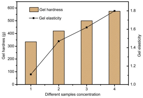
Figure 1.
The effects of different concentrations on the hardness and elasticity of the gel.
2.2. Design and Fabrication of Scaffolds
Firstly, the scaffold samples’ CAD model with a cuboid shape was constructed by Magics EnvisionTEC (Figure 2a), and then the model was sliced into 10 layers with the Bioplotter RP software [21]. VisualMachine software was utilized to control the printing and assign the print parameters for the model (Figure 2b), and then the gelatin–sodium alginate complex scaffold samples were fabricated using Bioplotter, which was manufactured by the German company Envision TEC (Figure 2c). Bioplotter is composed of a three-axis positioning system, an automatic tool conversion system, a linear ball bearing, a heating base plate with a vacuum fixing system, a high temperature resistant printing head and a low temperature resistant printing head. The device realized the transformation from CT scan data of patients to solid 3D biological scaffolds. The 3D-Bioplotterwas controlled by PC and monitored and operated by a workstation. The composite gel was used to fabricate scaffolds by printing the composite solution into the CaCl2 solution to induce crosslinking layer by layer. The alginate was dispensed at 37 °C using a conical needle with different inner diameters. After fabrication, the scaffolds were maintained in the crosslinking solution for a time period sufficient to allow the Ca2+ ions to penetrate and crosslink the whole structure.
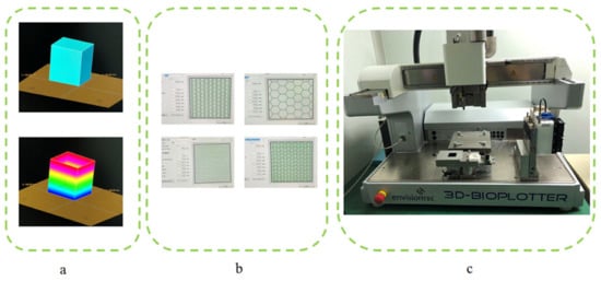
Figure 2.
Scaffold printing process. (a) CAD model construction and sliced layers generation; (b) Different pattern assigned before printing; (c) 3D-Bioplotter.
2.3. Extrusion Process Theory and Simulation Model of Printing Process
2.3.1. Extrusion Process Theory Model
For the fabrication of biological scaffolds, it is of significant importance to strictly select the parameters of needle movement speed, air pressure, fiber spacing, and temperature and so on. These changes affect the mechanical properties of scaffolds and the viability of implanted cells, such as line width and spacing, which influence the pore size and porosity of scaffolds, and thus affect the mechanical properties of scaffolds and the proliferation and attachment of binding cells in scaffolds. The cryogenic printing head can be simplified, as shown in Figure 3a. The sodium SA-GEL solution was pre-stored in the syringe. When pressure P was applied to the top of the needle, the composite materials were extruded from the needle. The Bioplotter was able to adjust the air pressure in the range of 0–5 Bar, and the diameter of the conical needle outlet was in the range of 0.2–1 mm. In Figure 3a(ii), P is the pressure applied to the needle of the biographical plotter, Pe is the outlet pressure of the needle end, r1 and r0 are the radius of the entry and exit of the needle respectively, θ is the half-cone angle. Because the diameter of the barrel was much larger than that of the conical needle, and the drop speed of the liquid level in the barrel was much lower than that of the fluid in the conical needle, the change in the liquid level height in the barrel was neglected. To further simplify the model, we made the following assumptions in a pneumatic distribution system:
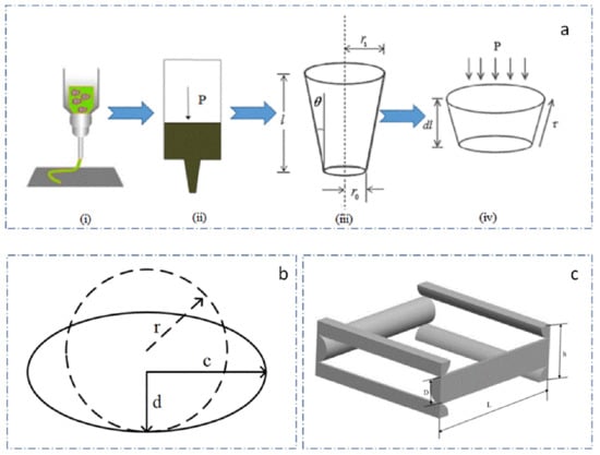
Figure 3.
The printing process model and the prediction model of scaffold porosity. (a) simplified model of printhead; (b) morphology change of extruded gel; (c) unit structure of scaffold.
- The composite solution was in-compressible.
- The flow of compound solution in needle was stable and fully developed.
- The slip between the composite solution and the needle wall was significant.
- The diameter of the barrel was much larger than that of the conical needle, so the pressure loss in the barrel could be neglected.
- The slight loss caused by the entrance effects and accessories could be neglected.
The pressure difference between the top and the outlet of the needle can be expressed as (1):
The tangent value of the θ can be expressed as (2):
The total flow equation of needle mixed solution can be written as (3):
where Q is total flow, Q1 is shear flow; Q2 is slip flow.
The force balance equation of the pressure and shear stress of a conical needle can be written as (4):
where: , .
Given that the effects of accelerated shear flow are ignored, the pressure difference can be calculated as (5):
Q1 and Q2 can be deduced from (6):
where Vslip is slip velocity, which can be expressed as (8):
where β is the slip layer thickness and τw is the shear stress on the needle wall. K is the coefficient of mixed solution consistency.
So, we can conclude the total flow equation of needle mixed solution as Equation (9):
The average speed of the needle extrusion prediction model can be concluded from (9):
Because of the effects of gravity, the composite gel will collapse on both sides, assuming that the section of the extruded line transforms from circular to elliptical, that its long diameter is c, the short diameter is d, the section change is as shown in Figure 3b, and the length of the columnar body is Lcd, can be written as:
where v is the needle movement speed and t is the needle movement time.
The volume of the cylindrical line extruded at a given time V can be expressed as (12):
where Kcd is the elliptic coefficients, .
So, we can obtain the prediction model of fiber width after extrusion in mixed solution, (13) expressed as:
where ΔP is the air pressure difference, r1 is the needle inlet radius, r2 is the needle outlet radius, v is the needle velocity, K is the consistency coefficient, θ is the angle between the needle wall and the vertical direction, and n is the flow coefficient.
The porosity of scaffolds is closely related to the mechanical properties of scaffolds. Meanwhile, it is also exceedingly important for cell growth, differentiation and proliferation. Porosity can be adjusted by changing the spacing, line width and layer height according to different printing targets. Fiber spacing is the most important factor. The scaffolds structure unit is shown in Figure 3c, without considering the influence of the edge structure of the scaffolds, the porosity of scaffolds can be regarded as the function of interval L, line width D and formation height H:
The volume of the micro-structural unit is:
The volume of the stent material is:
Therefore, the porosity of the scaffolds is:
From the Equation (11), we can obtain the prediction model of porosity of printing scaffold structure as Equation (18), which can guide us to set optimal parameters to get corresponding porosity of scaffold.
2.3.2. Extrusion Process Simulation Model
The scaffold printing process was simulated and analyzed by using Fluent, and the relationships among the variables in the model were explored. The flow coefficient n of the composite solution was set to 0.5 and the consistency coefficient K was set to 18.5. In this paper, needles r2 of 2.5 mm, and r0 of 0.2 mm and the length L is 30 mm, were selected. θ was nearly 4 degrees, and the slip layer thickness approximated 9.9 μm, and Kcd was set to 0.8. By introducing these parameters, the simulation model of extrusion process could be constructed, as shown in Figure 4.
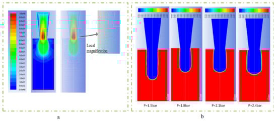
Figure 4.
The extrusion process simulation model. (a) flow velocity distribution simulation; (b) different expansion under different pressure conditions.
Pressure and platform movement speed are also important factors which affect the line width of the printing material. At the same time, air pressure also determines the flow of extruded gel, so the pressure and velocity were selected as variables to explore its effect on line width. In order to obtain different extrusion flow rates, 1.2 bar, 1.5 bar, 1.8 bar, 2.1 bar and 2.4 bar were selected as pressure variables to compare the line width of the needle in the range of 0–20 mm/s. As shown in Figure 5, as the pressure and movement increased, the line width narrowed quickly. When the pressure increased to above 2.4 bar and the movement speed increased to above 20 mm/s, the line width became stable. From the dotted line of 0.4 mm red contour line in Figure 5, it can be seen that the needle moving speed of the optimum linewidth (the same linewidth as the inner diameter of the conical needle outlet) was different under different pressure variables, which were 4.77 mm/s, 7.45 mm/s, 10.73 mm/s, 14.6 mm/s and 19.08 mm/s, respectively, which were all higher than the extrusion flow velocity under their respective pressures and conformed to the mathematical model of the linewidth prediction. When printing, the speed could be set to the needle speed corresponding to different pressure variables to obtain the optimal linewidth. Under the same pressure variable, too fast and too slow needle movement would lead to problems such as stretching and material accumulation, which would seriously affect the accuracy and formability of extrusion lines. To sum up, it was more appropriate to choose the needle moving speed between 10 and 16 mm/s by linear width mathematical model (13).
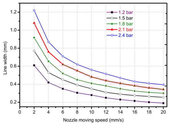
Figure 5.
The line width with different nozzle moving in different pressures and moving speeds.
For extrusion lines with the same line width, the porosity of scaffolds varied with different fiber spacing. Setting the fiber interval in the range of 0.4–4 mm, other variables are maintained unchanged to simulate the printing conditions and parameters. Using a conical needle with an outlet diameter of 0.4 mm and setting the pressure of 1.8 bar and the needle speed of 10.7 mm/s, the relationship between the porosity of the scaffold and the fiber interval was obtained, as shown in Figure 6.
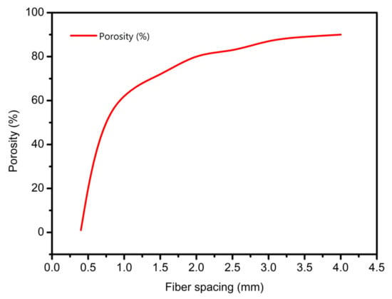
Figure 6.
The prediction relationship curves of different fiber spacings with porosity.
As shown in Figure 6, the larger the fiber spacing, the larger the porosity of the scaffold. When the fiber interval was less than 0.4 mm, the porosity of the scaffold was zero or even negative, and the scaffold accumulation was serious. In addition, when the interval was small, a slight change made the size of the scaffold porosity fluctuate greatly. When the interval was set to 1 mm, the porosity was about 60%. When the porosity interval needed to be greater than 60%, it needed to be greater than 1 mm. According to the requirement of cell growth on scaffold pore; the interval can be between 1–1.5 mm.
3. Results and Discussion
To investigate the effectiveness and corrective capability of the predicted model, we printed different samples as Section 2.3.1 discusses. To obtain successive samples, there was some preparation we needed to do, as follows:
- Suppression bubbles of printing materials—the continuity of the extrusion line is very important for the accuracy and forming effects of the scaffold [22]. In the preparation of SA-GEL composite material, bubbles will be introduced due to mixing and other factors. The bubbles in the material will affect the continuity of extrusion, and the break point will affect the mechanical properties of scaffolds. Accordingly, bubbles in the barrel solution should be cleaned. In this paper, a static suppression method was used to solve the problem—the cylinder filled with composite solution was heated upside down until the bubbles in the material could not be observed by naked eyes.
- Selection of printing platforms—unlike Fused Deposition Molding (FDM) method, the SA-GEL composite materials used in this paper had a large amount of water, so it was indispensable to select appropriate deposition platforms [23]. Hydrophobicity is the main index for selecting deposition platforms. The platform made of hydrophobic materials, such as plastic containers, shrinks the complex gel deposited on the hydrophobic platform to form a globule, which seriously affects the forming of scaffolds. When the gel is deposited on the platform made of hydrophilic materials, problem of excessive deposition will occur. Therefore, after many experiments, PS film was chosen as the deposition platform [24]. Due to the differences between hydrophilic and hydrophobic materials, the deposition and diffusion of hydrogels on PS film are not obvious. In addition, adhesion of the gel on the PS film can overcome surface tension, so that the shrinkage does not occur.
- Calcium chloride assisted stereotyping—in the process of printing, the calcium chloride solution was used to semi-crosslink atomically with the deposited composite SA-GEL. As a result, not only the curing process, but also the shaping effects of scaffolds could be improved [25].
- Selection of the diameter of conical needle—as the diameter of conical needle increased, the required air pressure decreased, and the needle speed needed to be accelerated. At the same time, when the pressure was low, cells in the composite materials received less damage due to extrusion. The acceleration of the needle movement reduced the printing time of the scaffold and improves preparation efficiency. With the increase of conical needle diameter, the porosity of the printing scaffold decreased gradually [26]. Additionally, considering that the diameter of tissue cells varies from more than ten microns to tens of microns, the outlet diameter was 0.4 mm to print the scaffold.
From the prediction model of fiber width and porosity of scaffold, printing pressure, needle moving speed and spacing are key factors affecting scaffolds forming.
3.1. Pressure Affective Analysis
The printing pressure was assigned as 1 bar, 1.5 bar, 2.5 bar, 3, bar, 3.5 bar, and 4 bar, respectively. The total mass of the composite solution was measured within 1 min, and then divided by the density and time of the solution. The relationship between flow rate and pressure was obtained, as shown in Figure 7. The flow rate increases exponentially with the increase of air pressure, indicating that the flow coefficient n is not 1, and the composite material is proved to be a non-Newtonian pseudoplastic fluid. The experimental data fit the theoretical value curve well, which proves the necessity of considering the slip effect, and also shows that the flow forecasting model is correct. The experimental results under the conditions of 1.5 bar, 1.8 bar, 2.1 bar and 2.4 bar show that the extrusion diameter at 1.8 bar pressure is less affected by the extrusion swell and the continuous forming ability is stronger, as shown in Figure 8.
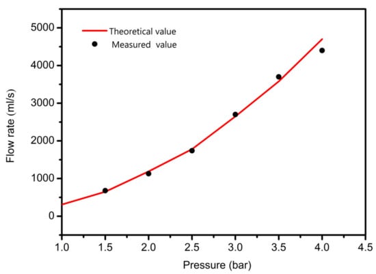
Figure 7.
The relationship between the flow and pressure.
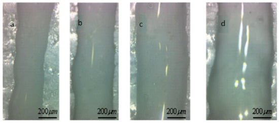
Figure 8.
Extrusion line form at different pressure. (a) extrusion line with the feeding pressure is 1.5 bar; (b) extrusion line with the feeding pressure is 1.8 bar; (c) extrusion line with the feeding pressure is 2.1 bar; (d) extrusion line with the feeding pressure is 2.4 bar.
3.2. Needle Moving Speed Affective Analysis
In order to study the influence of the needle moving speed on the printing accuracy, the extrusion pressure was set to 1.8 bar, and the sprinkler moving speed was set to 4, 7, 10, 13, 16 mm/s, respectively. The sprinkler was printed by 0–90 degree lying and the height of the adjacent two layers was set to 0.32 mm. A digital microscope was used to observe the printing support at different moving speeds; the results are shown in Figure 9.
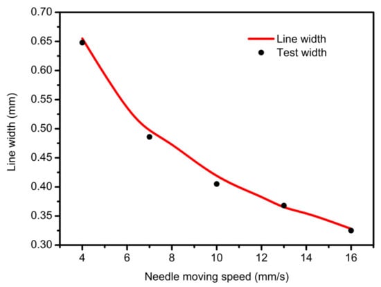
Figure 9.
The relationship between the nozzle moving speed and line width.
When the needle velocity is too low (v = 4 mm/s, 6 mm/s), the well-shaped structure of the support is submerged, and the pore becomes smaller or even blocked, as shown in Figure 10a,b. With the acceleration of the needle speed, the width of the extrusion line keeps decreasing, approaching the optimal inner diameter when v equals to 10 mm/s or 13 mm/s, as shown in Figure 10c,d. However, when the moving speed is too fast for the gel extrusion speed to keep up with, it will cause shrinkage or even fracturing of the fiber, which will affect the accuracy and mechanical properties of the bracket, as shown in Figure 10e,f.
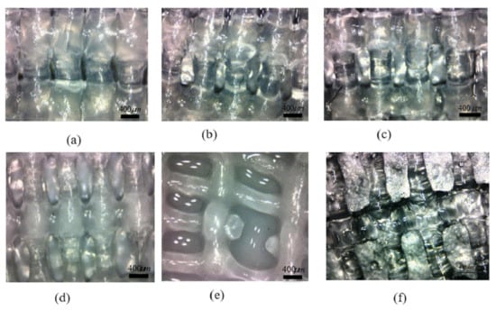
Figure 10.
Micro-view of midline of scaffold at different moving speeds. (a) extrusion line with moving speed 4 mm/s; (b) extrusion line with moving speed 7 mm/s; (c) extrusion line with moving speed 10mm/s; (d) extrusion line with moving speed 13 mm/s; (e) extrusion line with moving speed 16 mm/s; (f) extrusion line with moving speed 20 mm/s.
3.3. Scaffolds Porosity Affective Analysis
Porosity is a crucial index for evaluating scaffolds [27]. The size of porosity determines the growth ability and mechanical properties of cells, while the porosity of scaffolds mainly depends on fiber spacing. On the premise of guaranteeing the quality and mechanical properties of the support, the main purpose of this section is to adjust the size of the porosity by changing the line spacing; the results are shown in Figure 11.
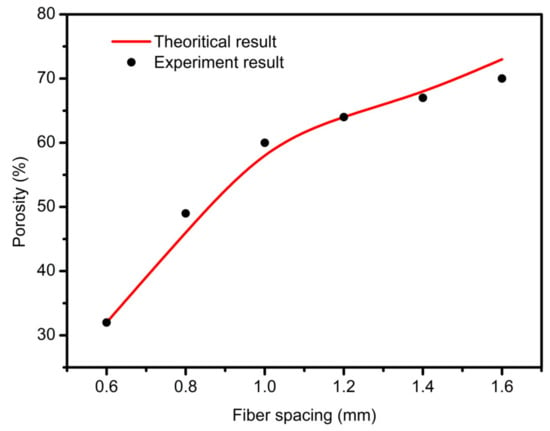
Figure 11.
The relationship between fiber spacing and porosity.
The printing parameters were set as follows: air pressure 1.8 bar, needle outlet diameter 400 um, needle speed 10.7 mm/s, thickness 0.32 mm. When the fiber spacing is too small, as shown in Figure 12a, the gap between the extrusion lines is very small, and even sticks together because of the swelling effects. After cross-linking, the pore structure becomes even smaller, and some are even blocked. The permeability of the scaffold structure decreases, which is not conducive to cell growth. When the fiber spacing is appropriate, as shown in Figure 12b–d, there is a certain gap among the extrusion lines deposited on the substrate, which can form a better pore structure. On this basis, the printed support has good permeability and a high mechanical strength. When the interval between fibers is too large, the lower layer cannot provide enough support force to the next layer, so the collapse occurs. With an increase in the number of printing layers, the collapse phenomenon becomes more serious. The z-axis direction pore is completely blocked, which reduces the overall structural strength of the support. This phenomenon occurs in some areas of Figure 12e-f.
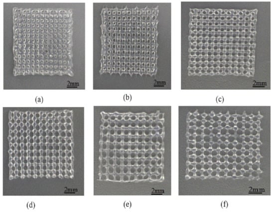
Figure 12.
Print scaffolds at different intervals. (a) scaffold structure with fiber spacing 0.6 mm; (b) scaffold structure with fiber spacing 0.8 mm; (c) scaffold structure with fiber spacing 1.0 mm; (d) scaffold structure with fiber spacing 1.2 mm; (e) Scaffold structure with fiber spacing 1.4 mm; (f) Scaffold structure with fiber spacing 1.6 mm.
The porosity of scaffolds was measured by the liquid displacement method [28]. The specific test methods were as follows: using electronic balance to weigh the specific gravity bottle filled with ethanol, the quality was Z1; weighing the composite support after freeze-drying, the quality was Z2; putting the composite support after freeze-drying into the specific gravity bottle, adding ethanol to make it filled with the specific gravity bottle and weighing, the quality was Z3: using tweezers to remove the support (the pore of the support is filled with ethanol) from the bottle, weighing the specific gravity bottle after removing the support (there is residual ethanol in the bottle), the quality was Z4.
The porosity Z of the scaffold is as following:
The theoretical porosity can be calculated by using the foregoing mathematical model of porosity prediction, and the theoretical value of porosity can be compared with the experimental data, as shown in Table 3.
Table 3.
The theoretical porosity and the measured porosity of scaffolds.
Table 3 shows that when the fibers are spaced in the range of 0.6–1.4 mm, the theoretical and the measured porosity are basically the same. Scaffolds with 50–70% porosity can be printed out, and the porosity is very neat, which confirms the correctness of the related mathematical model. However, when the interval is 1.4 mm or more, the collapse of fibers occurs in some areas of the scaffolds. The actual porosity is slightly less than the theoretical one; the mechanical properties of the scaffolds are poor, and there are discontinuous pore structures in the scaffolds. Considering the spacing between 1–1.4 mm and the porosity between 60–82%, it is advantageous to cell culture.
3.4. Scaffolds Mechanical Properties Analysis
A shared drawback of porous hydrogel scaffolds is their relatively weak mechanical properties. By adjusting the proper internal structures, the mechanical properties of scaffolds can be improved [25]. The essence is to change the contact area between two adjacent layers by adjusting the different angles of extruded gel, thereby obtaining a different Young’s modulus and dynamic modulus of scaffolds. In this paper, the SA-GEL solution made from 3% sodium alginate and 8% gelatin was selected and the printing parameters were set as the extrusion pressure being 1.8 bars, the moving speed of the nozzle being 10 mm/s, and the layer height being 0.32 mm. Not only were the 0–90 degree scaffolds with 1 and 1.2 mm spacing printed, but also the scaffolds with internal 0/45/135 degrees and 0/45 degrees were printed. The printed paths were just as Figure 13 shows—the scaffold in Figure 13a was a 0/90 degree scaffold with 1 mm spacing, the scaffold in Figure 13b was a 0/90 degree scaffold with 1.2 mm spacing, the scaffold in Figure 13c was a 0/45 degree scaffold with 1.2 mm spacing, the scaffold in Figure 13d was a 0/45/135 degree scaffold with 1.2 mm spacing, and the scaffold in Figure 13e was a staggered scaffold with 1.2 mm spacing. The size of sample model is (12 x 12 x 3) mm3 for each condition.
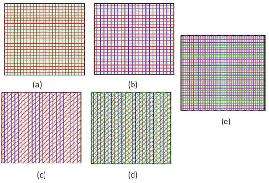
Figure 13.
Different internal structure patterns of scaffolds. (a) 0/90 degree scaffolds with 1 mm spacing; (b) 0/90 degree scaffolds with 1.2 mm spacing; (c) 0/45 degree scaffolds with 1.2 mm spacing; (d) 0/45/135 degree scaffolds with 1.2 mm spacing; (e) staggered scaffolds with 1.2 mm spacing.
The printing results are shown in Figure 14, which are all highly consistent with the predictions of the theoretical model. Then, the mechanical properties of hydrogel scaffolds cross-linked with different internal structures were studied, including Young’s modulus and the dynamic modulus.
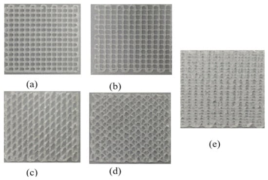
Figure 14.
The printing results with different internal structure patterns. (a) printed result with 0/90 degree scaffolds with 1 mm spacing; (b) printed result with 0/90 degree scaffolds with 1.2 mm spacing; (c) printed result with 0/45 degree scaffolds with 1.2 mm spacing; (d) printed result with 0/45/135 degree scaffolds with 1.2 mm spacing; (e) printed result with staggered scaffolds with 1.2 mm spacing.
Scaffolds with different internal structures were tested as follows: the compressive modulus of the scaffolds was measured by the cross-head velocity of 0.01 m/s, and the Young’s modulus was calculated based on the linear region of the stress–strain curves of all the samples. The dynamic test was carried out by applying 15% sinusoidal deformation at a frequency of 1 Hz. After more than 20 cycles of steady-state response, the dynamic modulus was determined from the ratio of stress amplitude to strain amplitude. Under the condition of 50% deformation, a 24-h creep recovery test was carried out in PBS at 37 °C, and the stress was removed, and the samples were allowed to recover within 24 h.
It can be clearly seen from Figure 15 and Figure 16 that the scaffold with an internal structure of 0/90 is the group with the smallest middle distance of all scaffolds. The Young’s modulus is the highest, reaching 113.64 ± 12.83 KPa, and the dynamic modulus is also the highest, at 841.5 ± 27.9 KPa, but the porosity of the scaffolds is the lowest. When the fiber spacing increases to 1.2 mm, just make the internal structure as 0/90 degree with 1.2 mm spacing; the Young’s and dynamic moduli of samples were 69.7 ± 4.5 KPa and 502.3 ± 63.5 KPa, respectively, which decreased significantly. Larger fiber spacing reduces the mechanical properties of the scaffolds, which is in line with the expected relationship between fiber spacing, porosity and mechanical properties of the composite scaffolds. That is, the larger the fiber spacing is, the higher the porosity is, and the worse the mechanical properties of the scaffolds are. When the internal structure of the scaffold was 0/45-1.2, the Young’s and dynamic moduli were 86.6 ± 10 KPa and 671.4 ± 31 KPa, respectively, which were significantly higher than those of the 0/90-1.2 scaffold group with the same fiber spacing. This may be because the scaffold designed at angle 0/45 provides more contact areas among adjacent layers. As shown in Figure 17a,b, the area of (a) is D2, while the area of (b) is (2D2)1/2, which provides more mechanical strength. When the internal structure of the scaffold is 0/45/135-1.2, the direction of the fiber lines in the adjacent layers will change continuously, which will further reduce the effective contact area, as shown in Figure 17c, thus weakening the mechanical properties of the scaffold.
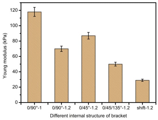
Figure 15.
Young’s modulus diagram of scaffolds with different internal structures.
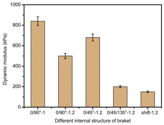
Figure 16.
Dynamic modulus diagrams of scaffolds with different internal structures.
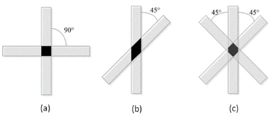
Figure 17.
Contact area of adjacent layers with different internal structures. (a) 0/90 degree internal structure; (b) 0/45 degree internal structure; (c) 0/45/135 degree internal structure.
When the spatial distribution of extruded fibers (displacement group) was changed, the mechanical modulus of displaced scaffold was worse than that of 0/90-1.2 of displaced scaffold. This shows that the relative position of the extruded fibers in each layer also has a significant impact on the mechanical properties of the scaffolds. The mechanical strength of displaced scaffolds is the worst among all scaffolds, with the lowest Young’s modulus of 30.4 ± 9 KPa and a dynamic modulus of 153.3 ± 15 KPa, which may be related to the structure of displacement. At the same time, due to its unique displacement structure, the strain effect is largely offset and absorbed by the deformation of internal pores. It is worth noting that the compression modulus of each bracket group is much lower than that of the physiological load frequency. This fact indicates that the static modulus alone is not enough to reflect the functional response of the composite gel. This discovery can guide the research direction regarding the mechanical properties of printing supports and is exceedingly meaningful.
3.5. Scaffold Biocompatibility Test
After disinfecting and treating the scaffold surface, the C5.18 chondrocytes cells were implanted on the scaffold surface and cultured for a long time. The cells were stained alive/dead on Day 1, 5 and 7, respectively. The cells were marked by green fluorescence for live cells and marked by red for dead cells. As shown in Figure 18, the results indicate that the cells would survive well. On the first day of chondrocyte culture, the cells adhered to the composite hydrogel scaffolds. With the increase in culture days, the cells grew better, because the cell culture medium and the metabolic waste liquid can flow smoothly in the gap structure of the scaffold. At the same time, the high porosity also increases the surface area of the scaffold, which provides more places for cell growth and proliferation. Under the scanning electron microscope, as shown in Figure 19, it can be clearly seen that when the chondrocytes are cultured in vitro for one week, they adhere closely to the scaffold, and some of them are extending pseudopodia, which have been marked with a red circle line, and seem to have extracellular matrix secretion.
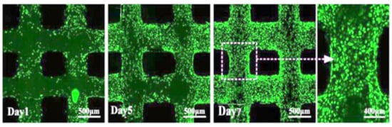
Figure 18.
Cell viability and distribution in the scaffold designs (green for living cells, red for dead cells).
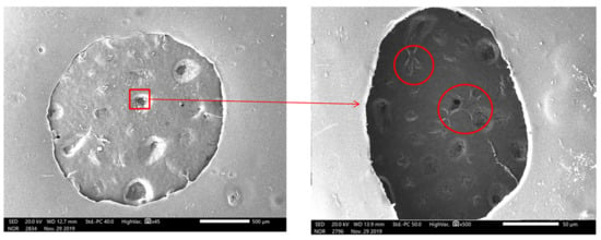
Figure 19.
Scanning electron microscopic observations of chondrocytes cultured on scaffold (x45 and X500).
The C5.18 cell viability on the scaffolds surfaces was analyzed. As in Figure 20, the survival rate was 93.9% on the first day, 97.3% on the fifth day, and 98.2% on the seventh day, indicating that the cells could exchange substances within the scaffolds, so the death rate was very low. The above data show that the composite hydrogel scaffolds have good biocompatibility.
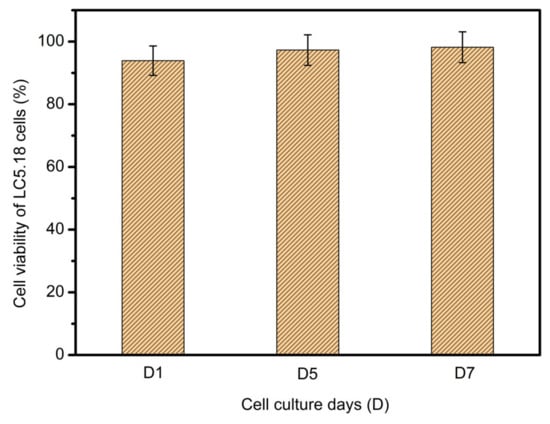
Figure 20.
Cellular viability of LC5.18 cells on scaffold surface after one-day, five-day and seven-day cultures.
4. Conclusions
- The SA-GEL printing material was prepared. The properties of SA-GEL composite material under various ratios were analyzed from viscosity tests and mechanical performance. The optimum material ratio (sodium alginate:gelatin = 3:8) was determined by comprehensive evaluation.
- Modeling and simulation analysis of gel material extrusion process. First of all, the rheological properties of gel materials were analyzed, and then the cone needle model was simplified. Considering the slip effects, the mathematical model of extrusion flow was established from two facets of shear flow and slip flow. Finally, the printing line width and porosity prediction model was obtained, and the pressure and needle movement were analyzed by fluent simulation software. The variation law of flow rate, line width and porosity of support is affected by velocity and other factors.
- In study of pressure, the flow model and fluent expansion simulation were validated by the measurement of extrusion flow rate and the experiment of extrusion swell. Then the needle speed of 10.7 mm/s was selected from the influence of needle speed on stent size and line width. In the analysis of fiber spacing, it was found that the mechanical strength of scaffolds was not enough when the spacing was too large, and the cells could not grow well when the spacing was too small, and the interval of porosity and mechanical strength was 1–1.4 mm. In the analysis of influence factors about different internal scaffold structure, by adjusting the proper internal structures, mechanical properties of scaffolds can be improved, when the internal structure of the scaffold was 0/45-1.2, the Young’s and dynamic modulus were 86.6 ± 10 KPa and 671.4 ± 31 KPa respectively, which has good mechanical property.
- C5.18 osteoblasts cells were implanted on the scaffold surface and cultured; the results indicate that the cells would survive well.
- Finally, the performance of the printed composite SA-GEL scaffolds was tested and analyzed. The mechanical properties of the bracket show that the mechanical performance of the bracket is mainly affected by the porosity, the contact area between the extruded fiber lines and the relative position of the extruded lines. These experimental results support the original simulation that, under the control of printing parameters such as a temperature of 37 C°, pressure of 1.8 bar, moving speed of 10.7 mm/s and an interval of 1.2 mm, better scaffold printing results can be obtained for newly prepared sodium alginate–gelatin composite bio-printing materials.
Author Contributions
Conceptualization, Y.G. and M.S.H.A.-F.; Data curation, F.W., Z.B., J.H., W.L. and G.C.; Formal analysis, Y.G., F.W., X.B. and H.L.; Funding acquisition, Y.G., H.S. and G.C.; Investigation, M.S.H.A-F, L.S. and J.H.; Methodology, Y.G., M.S.H.A.-F., X.B. and W.L.; Project administration, Y.G.; Resources, F.W., L.S. and W.L.; Software, Y.G., F.W., L.S., Z.B. and J.H.; Supervision, Y.G. and M.S.H.A.-F.; Validation, X.B., H.L. and A.B.S.; Writing—Original draft, Y.G., F.W., X.B. and H.S.; Writing—Review & editing, M.S.H.A.-F. All authors have read and agreed to the published version of the manuscript.
Funding
The work is financially supported by the National Natural Science Foundation of China (51805475, 51675148, 51275141, 51305113), Key Discipline of The Ocean Techtronic Equipment’s Technology, Nature Science Foundation of Zhejiang Provinces Technology 101, 51475129, 3D assembly of complex biological structure (LY14E050026), Zhejiang Province Higher Visiting Scholar project Technology 101, 51475129, Malaysia’s Ministry of Higher Education (DIP-2017-001), and Outstanding Young Teachers Fund of Hangzhou Dianzi University (GK160203201002/003).
Conflicts of Interest
The authors declare no conflicts of interest.
References
- Simon, T.M.; Jackson, D.W. Articular cartilage: Injury pathways and treatment options. Sports Med. Arthrosc. Rev. 2018, 26, 31–39. [Google Scholar] [CrossRef]
- Brophy, R.H.; Zeltser, D.; Wright, R.W.; Flanigan, D. Anterior Cruciate Ligament Reconstruction and Concomitant Articular Cartil. Injury: Incidence and Treatment. Arthrosc. J. Arthrosc. Relat. Surg. 2010, 26, 112–120. [Google Scholar] [CrossRef]
- Jones, H.R.; Crawford, D.C. An autologous tissue implant, NeoCart, for treatment of hyaline cartilage injury in the knee. Oper. Tech. Orthop. 2014, 24, 264–270. [Google Scholar] [CrossRef]
- Shi, W.; Sun, M.; Hu, X.; Ren, B.; Cheng, J.; Li, C.; Duan, X.; Fu, X.; Zhang, J.; Chen, H. Structurally and functionally optimized silk-fibroin–gelatin scaffold using 3D printing to repair cartilage injury in vitro and in vivo. Adv. Mater. 2017, 29, 1701089. [Google Scholar] [CrossRef] [PubMed]
- Jung, A.; Makkar, P.; Amirian, J.; Lee, B.-T. A novel hybrid multichannel biphasic calcium phosphate granule-based composite scaffold for cartilage tissue regeneration. J. Biomater. Appl. 2018, 32, 775–787. [Google Scholar] [CrossRef] [PubMed]
- Uz, U.; Gunhan, K.; Vatansever, S.; Kivanc, M.; Yuceturk, A.V. Novel Simple Strategy for Cartilage Tissue Engineering Using Stem Cells and Synthetic Polymer Scaffold. J. Craniofacial Surg. 2019, 30, 940–943. [Google Scholar] [CrossRef] [PubMed]
- Bryant, S.J.; Anseth, K.S. The effects of scaffold thickness on tissue engineered cartilage in photocrosslinked poly (ethylene oxide) hydrogels. Biomaterials 2001, 22, 619–626. [Google Scholar] [CrossRef]
- Filardo, G.; Kon, E.; Roffi, A.; Di Martino, A.; Marcacci, M. Scaffold-based repair for cartilage healing: A systematic review and technical note. Arthrosc. J. Arthrosc. Relat. Surg. 2013, 29, 174–186. [Google Scholar] [CrossRef]
- Nettles, D.L.; Elder, S.H.; Gilbert, J.A. Potential use of chitosan as a cell scaffold material for cartilage tissue engineering. Tissue Eng. 2002, 8, 1009–1016. [Google Scholar] [CrossRef]
- Zhu, W.; Cui, J.; Duan, L.; Chen, J.; Zeng, Y.; Wang, D. Research progress of scaffold materials in cartilage tissue engineering. J. Biomater. Tissue Eng. 2015, 5, 673–679. [Google Scholar] [CrossRef]
- Balakrishnan, B.; Joshi, N.; Jayakrishnan, A.; Banerjee, R. Self-crosslinked oxidized alginate/gelatin hydrogel as injectable, adhesive biomimetic scaffolds for cartilage regeneration. Acta Biomater. 2014, 10, 3650–3663. [Google Scholar] [CrossRef] [PubMed]
- Gao, F.; Xu, Z.; Liang, Q.; Liu, B.; Li, H.; Wu, Y.; Zhang, Y.; Lin, Z.; Wu, M.; Ruan, C. Direct 3D printing of high strength biohybrid gradient hydrogel scaffolds for efficient repair of osteochondral defect. Adv. Funct. Mater. 2018, 28, 1706644. [Google Scholar] [CrossRef]
- Wang, Z.; Zhang, J.; Zhang, Q.; Gao, Y.; Yan, J.; Zhao, X.; Yang, Y.; Kong, D.; Zhao, J.; Shi, Y. Evaluation of bone matrix gelatin/fibrin glue and chitosan/gelatin composite scaffolds for cartilage tissue engineering. Genet. Mol. Res. 2016, 15, 1–8. [Google Scholar] [CrossRef] [PubMed]
- Ito, A.; Mase, A.; Takizawa, Y.; Shinkai, M.; Honda, H.; Hata, K.-I.; Ueda, M.; Kobayashi, T. Transglutaminase-mediated gelatin matrices incorporating cell adhesion factors as a biomaterial for tissue engineering. J. Biosci. Bioeng. 2003, 95, 196–199. [Google Scholar] [CrossRef]
- Fassina, L.; Saino, E.; Visai, L.; Avanzini, M.A.; De Angelis, M.G.C.; Benazzo, F.; Van Vlierberghe, S.; Dubruel, P.; Magenes, G. Use of a Gelatin Cryogel as Biomaterial Scaffold in the Differentiation Process of Human Bone Marrow Stromal Cells. In Proceedings of the 2010 Annual International Conference of the IEEE Engineering in Medicine and Biology, Buenos Aires, Argentina, 31 August–4 September 2010; pp. 247–250. [Google Scholar]
- Loth, T.; Hötzel, R.; Kascholke, C.; Anderegg, U.; Schulz-Siegmund, M.; Hacker, M.C. Gelatin-based biomaterial engineering with anhydride-containing oligomeric cross-linkers. Biomacromolecules 2014, 15, 2104–2118. [Google Scholar] [CrossRef]
- Chang, C.H.; Liu, H.C.; Lin, C.C.; Chou, C.H.; Lin, F.H. Gelatin–chondroitin–hyaluronan tri-copolymer scaffold for cartilage tissue engineering. Biomaterials 2003, 24, 4853–4858. [Google Scholar] [CrossRef]
- Chen, C.-H.; Chen, J.-P.; Lee, M.-Y. Effects of gelatin modification on rapid prototyping PCL scaffolds for cartilage engineering. J. Mech. Med. Biol. 2011, 11, 993–1002. [Google Scholar] [CrossRef]
- Ramadoss, P.; Arul, K.T.; Ramya, J.R.; Begam, M.R.; Chandra, V.S.; Manikandan, E. Enhanced mechanical strength and sustained drug release of gelatin/keratin scaffolds. Mater. Lett. 2017, 186, 109–112. [Google Scholar] [CrossRef]
- Li, Y.; Jia, H.; Cheng, Q.; Pan, F.; Jiang, Z. Sodium alginate–gelatin polyelectrolyte complex membranes with both high water vapor permeance and high permselectivity. J. Membr. Sci. 2011, 375, 304–312. [Google Scholar] [CrossRef]
- Sarker, M.; Chen, X. Modeling the flow behavior and flow rate of medium viscosity alginate for scaffold fabrication with a three-dimensional bioplotter. J. Manuf. Sci. Eng. 2017, 139, 081002. [Google Scholar] [CrossRef]
- Tai, H.; Mather, M.L.; Howard, D.; Wang, W.; White, L.J.; Crowe, J.A.; Morgan, S.P.; Chandra, A.; Williams, D.J.; Howdle, S.M. Control of pore size and structure of tissue engineering scaffolds produced by supercritical fluid processing. Eur. Cell Mater. 2007, 14, 64–77. [Google Scholar] [CrossRef] [PubMed]
- Kang, H.G.; Kim, S.Y.; Lee, Y.M. Novel porous gelatin scaffolds by overrun/particle leaching process for tissue engineering applications. J. Biomed. Mater. Res. Part B Appl. Biomater. 2006, 79, 388–397. [Google Scholar] [CrossRef] [PubMed]
- Gummalla, M.; Tsapatsis, M.; Watkins, J.; Vlachos, D. Multiscale hybrid modeling of film deposition within porous substrates. AIChE J. 2004, 50, 684–695. [Google Scholar] [CrossRef]
- Yunoki, S.; Ikoma, T.; Tanaka, J. Development of collagen condensation method to improve mechanical strength of tissue engineering scaffolds. Mater. Charact. 2010, 61, 907–911. [Google Scholar] [CrossRef]
- Erisken, C.; Zhang, X.; Moffat, K.L.; Levine, W.N.; Lu, H.H. Scaffold fiber diameter regulates human tendon fibroblast growth and differentiation. Tissue Eng. Part A 2012, 19, 519–528. [Google Scholar] [CrossRef]
- Arul, K.A.; Rashia, B.S.; Arumaikkannu, G. Investigation of Porosity Relationship in Additive Manufactured Novel Bone Scaffold. In Applied Mechanics and Materials; Trans Tech Publications: Zurich, Switzerland, 2014; Volume 592, pp. 836–841. [Google Scholar]
- Li, J.; Wang, Q.; Gu, Y.; Zhu, Y.; Chen, L.; Chen, Y. Production of composite scaffold containing silk fibroin, chitosan, and gelatin for 3D cell culture and bone tissue regeneration. Med. Sci. Monit. Int. Med. J. Exp. Clin. Res. 2017, 23, 5311. [Google Scholar] [CrossRef]
© 2020 by the authors. Licensee MDPI, Basel, Switzerland. This article is an open access article distributed under the terms and conditions of the Creative Commons Attribution (CC BY) license (http://creativecommons.org/licenses/by/4.0/).