Article

Comparison between Occlusal Errors of Single Posterior Crowns Adjusted Using Patient Specific Motion or Conventional Methods

1
Department of Prosthodontics, College of Dentistry, Yonsei University, Yonsei-ro 50-1, Seodaemun-gu, Seoul 03722, Korea
2
Department of Oral and Maxillofacial Surgery, Yonsei University Wonju College of Medicine, Wonju 26426, Korea
3
Department of Conservative Dentistry, College of Dentistry, Yonsei University, Yonsei-ro 50-1, Seodaemun-gu, Seoul 03722, Korea
4
Department of Prosthodontics, Veterans Health Service Medical Center, 53 Jinhwangdo-ro 61-gil, Gangdong-gu, Seoul 05368, Korea
*
Authors to whom correspondence should be addressed.
Appl. Sci. 2020, 10(24), 9140; https://doi.org/10.3390/app10249140
Submission received: 30 November 2020 / Revised: 15 December 2020 / Accepted: 18 December 2020 / Published: 21 December 2020
(This article belongs to the Special Issue Advances in Dental Materials: A Look inside Digital Workflows)

Abstract

:
Recently, digital technology has been used in dentistry to enhance accuracy and to reduce operative time. Due to advances in digital technology, the integration of individual mandibular motion into the mapping of the occlusal surface is being attempted. The Patient Specific Motion (PSM) is one such method. However, it is not clear whether the occlusal design that is adjusted using PSM could clinically show reduced occlusal error compared to conventional methods based on static occlusion. In this clinical comparative study including fifteen patients with a single posterior zirconia crown treatment, the occlusal surface after a clinical adjustment was compared to no adjustment (NA; design based on static occlusion), PSM (adjusted using PSM), and adjustment using a semi-adjustable articulator (SA) for the assessment of occlusal error. The root mean square (RMS; μm), average deviation value (±AVG; μm), and proportion inside the tolerance (in Tol; %) were calculated using the entire, subdivided occlusal surface and the out of tolerance area. Using a one-way ANOVA, the RMS and +AVG from the out of tolerance area showed a statistical difference between PSM (202.3 ± 39.8 for RMS, 173.1 ± 31.3 for +AVG) and NA (257.0 ± 73.9 for RMS, 210.9 ± 48.6 for +AVG). For the entire and subdivided occlusal surfaces, there were no significant differences. In the color-coded map analysis, PSM demonstrated a reduced occlusal error compared to NA. In conclusion, adjustment occlusal design using PSM is a simple and effective method for reducing occlusal errors that are difficult to identify in a current computer-aided design (CAD) workflow with static occlusion.

1. Introduction

The design of a single crown restoration should be in a functionally and anatomically harmonic relationship with the adjacent and antagonistic teeth [1,2,3,4,5]. The occlusal surface of a single crown should offer functional stability in maximum intercuspation (MICP) and no interference during eccentric movements [6]. Conventional single-crown restorations are designed and adjusted in a dental laboratory using various mechanical articulators, which are used for harmonious occlusal relationships [7]. Conventional mechanical articulators have long been successfully and effectively used for diagnostic and therapeutic treatments in dentistry [8,9,10,11]. Using a conventional articulator, it is possible to reproduce the anatomical relationship and simulate mandibular movement in an extraoral condition [12]. Therefore, this mechanical device is a valuable and practical tool for various treatments that are available from the fabrication of simple restoration to complex oral rehabilitation [8,13]. However, conventional articulators mainly focus on reproducing the mechanical maxilla-mandible relationship rather than reconstructing the mandibular functional movement [14]. Even a fully adjustable articulator cannot exactly duplicate functional mandibular movement [15]; the design of fully functional occlusion through conventional methods is not possible. The traditional solution to this problem is a clinical occlusal adjustment for harmonious occlusion, which corresponds to an individual’s functional movement [7]. For a more accurate reconstruction of the occlusal pathway, the functional generated pathway (FGP) technique was introduced by Myer et al. [16]. This technique includes recording the actual occlusal path during functional movement in the patient’s mouth where a recording medium is placed between arches. The clinical usefulness of this technique for fixed partial dentures was established [17,18,19]. However, the limitation of this technique is that the clinical procedure is complicated and additional laboratory work is required. In addition, it is controversial whether the recording material decreases the accuracy of the occlusal grid in which the accumulated occlusal movement is recorded [19].
In recent years, digital dental technology, such as computer-aided design (CAD) software and scanning equipment, has been widely used in dentistry to increase accuracy and reduce patient in-chair time [20]. The advance of intraoral scanners (IOSs) and CAD software has made virtual design workflow possible without conventional impression-taking and wax-up procedures [21]. However, the current digital workflow for occlusal design is based on static occlusion [22,23,24]. Although a virtual articulator module can be utilized for the refinement of occlusal design, because the fundamental mechanism between a virtual articulator and a mechanical articulator is similar, a complete reproduction of mandibular functional movement is not possible [25]. Therefore, time-consuming clinical adjustment is still required to remove interference caused by an incomplete occlusal reproduction [6].
Recently, new methods based on mandibular motion tracking using optical devices have been introduced for integrating individual functional movement into occlusal morphology. The Patient Specific Motion (PSM, 3Shape A/S, Copenhagen, Denmark) is a markerless mandibular motion tracking system that is used through an IOS. The PSM provides the patient’s own dynamic occlusion recording during eccentric movement. A consecutive accumulated dataset of mandibular movement is recorded in the patient’s mouth using an IOS. The recorded digital dataset is used to not only visualize the mandibular movement but also adjust the potential occlusal errors in the occlusal design in CAD software. In this way, the PSM can reduce occlusal interference in the eccentric movement by reproducing the functional mandibular movement in CAD software. However, to the author’s knowledge, there are no clinical studies about this method, except for one case report [26]. In addition, it is unknown whether the PSM can contribute clinically to minimizing intraoral clinical adjustment better than the existing methods using a mechanical articulator or current CAD software based on a static occlusion concept.
The purpose of this clinical study was to compare the occlusal errors in the occlusal surface of a single posterior crown adjusted using PSM to that of one adjusted with conventional methods. The null hypothesis of this study was that there is no difference in the amount of occlusal error between a single posterior crown adjusted using the PSM and one adjusted with conventional methods.

2. Materials & Methods

2.1. Participants

From June 2018 to December 2019, 15 individuals (10 males and five females) were selected to participate in this clinical comparative study. The required sample size of each group was 11 when calculated using G power 3.1 ([27]). The effect size was calculated by referring to a previous study [28]. The average age of the participants was 49.93 years (range of 29–67 years). Participants were informed about the clinical study and they provided written consent to participate in the study. Inclusion criteria for this study were a need for a single crown restoration in the first or second molar, complete permanent dentition, anterior guidance with canine guidance or group function, intact crown morphology of the rest of the teeth, and no sign of temporomandibular dysfunction. Exclusion criteria were an unwillingness to participate in the study; signs of malocclusion, such as angle class II or III; a unilateral/bilateral crossbite; the presence of a parafunctional habit. This clinical study was approved by the Institutional Review Board of Wonju Severance Christian Hospital (No. CR320028).

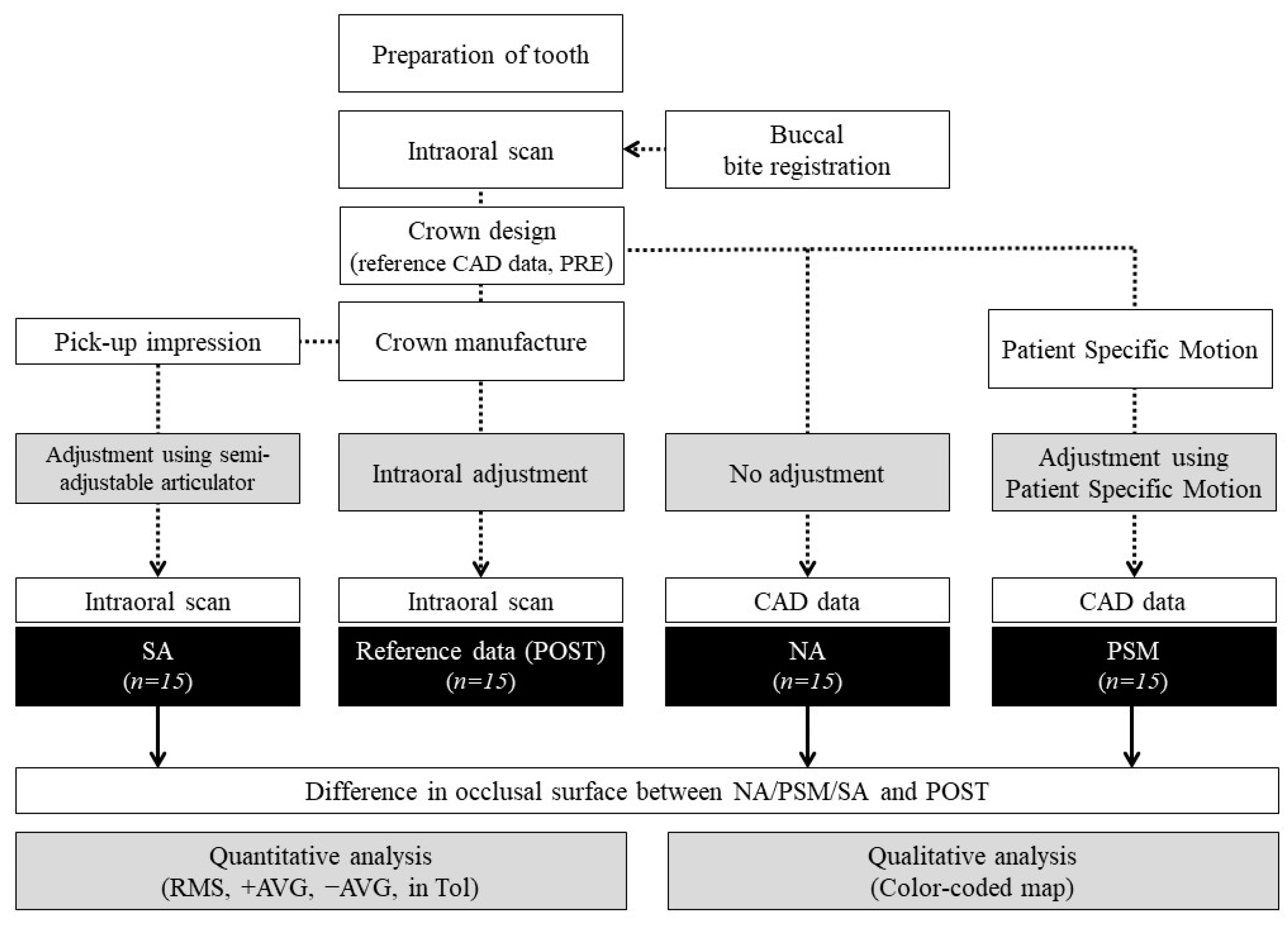
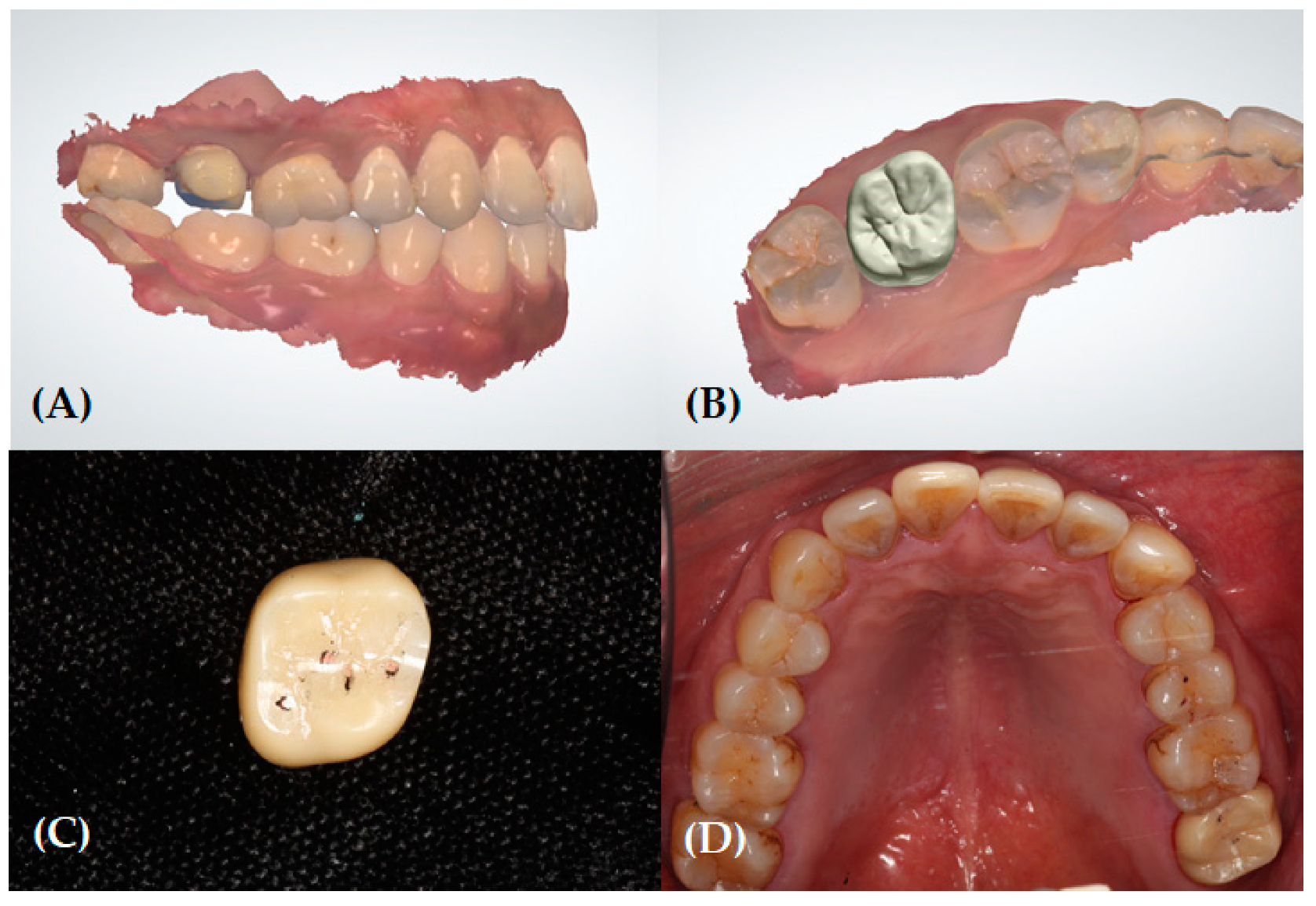
2.2. Clinical and Laboratory Procedures for Reference Data (Pre- and Post-Treatment)

The overall study workflow is presented in Figure 1. All participants had indications of a single posterior crown restoration supported by the tooth or implant. All clinical procedures were performed by a professional dentist (Y.-C.L.) with a prosthodontics specialty.
For a tooth-supported single crown, after a preliminary clinical examination, the posterior tooth preparation was made. The ideal dimensions for an occlusal reduction and an axial reduction were tried. The subgingival margin of the preparation was avoided. After preparation, the quadrant scan image of the maxilla and mandible was obtained using an IOS (Trios 3; 3Shape A/S, Copenhagen, Denmark) according to the manufacturer’s instructions (Figure 2A). The static interocclusal registration was recorded using the buccal bite registration method. For an implant-supported single crown, the acceptable osseointegration was verified before the digital impression. To acquire a digital impression, an emergence profile scan, a scan of the scan body (H-Scan body; Dio Implant Co., Busan, Korea), and an antagonist scan were performed. The interocclusal registration was recorded in the same manner as that for the tooth-supported restoration. A customized implant abutment was designed according to the principles outlined for ideal teeth.
All laboratory procedures, including the crown design and fabrication, were performed by an experienced professional dental laboratory technician (D.H.K.). Intraoral scanning data were loaded in CAD software (3Shape Dental System; 3Shape A/S, Copenhagen, Denmark). A virtual design procedure was performed using the recommended flow in CAD software. The crown contour and occlusal morphology were adjusted to achieve anatomic harmony with the adjacent and occluding teeth. Anatomic properties, such as the occlusal fit, occlusal cusp, central groove, marginal ridge, and proximal contact, were adjusted. By setting the parameters in the contacts and smoothening tab, the occlusal contact was refined. Using single-tooth tools, such as the wax knife tool, occlusal contacts were additionally adjusted and controlled by referring to the antagonist and distance map in the static occlusion state. The finished occlusal design data were considered as the reference CAD data (PRE) (Figure 2B). Finally, a zirconia crown was fabricated using a five-axis milling machine, and post-processing, such as sintering of the crown, was performed.
During the crown delivery, all crown restorations showed clinically acceptable margin adaptations when checked using a dental explorer tip. Interproximal contact was verified via double-checking. First, the interproximal contact was assessed with dental floss. Second, the patient’s identical sensation with/without a crown was verified. The tight contact was adjusted using zirconia polishing burs (Eve Diacera HP 321 kit, EVE Ernst Vetter GmbH, Keltern, Germany), whereas the loose contact was repaired by adding porcelain. The occlusal contact was evaluated using two types of articulating paper (Arti-Check Articulating Paper 40 μm, Dr. Jean Bausch Gmbh & Co. KG, Koln, Germany; Hanel Shimstock foil (8 μm), Coltene, OH, USA) [29]. Any occlusal interferences in the static and dynamic occlusion were eliminated (Figure 2C). To avoid overcorrection, posterior disocclusion was achieved by referring to the standard amount of disocclusion by Hobo [30]. After the occlusal adjustment was completed, the clinician evaluated the occlusion and confirmed that there was no patient discomfort. The adjusted crown was temporarily cemented (Temp-bond; Kerr Dental, CA, USA). One month after the temporary cementation, participants visited for final cementation. Any necessary additional occlusal adjustments were performed. Finally, the quadrant scan data of the treated area was obtained using the IOS. After intraoral scanning, the final cementation was performed (Figure 2D). The intraoral scan dataset was exported as a standard tessellation language (STL) file. This dataset was considered the reference data (POST) that had the completed anatomic and functional occlusal adjustment.

2.3. Data Acquisition for the Experimental Groups

2.3.1. No Adjustment Group (Control)

The no adjustment (NA) group were subject to conventional CAD workflow for occlusal design on static occlusion. Therefore, the STL files of the reference CAD data (PRE) were associated with the NA group.

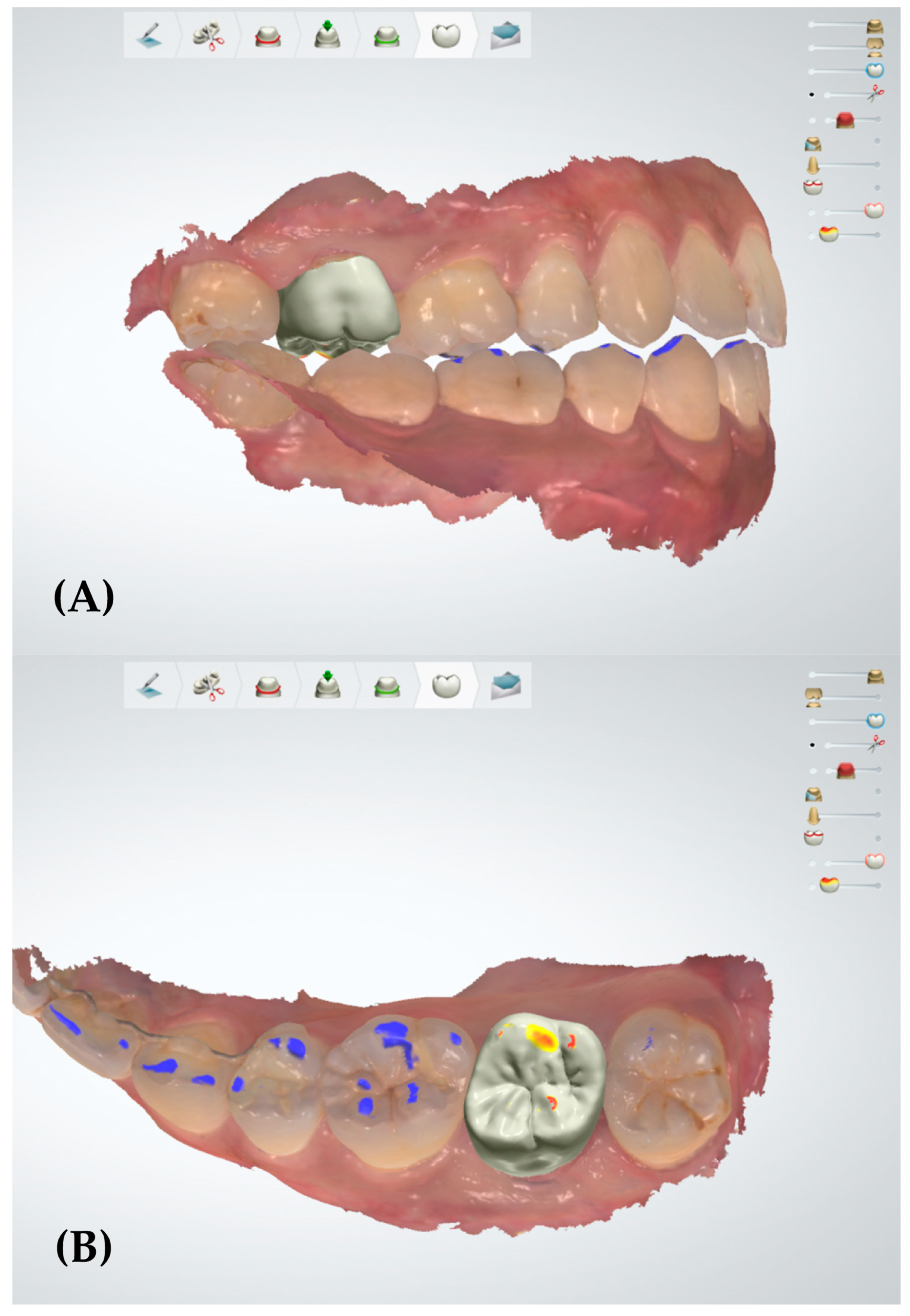
2.3.2. Patient Specific Motion Group

In the Patient Specific Motion (PSM) group, the occlusal adjustment was performed using dynamic occlusion records. For this group, a dynamic occlusion was scanned and recorded in the PSM scan step during the digital impression procedure. The reference CAD data (PRE) was duplicated and then loaded into the CAD software. The PSM function in the smart tools was executed and the running recorded articulation mode was used (Figure 3). The adapt designs button was clicked to remove occlusal interferences marked with red and yellow colors. In this way, the only additional adjustment to the reference CAD data (PRE) was made by the PSM function of the CAD software. The STL files of the altered design were associated with the PSM group.

2.3.3. Semi-Adjustable Articulator Group

The semi-adjustable articulator group (SA) group was associated with the conventional methods in which the crown restoration was adjusted by a mechanical articulator. The second zirconia crown was fabricated based on the duplicated reference CAD data (PRE). In the crown delivery procedure, only the adequate margin adaptation and interproximal contact were verified. Full-arch pick-up impressions were taken with additional silicone impression material (Aquasil Ultra; Dentsply De Trey, Konstanz, Germany) without occlusal adjustment. To place the cast derived from the pick-up impression on the articulator, the cranio-maxilla relationship was recorded using a facebow (Hanau Springbow; Whip Mix, Louisville, KY, USA) and transferred to a semi-adjustable articulator (Hanau modular 190; Whip Mix, Louisville, KY, USA). The maxilla-mandibular relationship was adjusted using an interocclusal record (Blu-Mousse; Parkell, NY, USA). The horizontal condylar angle was adjusted in the articulator using a protrusive check-bite. According to Weinberg et al. [31], Hanau’s formula can be used for the calculation of lateral condylar guidance in the Hanau modular articulator system. The lateral condylar angle value was obtained using Hanau’s formula:
L = H 8 + 12 ,
where L is the lateral condylar angle and H is the horizontal condylar angle.
After the adjustments of the articulator, the occlusal adjustment of the single crown was performed. Occlusal errors in the MICP and eccentric movement were removed using articulating paper (Arti-Check Articulating Paper 40 μm, Dr. Jean Bausch Gmbh & Co. KG; Koln, Germany; Hanel Shimstock; Coltene, OH, USA) [29,32,33]. After the occlusion adjustment was completed, the quadrant scan data were obtained using IOS. The STL files of the quadrant scan were associated with the SA group.

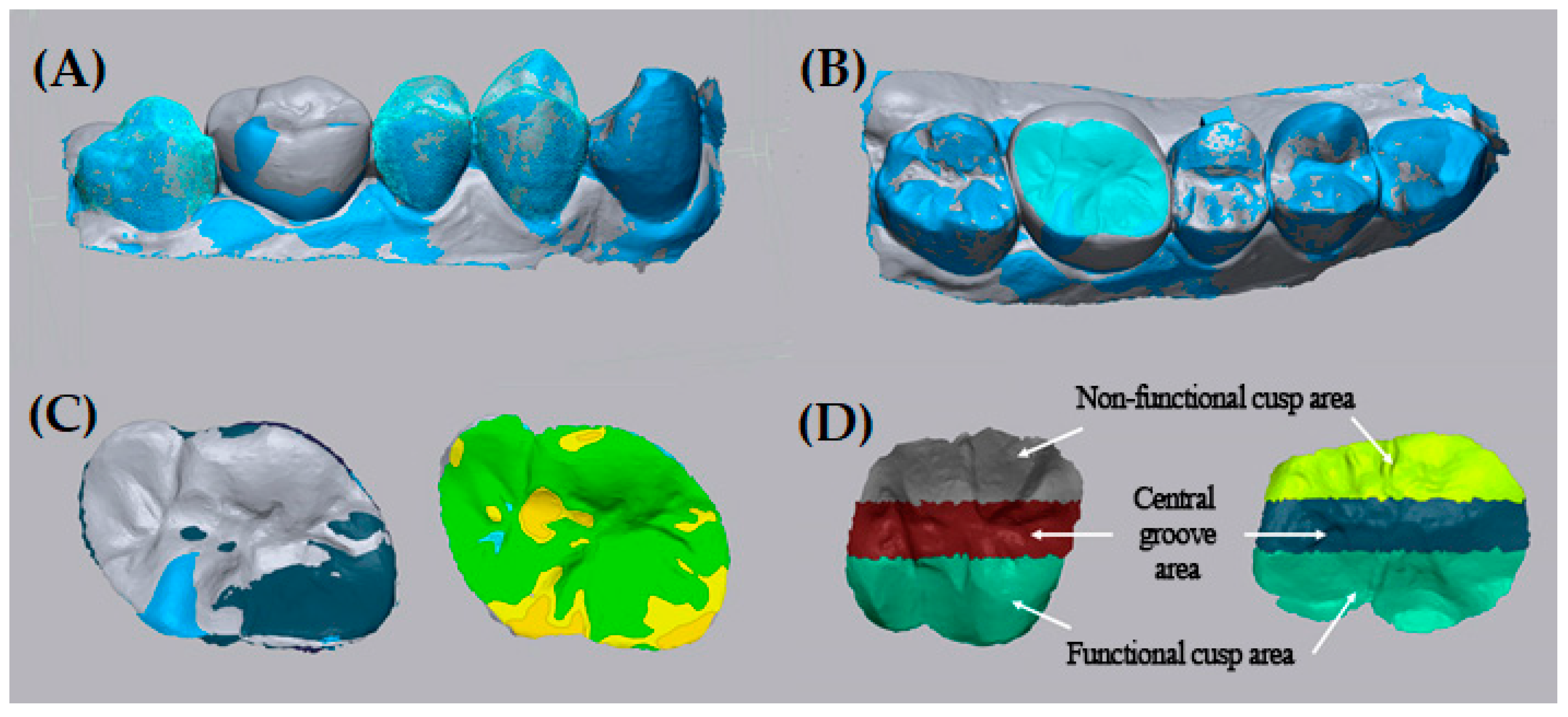
2.4. Data Processing

The NA, PSM, SA, and POST datasets were obtained from 15 participants (n = 15). All datasets in the STL files were loaded into surface analyzing software (Geomagic Control X; 3D Systems, Rock hill, SC, USA). The STL files of the three experimental groups (NA, PSM, and SA) were superimposed onto the reference data (POST) using the “align between measured data” function. The best-fit alignment was used in the arrangement. The best-fit alignment is performed using the iterative closest point (ICP) algorithm for the arrangement of mesh data [34]. The alignment of the scan data was processed via the minimization of the mesh distance error between each corresponding point. To avoid using the occlusal surface of the treated tooth for the arrangement, the field of interest was limited to the occlusal, buccal, and lingual surfaces of two premolars and one molar (Figure 4A). The tolerance level was set to 100 μm [35,36,37,38,39]. In the case of a valid alignment of the experimental model with the reference model, all areas of the teeth, except the treated tooth, were coded green. After the valid arrangement was confirmed, the field of interest for the 3D comparison was limited to the occlusal surface by trimming off the area not belonging to the occlusal surface (Figure 4B). A 3D comparison was performed to obtain the root mean square (RMS) value, the +average (AVG) deviation value, the −AVG deviation value, and the proportion inside the tolerance (TOL) value of each experimental group compared to POST. These values were used in the quantitative analysis (Figure 4C). The RMS was calculated by applying the following formula [38,40,41]:
RMS = i = 1 n ( X 1 , i X 2 , i ) 2 n ,
where n is the total number of measuring points, X 1 , i is measuring point i in the reference data, and X 2 , i is measuring point i in the comparison data of the experimental group.
The RMS can serve as a measure of how far deviations between the two different datasets vary from zero. In this study, assuming all systematic errors were removed, the only possible deviation between the reference data and the comparison data should be the sum of points in which occlusal adjustment was required. Based on this, the RMS value represents the amount of the occlusal error. To analyze the amount of occlusal error according to the functional properties of the occlusal surface, the trimmed occlusal surface was split into three subdivided areas: the functional cusp area, the non-functional cusp area, and the central groove area (Figure 4D). The reference line was determined by dividing the buccolingual dimension into three. The RMS, +AVG, −AVG, and in Tol values were calculated via a 3D comparison for each subdivided area. For the assessment of the area outside the tolerance, a dataset that included all points of deviation was exported to comma-separated values (CSV) files. After filtering out points inside the tolerance level from the dataset using spreadsheet software (Excel 2016; Microsoft Co., Redmond, WA, USA), the RMS value of the valid points were calculated.
A color-coded map of the occlusal surface was generated for the qualitative analysis (Figure 4C). The color-coded map represents the 3D deviation between the two datasets. The tolerance level in the color-coded map was 100 μm. An area coded with green represents an area inside the tolerance level, whereas an area with red or blue represents an area with a positive deviation out of the tolerance level or a negative deviation out of the tolerance level, respectively.

2.5. Statistical Analysis

Kolmogorov–Smirnov tests were performed for the RMS, +AVG deviation, −AVG deviation, and in TOL values of the NA, PSM, and SA groups. The heterogeneity of the variances between groups was measured using Levene’s test (α < 0.05). An analysis of the variance (one-way ANOVA) for the obtained values was used to assess the amount of occlusal error in single posterior crowns according to the adjustment method (NA, PSM, and SA). Tukey’s honestly significant difference (HSD) tests were performed for the post hoc analysis. A value of α = 0.05 was considered significantly different. The software SPSS 23.0 (SPSS Inc., Chicago, IL, USA) was used for all statistical analyses.

3. Results

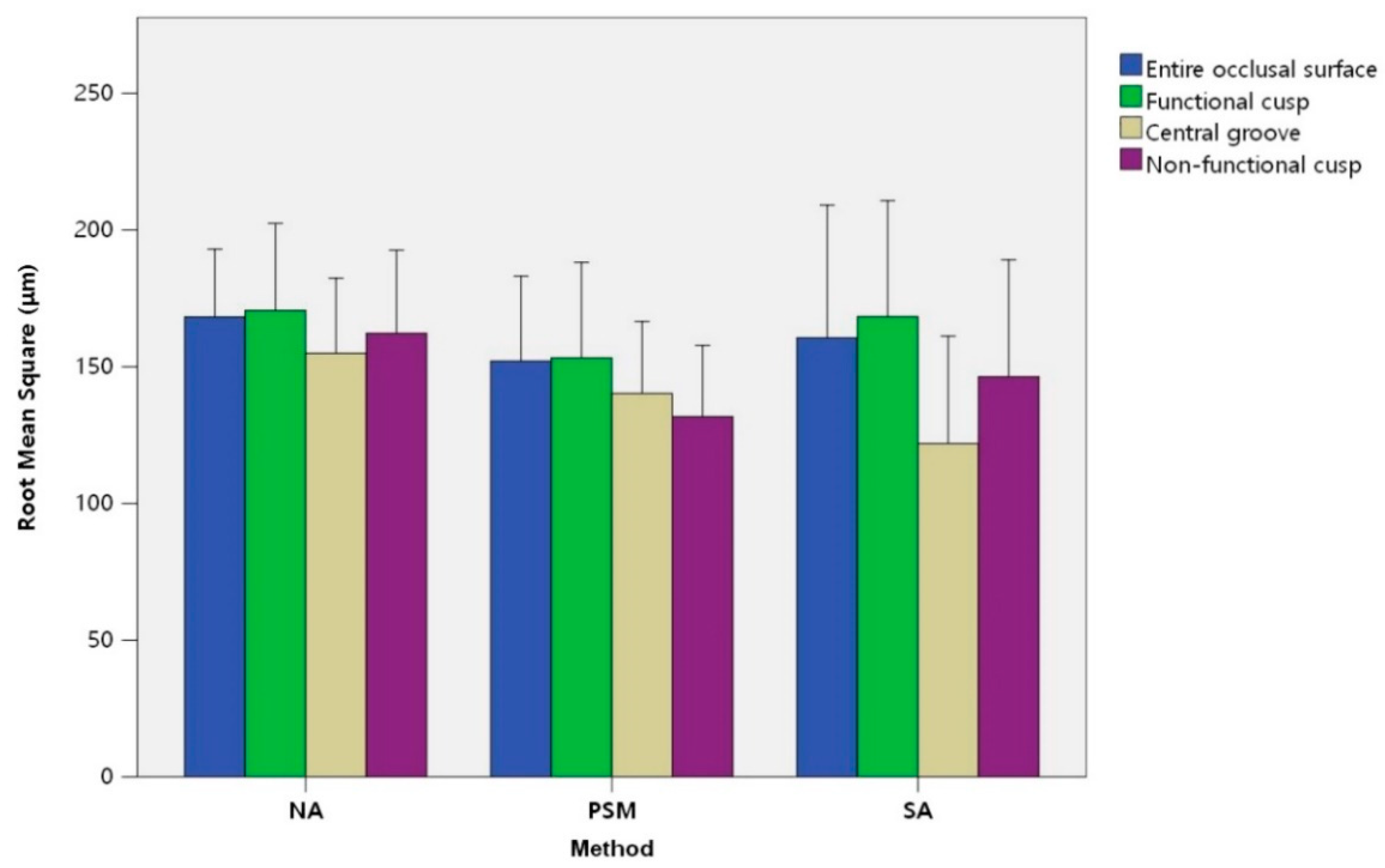
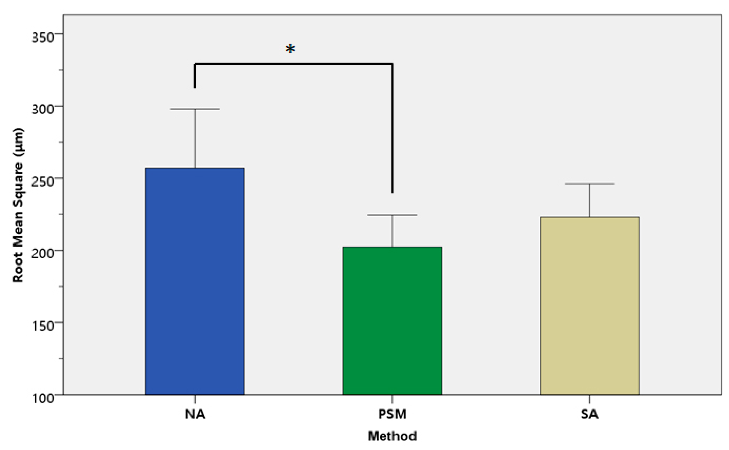
3.1. Quantitative Analysis

Table 1 shows the RMS ± standard deviation (SD) (μm), +AVG deviation ± SD (μm), −AVG deviation ± SD (μm), and in TOL (%) ± SD of the NA, PSM, and SA groups according to the occlusal surface, functional cusp area, central groove area, and non-functional cusp area, respectively. On the occlusal surface, the RMS values of the NA, PSM, and SA groups were 168.2 ± 43.3 μm, 152.1 ± 54.2 μm, and 160.6 ± 84.6 μm, respectively. The RMS value of the PSM group was lower than that of the other groups, but there was no significant difference in the one-way ANOVA (p = 0.797). The +AVG deviation values of the NA, PSM, and SA groups were 124.5 ± 45.3 μm, 112.3 ± 46.3 μm, and 135.8 ± 52.7 μm, respectively. The −AVG deviation values of the NA, PSM, and SA groups were −87.7 ± 73.1 μm, −93.1 ± 61.5 μm, and −91.5 ± 83.8 μm, respectively. The in TOL (%) values of the NA, PSM, and SA groups were 90.5 ± 6.7%, 92.9 ± 5.9%, and 91.5 ± 8.3%, respectively. The one-way ANOVA showed no statistically significant differences in the RMS value, +AVG deviation, −AVG deviation, or in TOL between the three groups (p = 0.443, 0.980, and 0.658, respectively). An analogous tendency was indicated in the split areas according to functional properties (Figure 5).
For the area outside of the tolerance level, which was regarded as occlusal errors in this study, the results are described in Table 1 and Figure 6. There were significant differences in the RMS values of the NA, PSM, and SA groups (p = 0.028). The RMS values calculated from all points outside of the tolerance area were 257.0 ± 73.9 μm in the NA group, 202.3 ± 39.3 μm in the PSM group, and 222.9 ± 41.9 μm in the SA group. From the post hoc analysis, the RMS of the PSM group was statistically lower than the NA group (Figure 6). The +AVG values were 210.9 ± 48.6 μm in the NA group, 173.1 ± 31.31 μm in the PSM group, and 194.7 ± 36.4 μm in the SA group. There was also a significant difference between the NA and PSM groups in the post hoc analysis (p = 0.040).

3.2. Qualitative Analysis

The color-coded map represents the occlusal surface deviations between the comparison data of the three experimental groups and the reference data. The representative results of the qualitative analysis are presented in Figure 7. Areas in green (i.e., within the tolerance range) were considered positions that required no clinical occlusal adjustment. The areas coded in red (i.e., positive deviation out of the tolerance range) signified occlusal errors that required clinical occlusal adjustment. The areas in blue (i.e., negative deviation out of the tolerance range) implied an over-correction in the laboratory occlusal adjustment or over-milling due to a limitation of the milling machine.
In the three groups, most of the occlusal surfaces were coded green. The red-coded areas indicating occlusal error were mainly on the cusp tip and the inclined plane of the cusp. In some cases in the NA and PSM groups, the central groove was coded blue. The PSM group showed a decreased extent of occlusal error compared to the other groups (Figure 7). The areas of occlusal error were mainly reduced in the triangular ridge, the lingual inclined plane of the buccal cusp, and the buccal inclined plane of the lingual cusp. However, in the cusp tip and central fossa, the areas of occlusal error remained. The SA group also exhibited a decrease in the red-coded area compared to the NA group. Most positions of the reduced areas were like that in the PSM group. However, in some cases, the reduced error area was different than that of the PSM group (Figure 7C). In addition, there were some cases in which an extensive negative deviation area appeared, which meant that there was an over-correction (Figure 7B). The occlusal error area of the NA group mainly showed on the cusp tip, triangular ridge, and inclined plane of the cusp.

4. Discussion

The purpose of this study was to assess the amount of occlusal error in the occlusal surface that was adjusted with the PSM compared to other methods, namely, using the traditional mechanical semi-adjustable articulator or current CAD software. The traditional method decreased the occlusal error based on the occlusal knowledge of the clinician and the skill of the technician [25]. For more accurate fabrication, the patient’s condylar and anterior guidance and cranio-maxilla-mandibular relationships were adjusted using a semi-adjustable articulator or fully adjustable articulator [13,15]. Although simulated mandibular movement could contribute to reduced occlusal errors in the oral cavity [13], it was difficult to establish a full functional occlusion. With the development of digital technology, digital workflows are being applied in many areas of dentistry [42,43]. Recently, dynamic occlusion has been used in CAD software by tracking and reproducing mandibular movement [7,19]. The PSM is one such method. Because this method uses only an IOS, it reproduces the mandibular movement simply and quickly. However, to the author’s knowledge, there is no research on whether digital workflows using the digitally reproduced dynamic occlusion are clinically superior to conventional methods.
In this study, the deviations out of the tolerance level between the reference data (POST) and the comparison data (NA, PSM, and SA) were defined as occlusal errors that require occlusal adjustment. In other words, the RMS value represents the amount of occlusal error in the experimental groups. The RMS values of the occlusal surface in the NA, PSM, and SA groups were 168.2 ± 43.3 μm, 152.1 ± 54.2 μm, and 160.6 ± 84.6 μm, respectively. In addition, the RMS values of out of the tolerance level were 257.0 ± 73.9 μm, 202.3 ± 39.8 μm, and 222.9 ± 41.9 μm, respectively. In the case of the latter, there were statistically significant differences between the three groups. As a result, our null hypothesis was partially rejected. The result of the quantitative analysis signified that the overall occlusal surface did not differ between the three groups in single restorations in posterior teeth. It also suggested that all groups had occlusal errors in the oral cavity to some extent and required clinical intraoral adjustment. However, when limited to areas out of the tolerance level denoting occlusal errors, the extent of the errors was decreased in the adjusted PSM group. The RMS value did not measure the clinical quality but only the difference between the experimental data and the reference data. In further research, measures of clinical quality, such as the adjustment time, should be evaluated for dynamic occlusion, as recorded using PSM [44].
In a qualitative analysis by Olthoff et al. [45], an occlusal morphology of a single crown using the FGP technique with the CAD/CAM (Computer-aided manufacturing) system was compared to a crown with static occlusion. The difference was mainly on the distobuccal portion of the occlusal surface. However, no statistical analysis was performed in this study. Lin et al. [46] reported that a single crown designed by the FGP technique showed more significant changes in the occlusion and disocclusion times than those from conventional single crowns. The occlusion and disocclusion times were measured using a computerized occlusal analysis system (T-scan). The result indicated an easier occlusal adjustment in the FGP single crown, although the clinically relevant differences were small. In another study, Saini et al. [47] studied an occlusal surface that was designed using a virtual mastication simulator. Comparing the obtained results with an actual tooth, these subject-specific functional occlusal surfaces displayed errors in functional and static occlusion, which ranged between 90 and 200 μm. The result of that study is in agreement with our study.
In the color-coded map analysis, occlusal interference mainly occurred in the lingual inclined plane of the buccal cusp and in the buccal inclined plane of the lingual cusp. If this occlusal interference was not eliminated in the clinical occlusal adjustment procedure, various signs, such as local tooth pain, loosening of the tooth, excessive wear, and a change in chewing stroke patterns, can appear [7,48,49,50]. In addition, it is problematic to directly identify occlusal errors in the patient’s mouth due to factors such as the presence of saliva, visualization limitations, and an incomplete marking ability of the articulating paper [51,52]. In this aspect, any possible occlusal errors are minimized in the occlusal design procedure. Considering the significant differences of the RMS in the out of tolerance area between groups, an adjustment using dynamic occlusion might be helpful to eliminate the errors in advance. In both the PSM and SA groups, the area of the occlusal error decreased in the color-coded map. However, in the SA group, there were cases in which excessive occlusal adjustment occurred. If the ipsilateral laterotrusion or incisal guide angle is not adjusted correctly in the articulator, over-correction may result [6]. Most semi-adjustable articulators have straight rather than convex condylar pathways [53]. This feature, called the “safety factor,” could contribute to an excessive occlusal adjustment [54]. Because the mechanical articulator does not directly reconstruct mandibular movement, there is a limitation in eliminating occlusal interference during eccentric movement [14]. In the NA group, the occlusal error occurred because the occlusal surface was designed using only static occlusion. The skill and experience of the technician are still the main concerns when designing occlusal morphology on current CAD software [7]. The complete elimination of occlusal error was not easy due to the lack of mandibular movement information.
In the PSM group, not all occlusal errors could be reduced because of inaccuracies caused by various factors. Some studies have reported that the accuracy of a mandibular motion tracking system is 0.2–0.3 mm [7,47]. In addition, movement in loaded teeth and adjacent teeth cannot be recorded with an optical tracking device [21]. The muscle forces exerted during functional movement may cause the mandible and the teeth to deform, which is not recorded when tracking mandibular motion [55]. These limitations may contribute to the remaining occlusal error. In addition, limitations of the intraoral scanner, such as tip size, scanning speed, and sample frequency, affect the accuracy of the mandibular motion tracking record [56,57]. The dynamic mandibular movement is recorded on the buccal side of the teeth without a marker in the PSM. As with other markerless tracking systems, excessive movement over the sampling frequency in opening or horizontal movement causes a defective frame in the records called the “judder effect” [57]. However, the PSM method is meaningful as a simple alternative tool [7]. Conventional mandibular motion tracking based on optical tracking devices has some disadvantages, such as increased cost, the time required for preparing devices, and the existence of a learning curve [7]. In addition, the existence of the marker makes clinical procedures time-consuming and more technique-sensitive [58]. The marker attached to the teeth might interfere with the movement of the mandible [57]. However, like the buccal bite registration, the PSM method makes it possible to record eccentric movements in the buccal surface of the posterior tooth using only an IOS.
In our study, qualitative and quantitative analyses were performed by evaluating three-dimensional discrepancies between two aligned surfaces. Occlusal surface scan data was obtained using an intraoral scanner, which is currently known to be valid for the measurement of single teeth or quadrants [59,60]. The commercial software used for our study, Geomagic control X, processes the best-fit alignment based on the ICP algorithm. A standard best-fit alignment minimizes the mesh distance errors for all vertices of a dataset [34]. However, if there is a large defect or difference (i.e., on the occlusal surface of a treated tooth in the case of our study) between the datasets, this can cause an erroneous result during the metrological alignment process [34]. To avoid this, a reference best-fit alignment has been proposed in recent research [61]. In a reference best-fit alignment, the alignment process of the dataset is restricted to operator-identified areas of the dataset, where the least change is expected [62]. In our study, the occlusal surface of the treated tooth was excluded from the field of interest for an arrangement based on a reference best-fit alignment. Furthermore, a recent study suggested that volumetric analysis based on custom ICP algorithms has high analysis reliability in addition to linear analysis using commercial software [63].
When calculating the deviation from the reference data, the accuracy of the IOS and control of the milling process and sintering shrinkage can influence the accuracy of the deviation. The tolerance range of 100 μm was determined in consideration of these factors [35,36,37,38,39]. In previous studies, the precision of the quadrant scan using Trios was about 50 μm [37,38,39]. The accuracy of the manufacturing and post-processing of a milled single zirconia crown was about 50 μm [35,36]. Because the STL files from CAD were used in the PSM and NA groups, negative deviation occurred in the occlusal groove, but the effect of this systematic error might have been minimized in the rest of the area. However, the relatively broad range of tolerance levels was a limitation of this study, in addition to the heterogeneity of the occlusal surface data between groups.
This study was limited to the comparison of occlusal error in a single posterior crown restoration. Future clinical research should investigate the positive outcome of PSM using different positions and spans of restoration, such as single anterior restoration or a long-span fixed partial denture. In addition, a randomized controlled clinical trial is further required to reduce the dataset heterogeneity between the experimental groups and to enhance the evidence level.

5. Conclusions

Within the limitations of this clinical study, the following conclusions were drawn:
  • In the quantitative analysis, there was a statistically reduced occlusal error in the group with adjustments using PSM on the out of tolerance area compared to the group design based on static occlusion. However, no significant difference in the amount of occlusal error was revealed in the entire and subdivided occlusal surface level between the PSM and conventional methods.
  • In the qualitative analysis, a decrease of the occlusal error areas was mainly displayed in the inclined plane of the cusp and triangular ridge on the occlusal surface in a single posterior crown adjusted with the PSM.
  • The PSM may be a simple and effective alternative tool that shows clinically acceptable results in the occlusal adjustment of a single posterior crown.

Author Contributions

Conceptualization, Y.-C.L. and K.-W.L.; methodology, J.-E.K.; software, Y.-C.L. and C.L.; validation, Y.-C.L., J.-M.P., and Y.S.; formal analysis, J.-E.K.; investigation, Y.-C.L.; resources, J.-S.S.; data curation, Y.S.; writing—original draft preparation, Y.-C.L. and J.-E.K.; writing—review and editing, Y.-C.L. and K.-W.L.; visualization, Y.-C.L. and C.L.; supervision, K.-W.L.; project administration, K.-W.L. and J.-S.S. All authors have read and agreed to the published version of the manuscript.

Funding

This research was supported by Basic Science Research Program through the National Research Foundation of Korea(NRF) funded by the Ministry of Education (NRF- 2019R1I1A1A01062792).

Acknowledgments

The authors thank Dae Hwan Kim, the dental technician from the Department of Prosthodontics Yonsei University Wonju College of Medicine for his support regarding the laboratory work.

Conflicts of Interest

The authors declare no conflict of interest.

References

  1. Thompson, J.R. Concepts regarding function of the stomatognathic system. J. Am. Dent. Assoc. 1954, 48, 626–637. [Google Scholar] [CrossRef] [PubMed]
  2. Christensen, G.J. Is occlusion becoming more confusing? A plea for simplicity. J. Am. Dent. Assoc. 2004, 135, 767–768. [Google Scholar] [CrossRef] [PubMed]
  3. Turp, J.C.; Greene, C.S.; Strub, J.R. Dental occlusion: A critical reflection on past, present and future concepts. J. Oral Rehabil. 2008, 35, 446–453. [Google Scholar] [CrossRef] [PubMed]
  4. Parmar, A.; Choukse, V.; Palekar, U.; Srivastava, R. An Appraisal on Occlusal Philosophies in Full-mouth Rehabilitation: A Literature Review. Eur. J. Prosthodont. 2016, 6, 89–92. [Google Scholar]
  5. Fiore, A.D.; Monaco, C.; Brunello, G.; Granata, S.; Stellini, E.; Yilmaz, B. Automatic Digital Design of the Occlusal Anatomy of Monolithic Zirconia Crowns Compared to Dental Technicians’ Digital Waxing: A Controlled Clinical Trial. J. Prosthodont. 2020. [Google Scholar] [CrossRef]
  6. Olthoff, L.; Meijer, I.; de Ruiter, W.; Bosman, F.; van der Zel, J. Effect of virtual articulator settings on occlusal morphology of CAD/CAM restorations. Int. J. Comput. Dent. 2007, 10, 171–185. [Google Scholar]
  7. Fang, J.-J.; Kuo, T.-H. Tracked motion-based dental occlusion surface estimation for crown restoration. Comput. Aided Des. 2009, 41, 315–323. [Google Scholar] [CrossRef]
  8. Gracis, S. Clinical considerations and rationale for the use of simplified instrumentation in occlusal rehabilitation. Part 1: Mounting of the models on the articulator. Int. J. Periodontics Restor. Dent. 2003, 23, 57–67. [Google Scholar]
  9. Pröschel, P.; Morneburg, T.; Hugger, A.; Kordass, B.; Ottl, P.; Niedermeier, W.; Wichmann, M. Articulator-related registration—A simple concept for minimizing eccentric occlusal errors in the articulator. Int. J. Prosthodont. 2002, 15, 289–294. [Google Scholar]
  10. Schulte, J.K.; Wang, S.H.; Erdman, A.G.; Anderson, G.C. Three-dimensional analysis of cusp travel during a nonworking mandibular movement. J. Prosthet. Dent. 1985, 53, 839–843. [Google Scholar] [CrossRef]
  11. Schulte, J.K.; Wang, S.H.; Erdman, A.G.; Anderson, G.C. Working condylar movement and its effects on posterior occlusal morphology. J. Prosthet. Dent. 1985, 54, 118–121. [Google Scholar] [CrossRef]
  12. Weinberg, L.A. An evaluation of basic articulators and their concepts: Part I. Basic concepts. J. Prosthet. Dent. 1963, 13, 622–644. [Google Scholar] [CrossRef]
  13. Hobo, S.; Shillingburg, H.T.; Whitsett, L.D. Articulator selection for restorative dentistry. J. Prosthet. Dent. 1976, 36, 35–43. [Google Scholar] [CrossRef]
  14. Kim, J.-E.; Park, J.-H.; Moon, H.-S.; Shim, J.-S. Complete assessment of occlusal dynamics and establishment of a digital workflow by using target tracking with a three-dimensional facial scanner. J. Prosthodont. Res. 2019, 63, 120–124. [Google Scholar] [CrossRef] [PubMed]
  15. Ak, V.; Ali, M.; Chaturvedi, S.; Naeem, A.; Amrit, R. Articulators—A review article. Int. J. Appl. Res. 2014, 1, 6–8. [Google Scholar]
  16. Meyer, F.S. The generated path technique in reconstruction dentistry: Part II. Fixed partial dentures. J. Prosthet. Dent. 1959, 9, 432–440. [Google Scholar] [CrossRef]
  17. Pankey, L.D.; Mann, A.W. Oral rehabilitation: Part II. Reconstruction of the upper teeth using a functionally generated path technique. J. Prosthet. Dent. 1960, 10, 151–162. [Google Scholar] [CrossRef]
  18. Curtis, S.R. Functionally generated paths for ceramometal restorations. J. Prosthet. Dent. 1999, 81, 33–36. [Google Scholar] [CrossRef]
  19. Mehl, A. A new concept for the integration of dynamic occlusion in the digital construction process. Int. J. Comput. Dent. 2012, 15, 109–123. [Google Scholar]
  20. Di Fiore, A.; Meneghello, R.; Graiff, L.; Savio, G.; Vigolo, P.; Monaco, C.; Stellini, E. Full arch digital scanning systems performances for implant-supported fixed dental prostheses: A comparative study of 8 intraoral scanners. J. Prosthodont. Res. 2019, 63, 396–403. [Google Scholar] [CrossRef]
  21. Bando, E.; Nishigawa, K.; Nakano, M.; Takeuchi, H.; Shigemoto, S.; Okura, K.; Satsuma, T.; Yamamoto, T. Current status of researches on jaw movement and occlusion for clinical application. Jpn. Dent. Sci. Rev. 2009, 45, 83–97. [Google Scholar] [CrossRef] [Green Version]
  22. Ender, A.; Mörmann, W.H.; Mehl, A. Efficiency of a mathematical model in generating CAD/CAM-partial crowns with natural tooth morphology. Clin. Oral Investig. 2011, 15, 283–289. [Google Scholar] [CrossRef] [PubMed] [Green Version]
  23. Baroudi, K.; Ibraheem, S.N. Assessment of Chair-side Computer-Aided Design and Computer-Aided Manufacturing Restorations: A Review of the Literature. J. Int. Oral Health 2015, 7, 96–104. [Google Scholar] [PubMed]
  24. Ender, A.; Zimmermann, M.; Attin, T.; Mehl, A. In vivo precision of conventional and digital methods for obtaining quadrant dental impressions. Clin. Oral Investig. 2016, 20, 1495–1504. [Google Scholar] [CrossRef] [PubMed] [Green Version]
  25. Sornsuwan, T.; Swain, M.V. Influence of occlusal geometry on ceramic crown fracture; role of cusp angle and fissure radius. J. Mech. Behav. Biomed. 2011, 4, 1057–1066. [Google Scholar] [CrossRef]
  26. Valenti, M.; Schmitz, J.H. A reverse digital workflow by using an interim restoration scan and patient-specific motion with an intraoral scanner. J. Prosthet. Dent. 2020, in press. [Google Scholar] [CrossRef]
  27. Faul, F.; Erdfelder, E.; Buchner, A.; Lang, A.-G. Statistical power analyses using G*Power 3.1: Tests for correlation and regression analyses. Behav. Res. Methods 2009, 41, 1149–1160. [Google Scholar] [CrossRef] [Green Version]
  28. Kollmuss, M.; Jakob, F.-M.; Kirchner, H.-G.; Ilie, N.; Hickel, R.; Huth, K.C. Comparison of biogenerically reconstructed and waxed-up complete occlusal surfaces with respect to the original tooth morphology. Clin. Oral Investig. 2013, 17, 851–857. [Google Scholar] [CrossRef]
  29. Brizuela-Velasco, A.; Álvarez-Arenal, Á.; Ellakuria-Echevarria, J.; del Río-Highsmith, J.; Santamaría-Arrieta, G.; Martín-Blanco, N. Influence of Articulating Paper Thickness on Occlusal Contacts Registration: A Preliminary Report. Int. J. Prosthodont. 2015, 28, 360–362. [Google Scholar] [CrossRef] [Green Version]
  30. Hobo, S.; Takayama, H. Twin-stage procedure. Part 1: A new method to reproduce precise eccentric occlusal relations. Int. J. Periodontics Restor. Dent. 1997, 17, 112–123. [Google Scholar]
  31. Weinberg, L.A. An evaluation of basic articulators and their concepts: Part II. Arbitrary, positional, semi adjustable articulators. J. Prosthet. Dent. 1963, 13, 645–663. [Google Scholar] [CrossRef]
  32. Boyarsky, H.P.; Loos, L.G.; Leknius, C. Occlusal refinement of mounted casts before crown fabrication to decrease clinical time required to adjust occlusion. J. Prosthet. Dent. 1999, 82, 591–594. [Google Scholar] [CrossRef]
  33. Meng, J.C.; Nagy, W.W.; Wirth, C.G.; Buschang, P.H. The effect of equilibrating mounted dental stone casts on the occlusal harmony of cast metal complete crowns. J. Prosthet. Dent. 2010, 104, 122–132. [Google Scholar] [CrossRef]
  34. O’Toole, S.; Osnes, C.; Bartlett, D.; Keeling, A. Investigation into the accuracy and measurement methods of sequential 3D dental scan alignment. Dent. Mater. 2019, 35, 495–500. [Google Scholar] [CrossRef] [PubMed]
  35. Al Hamad, K.Q.; Al-Rashdan, R.B.; Al-Rashdan, B.A.; Baba, N.Z. Effect of Milling Protocols on Trueness and Precision of Ceramic Crowns. J. Prosthodont. 2020. [Google Scholar] [CrossRef] [PubMed]
  36. Bosch, G.; Ender, A.; Mehl, A. A 3-dimensional accuracy analysis of chairside CAD/CAM milling processes. J. Prosthet. Dent. 2014, 112, 1425–1431. [Google Scholar] [CrossRef] [Green Version]
  37. Mangano, F.G.; Hauschild, U.; Veronesi, G.; Imburgia, M.; Mangano, C.; Admakin, O. Trueness and precision of 5 intraoral scanners in the impressions of single and multiple implants: A comparative in vitro study. BMC Oral Health 2019, 19, 101. [Google Scholar] [CrossRef] [Green Version]
  38. Wang, W.; Yu, H.; Liu, Y.; Jiang, X.; Gao, B. Trueness analysis of zirconia crowns fabricated with 3-dimensional printing. J. Prosthet. Dent. 2019, 121, 285–291. [Google Scholar] [CrossRef]
  39. Yang, X.; Lv, P.; Liu, Y.; Si, W.; Feng, H. Accuracy of Digital Impressions and Fitness of Single Crowns Based on Digital Impressions. Materials 2015, 8, 3945–3957. [Google Scholar] [CrossRef]
  40. Schaefer, O.; Watts, D.C.; Sigusch, B.W.; Kuepper, H.; Guentsch, A. Marginal and internal fit of pressed lithium disilicate partial crowns in vitro: A three-dimensional analysis of accuracy and reproducibility. Dent. Mater. 2012, 28, 320–326. [Google Scholar] [CrossRef]
  41. Kim, C.-M.; Kim, S.-R.; Kim, J.-H.; Kim, H.-Y.; Kim, W.-C. Trueness of milled prostheses according to number of ball-end mill burs. J. Prosthet. Dent. 2016, 115, 624–629. [Google Scholar] [CrossRef] [PubMed]
  42. Beuer, F.; Schweiger, J.; Edelhoff, D. Digital dentistry: An overview of recent developments for CAD/CAM generated restorations. Br. Dent. J. 2008, 204, 505–511. [Google Scholar] [CrossRef] [PubMed]
  43. Strub, J.R.; Rekow, E.D.; Witkowski, S. Computer-aided design and fabrication of dental restorations: Current systems and future possibilities. J. Am. Dent. 2006, 137, 1289–1296. [Google Scholar] [CrossRef] [PubMed]
  44. Wang, F.; Tang, Q.; Xi, S.; Liu, R.; Niu, L. Comparison and evaluation of the morphology of crowns generated by biogeneric design technique with CEREC chairside system. PLoS ONE 2020, 15, e0227050. [Google Scholar] [CrossRef] [PubMed] [Green Version]
  45. Olthoff, L.W.; van der Zel, J.M.; de Ruiter, W.J.; Vlaar, S.T.; Bosman, F. Computer modeling of occlusal surfaces of posterior teeth with the CICERO CAD/CAM system. J. Prosthet. Dent. 2000, 84, 154–162. [Google Scholar] [CrossRef]
  46. Lin, P.-t.; Jiao, Y.; Zhao, S.-j.; Wang, F.; Li, L.; Yu, F.; Tian, M.; Yu, H.-h.; Chen, J.-h. Occlusion and Disocclusion Time Changes in Single Unit Crowns Designed by Functional Generated Path Technique: A Randomised Clinical Trial. Sci. Rep. 2017, 7, 388. [Google Scholar] [CrossRef] [Green Version]
  47. Saini, H.; Wadell, J.N.; Pullan, A.J.; Röhrle, O. Automatically Generating Subject-specific Functional Tooth Surfaces Using Virtual Mastication. Biomed. Eng. 2009, 37, 1646–1653. [Google Scholar] [CrossRef]
  48. Clark, G.T.; Tsukiyama, Y.; Baba, K.; Watanabe, T. Sixty-eight years of experimental occlusal interference studies: What have we learned? J. Prosthet. Dent. 1999, 82, 704–713. [Google Scholar] [CrossRef]
  49. Dawson, P.E. Determining the determinants of occlusion. Int. J. Periodont. Rest. 1983, 3, 8–21. [Google Scholar]
  50. Watamoto, T.; Egusa, H.; Mizumori, T.; Yashiro, K.; Takada, K.; Yatani, H. Restoration of occlusal and proximal contacts by a single molar crown improves the smoothness of the masticatory movement. J. Dent. 2008, 36, 984–992. [Google Scholar] [CrossRef]
  51. Davies, S.J.; Gray, R.M.J.; Smith, P.W. Good occlusal practice in simple restorative dentistry. Br. Dent. J. 2001, 191, 365–381. [Google Scholar] [CrossRef] [PubMed]
  52. Altarakemah, Y.; Akbar, J.; Akthar, S.; Qudeimat, M.A.; Omar, R. Evaluation of a Technique for Reducing Chairside Occlusal Adjustment of Crowns. J. Prosthodont. 2020. [Google Scholar] [CrossRef] [PubMed]
  53. Gracis, S. Clinical considerations and rationale for the use of simplified instrumentation in occlusal rehabilitation. Part 2: Setting of the articulator and occlusal optimization. Int. J. Periodont. Rest. 2003, 23, 139–145. [Google Scholar]
  54. Dawson, P.E. Functional Occlusion-e-Book: From TMJ to Smile Design; Elsevier Health Sciences: Amsterdam, The Netherlands, 2006. [Google Scholar]
  55. van Essen, N.L.; Anderson, I.A.; Hunter, P.J.; Carman, J.; Clarke, R.D.; Pullan, A.J. Anatomically based modelling of the human skull and jaw. Cells Tissues Organs 2005, 180, 44–53. [Google Scholar] [CrossRef] [PubMed]
  56. Mangano, F.; Gandolfi, A.; Luongo, G.; Logozzo, S. Intraoral scanners in dentistry: A review of the current literature. BMC Oral Health 2017, 17, 149. [Google Scholar] [CrossRef] [PubMed] [Green Version]
  57. Tanaka, Y.; Yamada, T.; Maeda, Y.; Ikebe, K. Markerless three-dimensional tracking of masticatory movement. J. Biomech. 2016, 49, 442–449. [Google Scholar] [CrossRef]
  58. Zoss, G.; Beeler, T.; Gross, M.; Bradley, D. Accurate markerless jaw tracking for facial performance capture. Acm Trans. Graph. 2019, 38, 1–8. [Google Scholar] [CrossRef]
  59. Lancellotta, V.; Pagano, S.; Tagliaferri, L.; Piergentini, M.; Ricci, A.; Montecchiani, S.; Saldi, S.; Chierchini, S.; Cianetti, S.; Valentini, V.; et al. Individual 3-dimensional printed mold for treating hard palate carcinoma with brachytherapy: A clinical report. J. Prosthet. Dent. 2019, 121, 690–693. [Google Scholar] [CrossRef]
  60. Nedelcu, R.; Olsson, P.; Nyström, I.; Thor, A. Finish line distinctness and accuracy in 7 intraoral scanners versus conventional impression: An in vitro descriptive comparison. BMC Oral Health 2018, 18, 27. [Google Scholar] [CrossRef]
  61. Wulfman, C.; Koenig, V.; Mainjot, A.K. Wear measurement of dental tissues and materials in clinical studies: A systematic review. Dent. Mater 2018, 34, 825–850. [Google Scholar] [CrossRef]
  62. Stober, T.; Bermejo, J.L.; Rammelsberg, P.; Schmitter, M. Enamel wear caused by monolithic zirconia crowns after 6 months of clinical use. J. Oral. Rehabil. 2014, 41, 314–322. [Google Scholar] [CrossRef] [PubMed]
  63. Pagano, S.; Moretti, M.; Marsili, R.; Ricci, A.; Barraco, G.; Cianetti, S. Evaluation of the Accuracy of Four Digital Methods by Linear and Volumetric Analysis of Dental Impressions. Materials 2019, 12, 1958. [Google Scholar] [CrossRef] [PubMed] [Green Version]
Figure 1. Workflow that was used to compare the amount of occlusal error between the experimental groups. CAD, computer-aided design; NA, no adjustment group; PSM, Patient Specific Motion group; SA, semi-adjustable articulator group; RMS, root mean square; AVG, average; in Tol, inside the tolerance level.
Applsci 10 09140 g001
Figure 2. Clinical procedure for the reference data (PRE and POST). (A) Quadrant intraoral scan data of a prepared tooth obtained using the IOS (Trios 3). (B) Design of the occlusal morphology of a single posterior crown. The crown was designed based on a static occlusal relationship using CAD software (3shape Dental System). The finished CAD design was considered to be the reference CAD data (PRE). (C) Occlusal surface of a zirconia crown for which a clinical occlusal adjustment was completed under static and dynamic occlusion. (D) Intraoral photo of a single crown restoration after the adjustment. The quadrant intraoral scan data of the treated area was considered to be reference data (POST).
Applsci 10 09140 g002
Figure 3. Adjustment with Patient Specific Motion for the PSM group. (A) In the running recorded articulation mode, the recorded dynamic occlusion was visually reproduced in the CAD software. (B) After running the recorded articulation, the red and yellow colors were marked in the crown design, and the marked areas were removed in the CAD software.
Applsci 10 09140 g003
Figure 4. Data processing of the experimental groups. (A) The field of interest for the superimposition was limited to two premolars and one molar, except for the treated tooth. (B) Selection of the occlusal surface. The area not belonging to the occlusal surface was removed. (C) 3D comparison using surface analyzing software. For the entire occlusal surface and outside of the tolerance area, the representative values of the occlusal error were calculated. A color-coded map was generated for comparison. (D) To analyze the amount of occlusal error according to the functional properties of the occlusal surface, the occlusal surface was split into three areas. The representative values of occlusal error from each subdivided area were calculated.
Applsci 10 09140 g004
Figure 5. The RMS values of the three experimental groups (NA, PSM, and SA). The RMS value represents the amount of occlusal error compared to the reference data (POST). The mean of the RMS of the PSM group was lower than those in the other groups. However, there was no significant difference in the one-way ANOVA between the three groups. NA, the group with no adjustment; PSM, the group adjusted using Patient Specific Motion; SA, the group adjusted with a semi-adjustable articulator; RMS, root mean square.
Applsci 10 09140 g005
Figure 6. The RMS values outside of the tolerance area. Asterisks (*) indicate significant differences in the RMS values between groups in the post hoc analysis. NA, the group with no adjustment; PSM, the group adjusted using Patient Specific Motion; SA, the group adjusted with a semi-adjustable articulator; RMS, root mean square.
Applsci 10 09140 g006
Figure 7. Representative images of the color-coded maps showing the deviations between the comparison data (NA, PSM, and SA) and the reference data (POST). The red-coded areas (i.e., positive deviation out of the tolerance range) suggested occlusal error that required clinical occlusal adjustment. (A) The PSM and SA groups showed less red-coded areas than the NA group. (B) In some cases, there were extensively blue-coded areas in the SA group, indicating over-correction. (C) Reduced red-coded areas were observed in different positions between the PSM and SA groups.
Applsci 10 09140 g007
Table 1. Analysis of the representative values for occlusal error between three groups (NA, PSM, and SA). Data are presented as mean ± standard deviation.
ValueAreaNAPSMSAp-Value
RMS (μm)Entire occlusal surface168.2 ± 43.3152.1 ± 54.2160.6 ± 84.60.797
Functional cusp170.6 ± 55.6153.3 ± 60.8168.3 ± 16.40.732
Central groove154.9 ± 47.9140.2 ± 45.8121.9 ± 68.50.293
Non-functional cusp90.5 ± 6.792.9 ± 5.991.5 ± 8.30.401
Out of Tolerance257.0 ± 73.9 a202.3 ± 39.8 b222.9 ± 41.9 ab0.028
+AVG (μm)Entire occlusal surface124.5 ± 45.3112.3 ± 46.3135.8 ± 52.70.443
Functional cusp125.0 ± 57.8120.9 ± 58.2138.0 ± 60.60.728
Central groove103.3 ± 45.089.2 ± 45.7106.5 ± 57.50.623
Non-functional cusp122.4 ± 58.999.9 ± 41.4126.4 ± 51.50.345
Out of Tolerance210.9 ± 48.6 a173.1 ± 31.3 b194.7 ± 36.4 ab0.040
−AVG (μm)Entire occlusal surface−87.7 ± 73.1−93.1 ± 61.5−91.5 ± 83.80.980
Functional cusp−74.5 ± 65.3−73.7 ± 53.3−77.7 ± 75.30.986
Central groove−93.8 ± 74.1−95.9 ± 67.3−76.8 ± 74.20.744
Non-functional cusp−89.6 ± 71.3−88.5 ± 54.2−81.4 ± 82.50.946
Out of Tolerance−228.9 ± 79.7−189.8 ± 40.5−190.6 ± 38.60.106
In Tol (%)Entire occlusal surface90.5 ± 6.792.9 ± 5.991.5 ± 8.30.658
Functional cusp88. 2 ± 11.990.7 ± 11.589.0 ± 10.80.843
Central groove91.9 ± 9.094.3 ± 5.894.6 ± 8.00.607
Non-functional cusp91.1 ± 8.895.2 ± 5.191.8 ± 11.90.459
Same superscript lowercase letters indicate significant differences between the three groups using one-way ANOVA analysis (p < 0.05). Tukey’s HSD test was used for the post hoc analysis. NA, the group with no adjustment; PSM, the group adjusted using Patient Specific Motion; SA, the group adjusted with a semi-adjustable articulator; RMS, root mean square; +AVG, positive average deviation. −AVG, negative average deviation; In Tol, inside the tolerance level.
Publisher’s Note: MDPI stays neutral with regard to jurisdictional claims in published maps and institutional affiliations.

