1. Introduction
In general practice, numerical modeling, of the working process of centrifugal compressor (CC) stages, is usually conducted without taking into account the heat exchange between the flow and the flow part (FP) surfaces. In such cases, the flow part walls are considered to be adiabatic. In the case of medium and high consumable levels [
1,
2,
3,
4,
5,
6], this approach is justified by the relatively low influence on the flow in the main path of the stage and the gas-dynamic characteristics (GDC) of heat dissipation from the flow by the flow part walls. In addition, experimental stands with model stages, which are most often used for numerical modeling, are usually well insulated and provide the most accurate measurement of the increase in flow temperature of the stage for calculating the internal pressure by the enthalpy method. The situation is somewhat different for modeling of low-flow stages, which have a number of physical features and calculation factors that must to be taken into account. The physical features are the width of the small channels, the closure of the boundary layers in such channels, the high relative disk friction losses and internal leaks, and the high compressible medium density. The calculation factors are the choice of computational domain [
7], the quality of grid model, boundary conditions, turbulence models, friction loss calculations, and the effect of roughness on the calculated low-flow stage gas-dynamic characteristics. A separate effect on the low-flow stage characteristics is rendered by heat exchange between the flow and the flow part surfaces. This paper researches the calculated value of this heat exchange using computational gas-dynamics and the Numeca Fine/Turbo software package. On the basis of the modeling results, an analysis of the low-flow stage parameters, in the meridian section, with averaging over the circumferential coordinate for the practical operating modes allowed us to see the incorrect temperature distribution in the impeller gaps, when using adiabatic walls while setting boundary conditions. The main reason for this is the lack of heat dissipation from the flow, which is expressed as a significant overestimation of the gas temperature in the gaps and, in a principal manner, affects the flow parameters in the main path. The hot gas leakage, from the gap of the covering disk entering the inlet to the impeller, heats the main gas flow by increasing the temperature behind the impeller. Similarly, for leakage along the main disk, there is additional gas heating at the inlet to the diffuser.
2. Materials and Methods
2.1. Overview of the Heat Exchange in a Centrifugal Compressor
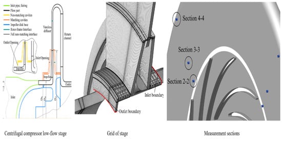
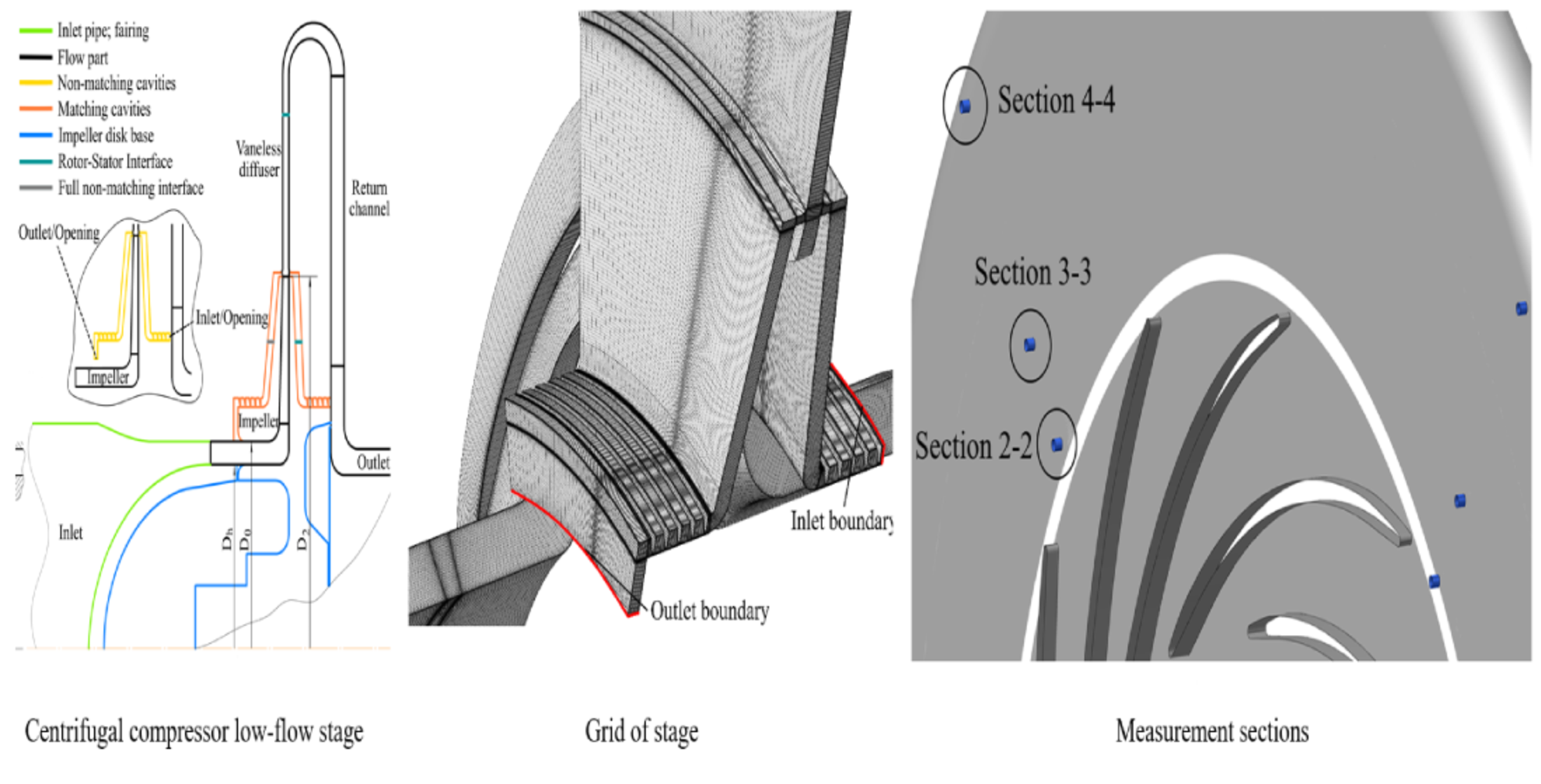
The direction of gas leaks during the intermediate stage is shown in
Figure 1 by red arrows. In the calculative gas-dynamic system of leaks through gaps and labyrinth seals and flow in the flow part, an equilibrium state is established, which causes even greater gas overheating due to flow closed circuits, “impeller exit—impeller cover gap—impeller entrance” and “exit from the reverse guide vane unit—the clearance of the main disk of the impeller—the entrance to the vaneless diffuser”. Therefore, from the point of view of the most calculated heat exchange, the most significant consideration is the gap between the impeller and the stator. During the process of compression, in a real centrifugal stage, gas heating by leaks through the labyrinth seals is certainly present, but less intense due to the presence of gas heat exchange with the impeller disks and the stator elements. It is also worth noting that according to the results from many works’ analyses [
8,
9,
10,
11,
12], there is a tendency to overstate the internal pressure according to the results of modeling the flow in the centrifugal compressor. One of the reasons for this overstatement of internal pressure, directly related to the numerical model, is the lack of heat exchange with the constructive elements when defining adiabatic walls. In the literature, there are examples described of modeling the flow in the centrifugal compressor stage, taking into account heat transfer [
13,
14,
15,
16,
17,
18,
19,
20,
21]. These works were devoted to both conjugate heat exchange and a simplified method for heat exchange modeling. The conclusion of the main publications’ analyses is that there is a general lack of knowledge regarding the prevalence of an approach for heat exchange modeling in applied compressor production tasks. On the one hand, the results of this research follow general ideas of the heat exchange physical foundations, on the other hand, it is difficult to verify the numerical models used with real facility and interpret the corresponding calculated results. In addition, the issue of tuning and numerical gas-dynamic model creation taking into account heat exchange is not considered, and therefore there are no relevant recommendations.
2.2. Object and Heat Exchange Calculation Methods
This paper considers the heat exchange accounting issue for a low-flow stage with the help of two main methods, i.e., coupled heat exchange and a simplified method. The influence of heat exchange on the calculated stage gas-dynamic characteristics is considered. Modeling is carried out with the Numeca Fine/Turbo software package. The presented studies are a part of a multilateral detailed analysis of the CC low-flow stage modeling problem and serve as the basis for creating a calculation model of the flow parts low-speed stage, taking into account its main features. The objective of this research was to model the SVD-1 stage of a low-flow CC with a conditional flow coefficient Փ = 0.008 and a theoretical head coefficient ψ
t = 0.48. The conditional flow coefficient is determined by the following formula:
where
is mass flow, ρ*
in is total density in stage inlet, D
2 is impeller outlet diameter, and u
2 is impeller circumferential speed.
The stage was developed and tested at the Department of “Compressor, Vacuum and Refrigeration equipment” of the Peter the Great St. Petersburg Polytechnic University. The sketch of the level is shown in
Figure 1a.
There are several approaches to heat exchange modeling; the two main approaches are as follows:
- 1.
For conjugate heat exchange, in addition to calculating the gas flow, the heat exchange of the flow with washed solids is modeled. For a centrifugal compressor, these solid washable bodies are the disks of the impeller, diaphragms, and the housing. The task statement implies the setting of boundary conditions on the external surfaces of solids that do not border the gas-dynamic path of the stage. One of the factors limiting correct conjugate heat exchange modeling is the unknown boundary conditions on the external solid surfaces. In order to include the heat transfer from the stator and housing elements to the environment, it is necessary to have either the temperature distribution on the external surfaces or the heat transfer coefficient. In most cases of modeling, these parameters are unknown and can be approximately calculated by thermal analysis of the flow part construction.
However, for an experimental stage consideration, in order to measure and calculate the total pressure more accurately, a high level of thermal insulation of the housing elements must be ensured. Accordingly, it is accepted as an assumption that, in the system, “flow parts-housing elements” thermal equilibrium is established with temperature distribution close to the flow temperatures.
- 2.
Simplified accounting of heat exchange involves setting one of several options applied to the flow part walls, i.e., temperature distribution, heat flux, or heat transfer coefficient. In the task of modeling the working process of the centrifugal compressor, simplified accounting of heat exchange seems to be simpler and more convenient, since there is no need to calculate the temperature distribution in solids. This greatly simplifies the mathematical and grid models. With a justified approach, simplified heat transfer calculation can provide acceptable engineering accuracy. An option, considered in this paper, is setting the indicative temperatures of the flow part walls according to the results of the conjugate heat exchange calculation.
One of the main tasks is to ensure the correct temperature distribution in the near-field areas, which refers to the prevention of incorrect leaks’ overestimation, which affects the gas-dynamic characteristics of the stage. Therefore, for similar tasks, it seems possible, in the first approximation for the surfaces forming the gaps, to set the temperature distributions that describe the probable distribution based on the calculated temperatures in the main flow parts. After that, the set temperature distributions are iteratively refined until a steady-state acceptable solution is reached.
2.3. Computational Fluid Dynamics (CFD) Setup
For modeling the conjugate heat exchange in the grid model of the gas-dynamic flow part, mesh models of solids are additionally created in accordance with the limiting inverter flow part surfaces. Therefore, there are about 4 million mesh elements in the main flow part (impeller, diffuser), 2.5 million in the cavities, and 2.5 million in the solid bodies. A three-dimensional (3D) mesh with connections defined can be automatically generated via NUMECA module Autogrid5. The full mesh model of the SVD-1 stage is shown in
Figure 1b.
The physics setup is steady-state Reynolds-averaged Navier–Stokes equations with Spalart–Allmaras turbulence model with extended wall function (for the surface roughness simulation). The fluid is atmospheric air with the corresponding parameters. As boundary conditions, total pressure and total temperature with flow direction at the inlet and mass flow rate at the outlet are applied. The conditional Mach number, Mu2, equals 0.59 (10,960 rpm of rotor for the considered task). The heat transfer coefficient is set for the details of the experimental bench of the SVD-1 stage, α = 46 W/(m∙K) is accepted.
The simulation convergence was achieved in 4000 iterations for the conjugate heat exchange task and about 700 iterations (with CPU booster feature, which accelerated convergence up to 5 times and could not be applied for the conjugate simulation) for adiabatic walls and simplified heat exchange. The convergence criteria are a −3 order of magnitude and less of the main equation residual and equality of mass flow rate at the inlet and the outlet; the main criterion is stabilization of flow and gas-dynamic parameters (efficiency, pressure ratio), because of long convergence of leaks through the labyrinth seals and heat transfer parameters.
The computational result is automatically processed with python scripts via NUMECA module CFView. The processed parameters and criteria correspond with the experimental data for building gas-dynamic characteristics.
3. Results
3.1. General Result Overview
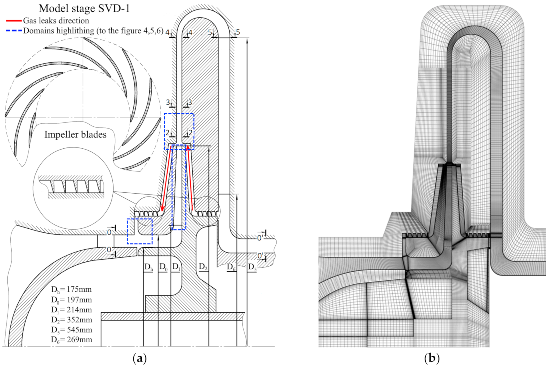
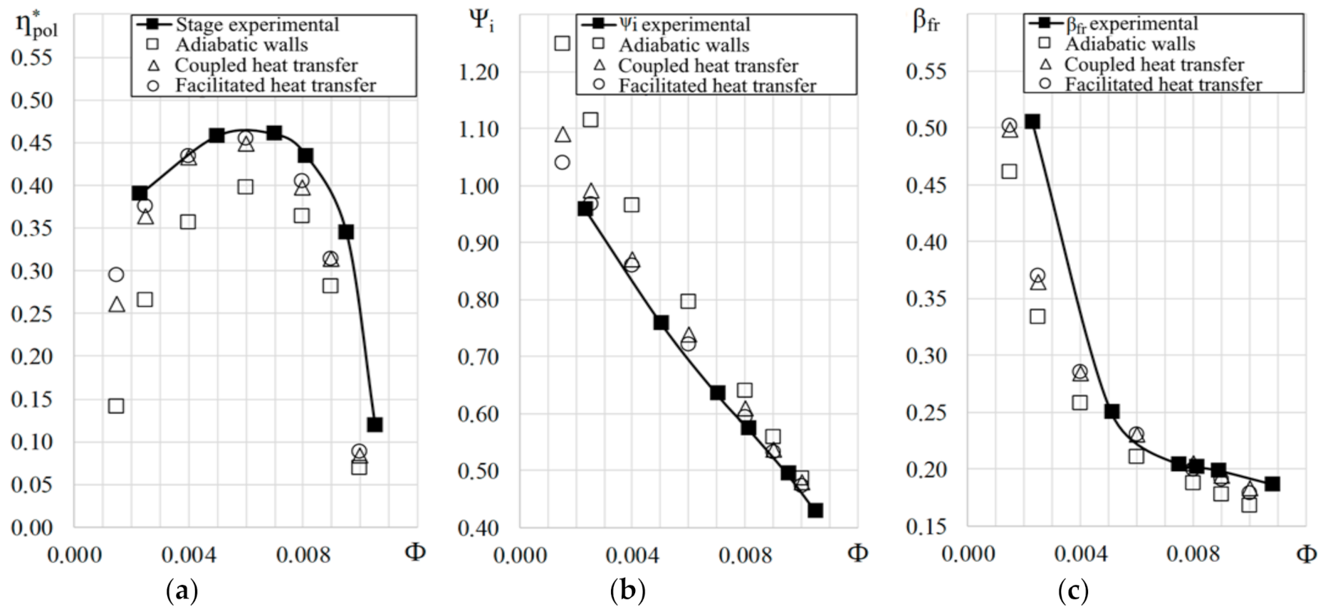
The modeling results of the working process using the conjugate heat exchange method and the simplified heat exchange accounting method are presented in
Table 1 and
Figure 2 in the form of the following calculated and experimental gas-dynamic characteristics of the researched stage: polytropic efficiency η*
p, internal pressure coefficient ψ
i, and disk friction coefficient β
fr.
According to the gas-dynamic characteristic efficiency of the stage in
Figure 2, it is possible to estimate the effect of heat removal from the frontier areas as follows: The importance of polytropic efficiency value increases by 5% for optimal mode with a relative decrease in the temperature difference, ΔT, of the steps by 8%. In the area of loaw productivity, the impact of heat exchange is the most significant due to an increase in the pressure ratio that leads to an increase in leaks, as well as an increase in the discharge temperature. While moving to the right branch of the gas-dynamic characteristics, that is, in the area of a higher flow rate, the effect of heat exchange is reduced. It is connected with the pressure ratio reduction, reducing the discharge temperature.
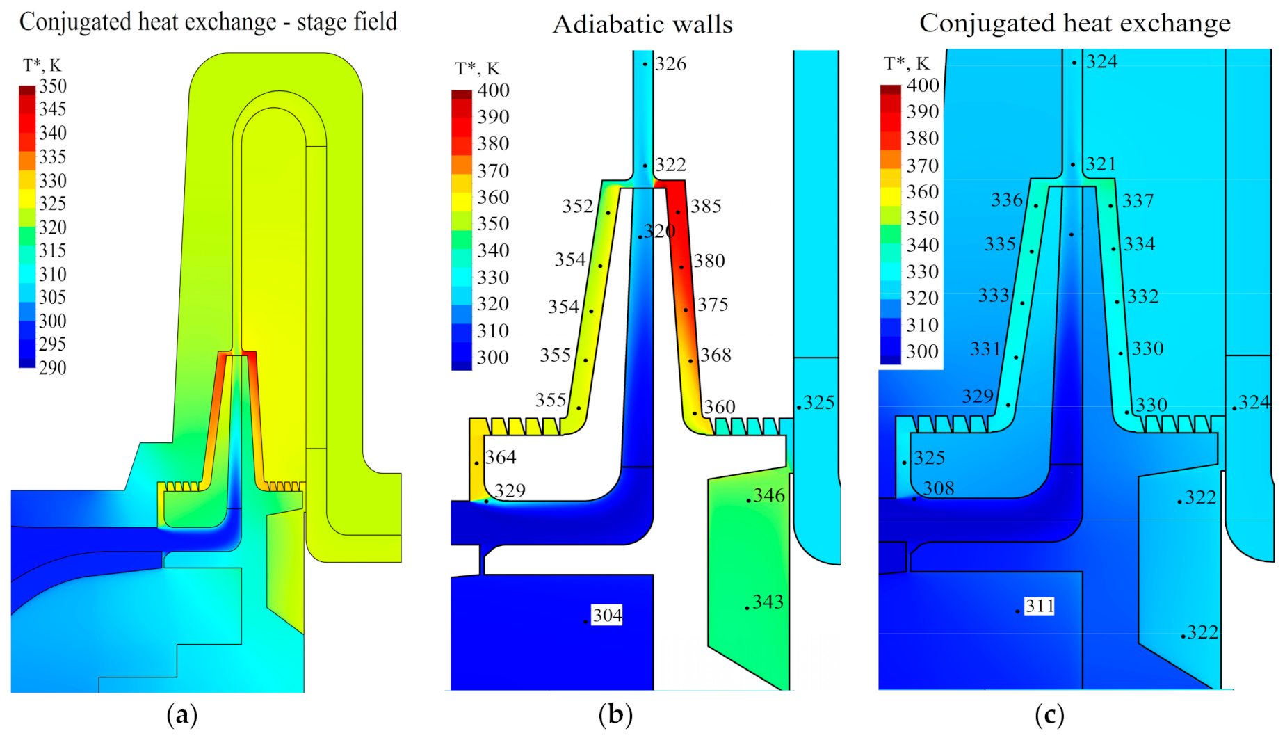
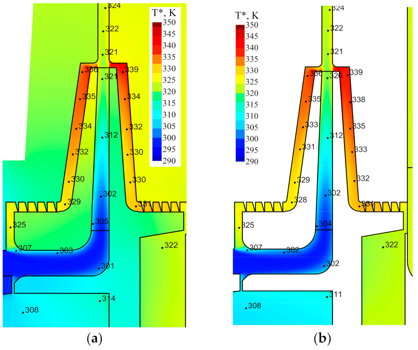
Figure 3a shows the meridian cross-section averaged over the circumferential coordinate at the optimal mode for a model with a conjugate heat transfer in the temperature range up to 350 K, and
Figure 3b,c shows the comparison of the temperature fields in the disk gaps and seals for model variants with adiabatic walls and with a conjugate heat exchange, accordingly, in the temperature range up to 400 K.
Reducing temperature difference at the stage of the inlet and the outlet due to heat exchange is naturally reflected on the internal pressure of the stage. Heat transfer accounting essentially brings together the calculated and experimental internal pressure coefficients, as well as it changes the incline of the gas-dynamic characteristics in accordance with the change in the effect of heat transfer when deviating from optimal mode. Overpressure according to the simulation results in the optimal mode, is reduced from 14% to 4.7%, but in the low-performance mode it is reduced from 18% to 5.5%, and in the high-performance mode it is reduced from 5.5% to 2.5%.
3.2. Temperature Distribution of the Impeller Inlet Analysis
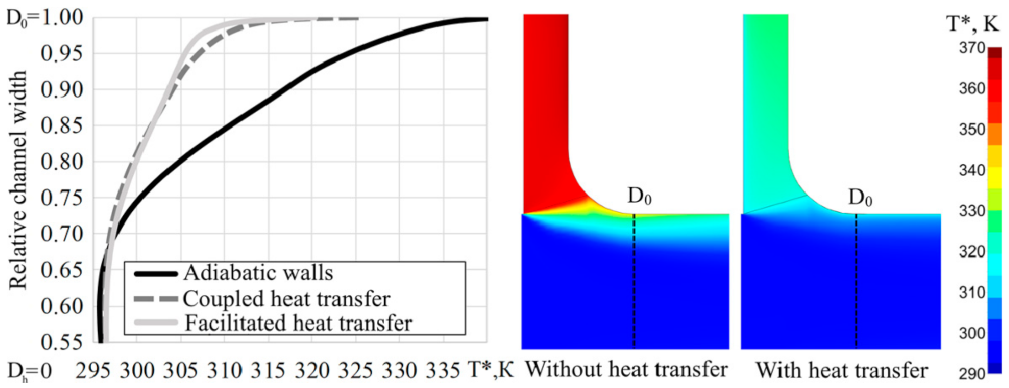
Analysis of temperature profiles at the inlet to the RC after mixing the leak with the main flow (highlighted on
Figure 1a) excluding and including the heat exchange (
Figure 4) allows us to make conclusions about the significant decrease in the temperature of leakage on the covering disk when accounting for the heat exchange, as well as about the qualitatively close conjugate and simplified heat exchange modeling results. The temperature of the gas leaking on the covering disk, due to the effect of heat exchange, is reduced by 40 °C, which corresponds to a decrease in the difference of temperatures of leakage and the main disk by 2.4 times as compared with the case of adiabatic walls. Thus, the peripheral flow, which occupies 30% of the height of the impeller passage, is heated by approximately 7 K instead of 17 K.
3.3. Impeller Temperature Distribution Analysis
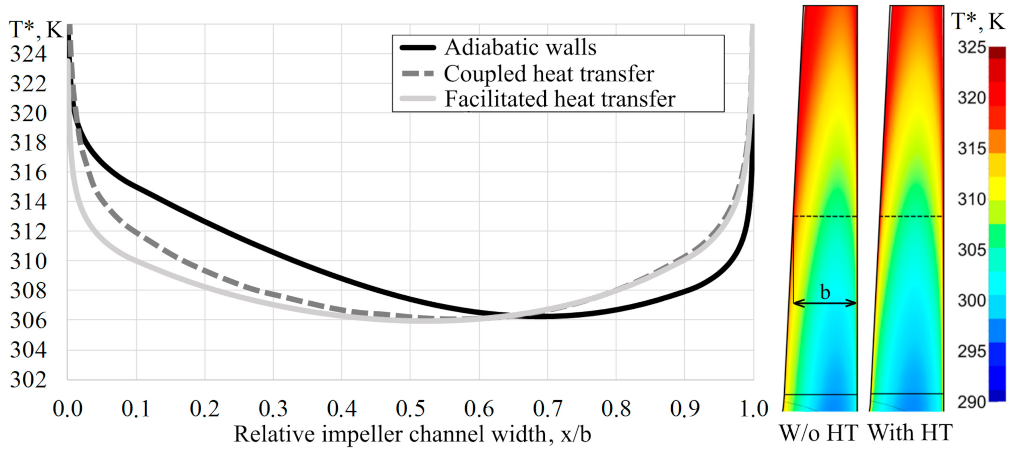
Consideration of the temperature profile on the width of the impeller passage (highlighted in
Figure 1a) at the x/b coordinate (x = 0 on the covering disk, x = b on the main disk) (
Figure 5) on the diameter (D
1 + D
2)/2 allows us to draw a conclusion about a significant distortion of the temperature profile for the variant of the adiabatic walls and the minimum temperature offset in the direction to the main disk. For both versions of the models accounting the heat exchange, the effect of heating the gas flow on the sleeve surface from the main disk where the temperature is approximately 2 °C higher than for the case of adiabatic walls is noticeable. Thus, the temperature profile, when it takes into account heat transfer, is close to symmetrical, relative to the center of the impeller passage.
3.4. Temperature Distribution of the Diffuser Inlet Part Analysis
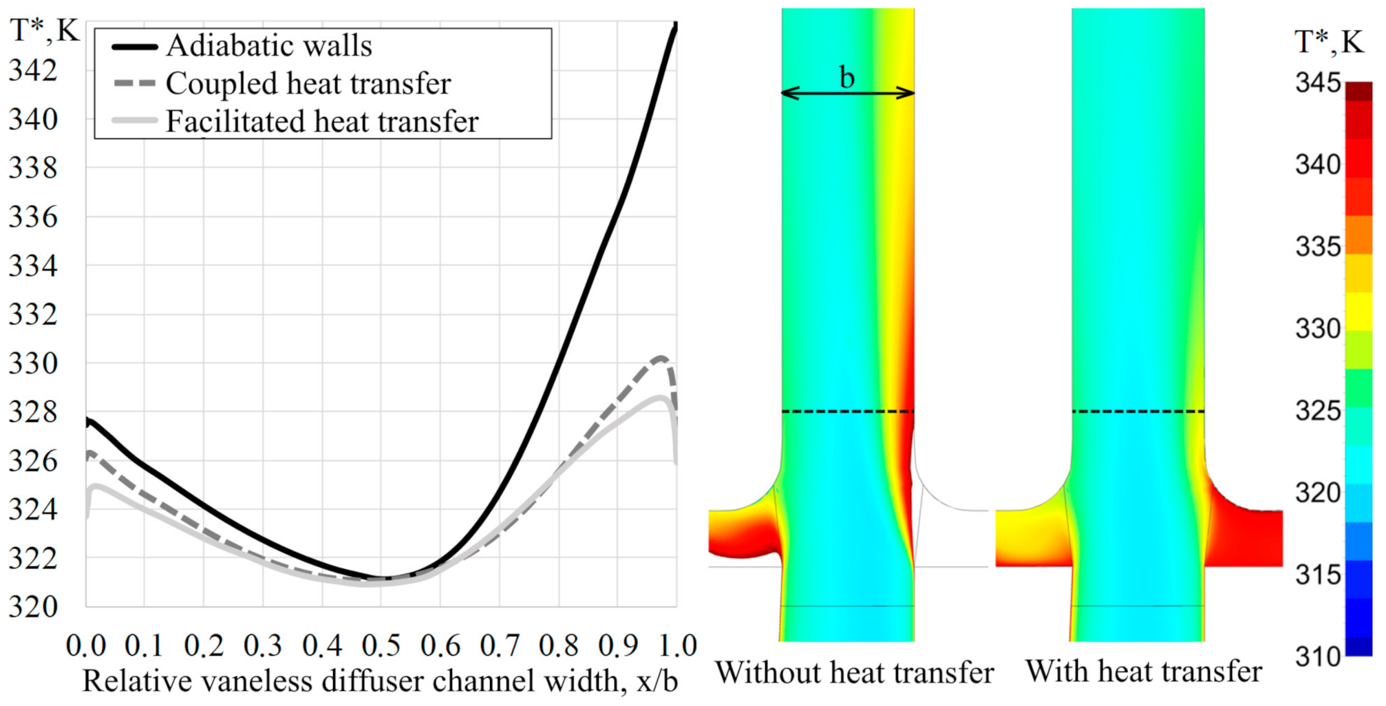
The final conclusions can be made by analyzing the temperature profile when entering into the diffuser (highlighted in
Figure 1a) at the x/b coordinate (
Figure 6). Heat dissipation is particularly noticeable when analyzing the leakage on the main disk, which takes approximately the same 30% of the passage as at the entrance to the impeller for leakage through the covering disk. Flow heating near the hub in the diffuser for the version with heat exchange is only 4 K, while, for the version with adiabatic walls, it is 11 K. In this case, the flow core at the entrance to the diffuser has the same temperature as that of the modeling with adiabatic walls. This shows that accounting for heat exchange does not have an impact on the temperature in the core of the impeller stream. However, in the case of the calculation with heat exchange, a reduction in the temperature of the peripheral flow occurs at the entrance to the diffuser of approximately 1.3 K, and for the sleeve, respectively, of 7 K. This decrease in temperature at further mixing leaks with the main flow, as well as the effect of the flow heating by the intermediate diaphragm are expressed as a cumulative decrease in temperature at the outlet from the diffuser of 2.1 degrees. This corresponds to an increase in polytropic efficiency in the optimal mode for the stage under consideration of approximately 5% and to a reduction in calculated internal pressure of 9.5%.
3.5. Comparison Temperature Distribution of the Two Considered Heat Exchange Types
Considering the two methods of heat exchange modeling, it can be noted that the results match well enough when the temperature is completely transferred from the model with conjugate heat exchange to a model with direct parameter setting of wall heat exchange.
Figure 7 shows a comparison of the temperature fields in the impeller for the cases of conjugate heat exchange modeling and transfer of temperature distributions on the surface for simplified modeling. The results show that the calculation with the temperature transfer for simplified modeling describes the temperature fields in the gaps close to the model with a coupled heat exchange. The observed difference in GDC is due to the inaccuracy of modeling heat exchange in the diffuser and return guide vane, as well as a manual approximation of the data when transferring distributions.
4. Discussion
The simplified method of heat exchange can be used for evaluating calculations since, as it is shown above, the main goal for the model of the economical stage is the consideration of removal of heat from the gap to reduce heating of gas in the impeller and diffuser. Therefore, the method can be used for quantitative and qualitative calculation of the temperature field in the gaps without more preliminary labor-intensive and resource-intensive calculation of the model with conjugate heat exchange. The essence of the simplified method is in the iterative calculation and correction of the temperature distributions to ensure temperature equilibria in FP surfaces and in the gaps.
The task is repeatedly solved until the correct temperature level in the gaps is provided if the temperature of the core of the flow in the impeller is constant according to the calculation with the adiabatic walls. Thus, it takes into account the conditional heat sink from the gap and the incorrect influence of leaks on the discharge temperature is excluded, which is important for the systems with high leaks and thermal friction energy.
However, it should be understood that both methods of heat exchange accounting are essentially corrective and clarifying. Considering a real compressor process machinery, the heat transfer by FP surfaces and housing with the environment is more complex and uncertain, and to simulate this process correctly in conjunction with gas-dynamic calculation is extremely difficult, without having information about the parameters of all the elements involved in the heat exchange.
In one way or another, heat exchange for the low-waste stage of a CC, when considering the issue of accurate modeling, should be taken into account. Accounting for heat exchange for the economical stage principally affects the temperature distribution in the impeller and the diffuser due to the large values of leakage through the gaps of the disks and heating gas in the main FP, which in total affects the final temperature; the efficiency of a stage, inner pressure, and the friction discs; and the calculated axial force. The simplified heat exchange modeling option, by setting approximate temperature fields calculated from the primary computation with conjugate heat exchange or, iteratively, from the estimated calculation with adiabatic walls, is submitted to be rational.
In general, simulation of conjugated heat exchange for the calculation of FP CC is a complex task which goes beyond conventional engineering approaches. This solution should only be used in the most urgent situations, and the decision to apply this solution must be made attentively, carefully, and reasonably, because the task is time-consuming and complex from the point of view of the physics of the considered processes and creating, preparing, and configuring a numerical model.
Author Contributions
Conceptualization, Y.K. and S.K.; Methodology, S.K. and V.I.; Software, S.K. and A.D.; Validation, S.K. and A.A.; Formal Analysis, Y.K., S.K., and A.Y.; Investigation, Y.K., S.K., and I.Y.; Writing—original draft preparation, S.K. and M.H.N.; Writing—review and editing, S.K. and Y.K.; Supervision, Y.K. All authors have read and agreed to the published version of the manuscript.
Funding
The research is partially funded by the Ministry of Science and Higher Education of the Russian Federation as part of World-Class Research Center program, Advanced Digital Technologies (contract no. 075-15-2020-934 dated 17 November 2020).
Conflicts of Interest
The authors declare no conflict of interest.
Nomenclature
| CFD | Computational fluid dynamics |
| CC | Centrifugal compressor |
| FP | Flow part |
| GDC | Gas-dynamic characteristics |
| D | Diameter, m |
| u2 | Angular velocity at impeller exit |
| T* | Total temperature, K |
| ρ | Density, kg/m3 |
| Massflow, kg/s |
| Mu2 | Conditional Mach number |
| α | Heat exchange coefficient, W/(m∙K) |
| Φ | Conditional flow coefficient |
| βfr | Impeller disk friction coefficient |
| ψi | Internal pressure coefficient |
| ηpol | Polytropic efficiency |
References
- Aksenov, A.A.; Danilishin, A.M.; Dubenko, A.M.; Kozhukhov, Y.V. Development of the virtual experimental bench on the basis of modernized research centrifugal compressor stage test unit with the 3D impeller. IOP Conf. Ser. Mater. Sci. Eng. 2017, 232, 012042. [Google Scholar] [CrossRef]
- Sugimura, K.; Kobayashi, H.; and Nishida, H. Design Optimization and Experimental Verification of Centrifugal Compressors with Curvilinear Element Blades. In ASME Turbo Expo 2012: Turbine Technical Conference and Exposition, Volume 8: Turbomachinery, Parts A, B, and C; Paper No. GT2012-69162; ASME: New York, NY, USA, 2012. [Google Scholar] [CrossRef]
- Neverov, V.V.; Kozhukhov, Y.V.; Yablokov, A.M.; Lebedev, A.A. Optimization of a centrifugal compressor impeller using CFD: The choice of simulation model parameters. IOP Conf. Ser. Mater. Sci. Eng. 2017, 232, 012037. [Google Scholar] [CrossRef]
- Noman Danish, S.; Ud-Din Khan, S.; Umer, U.; Rehman Qureshi, S.; Ma, C. Performance Evaluation of Tandem Bladed Centrifugal Compressor. Eng. Appl. Comput. Fluid Mech. 2014, 8, 382–395. [Google Scholar] [CrossRef]
- Aksenov, A.; Kozhukhov, Y.; Sokolov, M.; Simonov, A. Analysis and modernization of real gas thermodynamic calculation for turbocompressors and detander units. MATEC Web Conf. 2018, 245, 09005. [Google Scholar] [CrossRef]
- Bogdanets, S.; Blinov, V.; Sedunin, V.; Komarov, O.; Skorohodov, A. Validation of a CFD model of a single stage centrifugal compressor by local flow parameters. CEUR Workshop Proc. 2018, 2298, 1–14. [Google Scholar]
- Kartashov, S.V.; Kozhukhov, Y.V. Justification of the Choice of the Computational Domain in Problems Simulation of Viscous Flow in Low-Flow Stages of a Centrifugal Compressor; Refrigeration Equipment, 1; Refrigerating Appliances: Luxembourg, 2020; pp. 22–27. [Google Scholar]
- Xi, G.; Wang, Z.; Li, X.; Wang, S. Aerodynamic Design and Experimental Validation of Centrifugal Compressor Impellers with Small Flow Rate. In ASME Turbo Expo 2009: Power for Land, Sea, and Air, Volume 7: Turbomachinery, Parts A and B; ASME: New York, NY, USA, 2009. [Google Scholar] [CrossRef]
- Matas, R.; Syka, T.; Luňáček, O. Numerical and experimental modelling of the centrifugal compressor stage—Setting the model of impellers with 2D blades. EPJ Web Conf. 2017, 143, 2073. [Google Scholar] [CrossRef]
- Sundström, E.; Kerres, B.; Sanz, S.; Mihăescu, M. On the Assessment of Centrifugal Compressor Performance Parameters by Theoretical and Computational Models. In ASME Turbo Expo 2017: Turbomachinery Technical Conference and Exposition, Volume 2C: Turbomachinery; ASME: New York, NY, USA, 2017. [Google Scholar] [CrossRef]
- Danilishin, A.; Kozhukhov, Y.; Neverov, V.; Malev, K.; Mironov, Y. The task of validation of gas-dynamic characteristics of a multistage centrifugal compressor for a natural gas booster compressor station. AIP Conf. Proc. 2017, 1876, 020046. [Google Scholar] [CrossRef]
- Pecnik, R.; Rinaldi, E.; Colonna, P. Computational Fluid Dynamics of a Radial Compressor Operating with Supercritical CO2. J. Eng. Gas Turbines Power 2012, 134, 122301. [Google Scholar] [CrossRef]
- Dragan, V. Centrifugal compressor efficiency calculation with heat transfer. IIUM Eng. J. 2017, 18, 225. [Google Scholar] [CrossRef]
- Bohn, D.; Heuer, T.; Kusterer, K. Conjugate Flow and Heat Transfer Investigation of a Turbo Charger. J. Eng. Gas Turbines Power 2005, 127, 663–669. [Google Scholar] [CrossRef]
- Gu, L.; Zemp, A.; Abhari, R.S. Numerical Study of the Heat Transfer Effect on a Centrifugal Compressor Performance. Proc. Inst. Mech. Eng. Part C J. Mech. Eng. Sci. 2015, 229, 2207–2220. [Google Scholar] [CrossRef]
- Moosania, S.M.; Zheng, X. Comparison of Cooling Different Parts in a High Pressure Ratio Centrifugal Compressor. Appl. Sci. 2017, 7, 16. [Google Scholar] [CrossRef]
- Burke, R.; Copeland, C.; Duda, T.; Reyes-Belmonte, M. Lumped Capacitance and 3D CFD Conjugate Heat Transfer Modelling of an Automotive Turbocharger. In ASME Turbo Expo 2015: Turbine Technical Conference and Exposition, Volume 8: Microturbines, Turbochargers and Small Turbomachines; Steam Turbines; ASME: New York, NY, USA, 2015. [Google Scholar] [CrossRef]
- Lei, V.M.; Kawakubo, T. A Fast Method for Conjugate Heat Transfer Analysis of Centrifugal Compressor. In ASME 2007 International Mechanical Engineering Congress and Exposition, Volume 8: Heat Transfer, Fluid Flows, and Thermal Systems, Parts A and B; ASME: New York, NY, USA, 2007. [Google Scholar] [CrossRef]
- Borm, O.; Balassa, B.; Kau, H.P. Comparison of different numerical approaches at the centrifugal compressor radiver. In Proceedings of the 20th ISABE Conference, Gothenburg, Sweden, 12–16 September 2011. [Google Scholar]
- Heuer, T.; Engels, B.; Wollscheid, P. Thermomechanical Analysis of a Turbocharger Based on Conjugate Heat Transfer. In ASME Turbo Expo 2005: Power for Land, Sea, and Air, Volume 1: Turbo Expo; ASME: New York, NY, USA, 2005; Volume 46997, pp. 829–836. [Google Scholar] [CrossRef]
- Roclawski, H.; Oberste-Brandenburg, C.; Böhle, M. Conjugate Heat Transfer Analysis of a Centrifugal Compressor for Turbocharger Applications. In Proceedings of the 16th International Symposium on Transport Phenomena and Dynamics of Rotating Machinery, Honolulu, HI, USA, 10–15 April 2016; hal-01884259. Available online: https://hal.archives-ouvertes.fr/hal-01884259 (accessed on 20 November 2020).
| Publisher’s Note: MDPI stays neutral with regard to jurisdictional claims in published maps and institutional affiliations. |
© 2020 by the authors. Licensee MDPI, Basel, Switzerland. This article is an open access article distributed under the terms and conditions of the Creative Commons Attribution (CC BY) license (http://creativecommons.org/licenses/by/4.0/).


 ,
, 


