Article

Robust Geometries for Second-Harmonic-Generation in Microrings Exhibiting a 4-Bar Symmetry

1
Nanoscience Laboratory, Departement of Physics, University of Trento, Via Sommarive 14, 38123 Povo, Trento, Italy
2
Centre for Materials and Microsystems, Fondazione Bruno Kessler, Via Sommarive 18, 38123 Povo, Trento, Italy
3
CNR-INO, Istituto Nazionale di Ottica, Via Campi Flegrei 34, 80078 Pozzuoli (NA), Italy
*
Author to whom correspondence should be addressed.
Appl. Sci. 2020, 10(24), 9047; https://doi.org/10.3390/app10249047
Submission received: 23 November 2020 / Revised: 10 December 2020 / Accepted: 14 December 2020 / Published: 17 December 2020
(This article belongs to the Section Optics and Lasers)

Abstract

:

Featured Application

The proposed microring geometries are suited to engineer a source of new frequencies or an integrated quadratic frequency comb source which can be used for several applications, e.g., metrology, sensing, radio-on-fiber, etc.

Abstract

Microring resonators made of materials with a zinc-blend or diamond lattice allow exploiting their 4-bar symmetry to achieve quasi-phase matching condition for second-order optical nonlinearities. However, fabrication tolerances impose severe limits on the quasi-phase matching condition, which in turn degrades the generation efficiency. Here, we present a method to mitigate these limitations. As an example, we studied the geometry and the pump wavelength conditions to induce the second-harmonic generation in silicon-based microrings with a second-order susceptibility χ z x y ( 2 ) 0 . We found the best compromises between performances and experimental requirements, and we unveil a strategy to minimize the impacts of fabrication defects. The method can be easily transferred to other material systems.

1. Introduction

Ranging from the frequency conversion to photon pair emission, the second-order nonlinear phenomena are fundamental tools in integrated photonics. The choice of the material to generate this nonlinear conversion depends on the specific application. An application which is of our interest is the quadratic comb generation [1].
Optical frequency combs (OFCs) are light sources whose spectra contain thousands of equally spaced laser lines and have revolutionized precise optical frequency measurements. The self-referencing allowed by octave spanning OFCs was even awarded with the Nobel Prize in Physics in 2005. In 2015, optical frequency comb generation has been demonstrated in silicon microring resonators by using four wave mixing and self-phase modulation [2]. Due to these nonlinear processes, the frequency comb generation was limited in its frequency span. To extend this span beyond one octave, the use of both second-order and third-order nonlinearities was shown in MgO:LiNbO 3 microcavities [3]. In fact, second-order nonlinearities can directly produce simultaneous octave-distant OFCs with intracavity phase modulation. Via cascaded second-order processes, they enlarge the generated frequency spectrum in these "quadratic comb" sources [4,5,6,7]. Critical in this approach is the use of the second-order nonlinearities. Therefore, to use a material to achieve a quadratic comb source, it is mandatory that the same material shows second-harmonic generation (SHG), which in turn can be used as a tool to scout for the best material for quadratic OFCs by measuring the second-order nonlinear dielectric susceptibility χ ( 2 ) of materials.
A large χ ( 2 ) does not suffice to make the material suitable for quadratic comb applications in integrated photonics. For instance, thanks to its ferroelectric properties, lithium niobate can achieve a high χ ( 2 ) but monolithic integration is difficult [8,9]. Efficient SHG was reported in III–V semiconductors, such as AlN [10] and GaN [11]. Indeed, GaAs, InP, and their alloys have large χ ( 2 ) values and can be integrated in small photonic chips, even though their mass manufacturing is still challenging [12,13,14]. With respect to integration, silicon or silicon-based materials are the preferred platform [15]. However, silicon is a centro-symmetric material and does not show any second-order nonlinearity in the dipole approximation [16]. However, by strain [17,18], by alloying, as in silicon nitride [19], and by applying a controlled DC electric field [20,21], SHG has been reported. Even though its origin is still debated—a strain-induced χ ( 2 ) [22] or an effective χ ( 2 ) caused by a dressed third-order nonlinear dielectric susceptibility χ ( 3 ) [18]—this enables the potential of silicon for quadratic OFCs.
It is therefore the aim of this paper to discuss the design of a microring resonator that shows SHG for a range of parameter variations which is representative of the typical fabrication tolerance in integrated photonics. We want to propose a method which yields high generation efficiency despite the uncontrolled variations in the microring resonator geometry. The SHG in the microring resonator is allowed by the quasi-phase matching due to the typical 4-bar symmetry in a ring made of a zinc-blend or a diamond lattice material (details in Appendix B). The use of this symmetry has been already reported and discussed in many papers, such as [23]. As a model system we used silicon leveraging the reports on strained silicon or electric-field-induced SHG without entering into the debate on its origin. We simply assumed that a χ z x y ( 2 ) element was present in the studied system. We studied various microresonator geometries, allowing SHG to find the best compromise between performances and experimental requirements. We optimized the geometries while also taking into account the random fabrication defects. This paper is organized as follows. First, we present the method and the general results. Then, through the calculation of the conversion efficiency, we choose the best geometries for SHG. Finally, the study of the previous results leads to the demonstration of the existence of geometries which are robust against fabrication imperfections. Despite the results being for a typical silicon microring resonator, the proposed methodology can be easily extended to other materials.

2. Conditions for SHG

2.1. Method

As a model material, we study SHG in a Si microring (Figure 1). As proposed in [18] and due to good knowledge of the material parameters, we consider a silicon waveguide with a thin cladding of Si 3 N 4 of thickness e S i N = 140 nm. The waveguide width in the microring is w, its thickness is e, and the internal microring radius is R i n . The light propagating in such a microring can be described by the resonant modes of the electromagnetic field. Each mode is labeled by three numbers: the planar number, q, giving the number of the electric field extrema along z; the radial number, p, giving the number of extrema along r; and the azimuthal number, m, corresponding to the number of wavelengths on one round-trip. These modes exist in two different polarizations: either the electric field is along z ( E z ) and the mode is called TM, or the magnetic field is along z ( H z ) and the mode is called TE [24]. The fundamental field (pump of wavelength λ f ) is coupled to the microring by a straight bus waveguide which is also used to collect the second harmonic (SH) field (wavelength λ S H ).
The SHG occurs if the energy and the angular momentum are conserved. The first conservation requirement is straightforward and reads as λ f = 2 × λ S H . The second one depends on which modes are coupled through the susceptibility tensor. Without loosing generality and to simplify the discussion, we assume a homogeneous second-order nonlinear tensor with a single χ z x y ( 2 ) 0 . In practice, this value of χ ( 2 ) can be set either by the proper engineering of the strain [25,26,27] or by adding properly designed p–i–n junctions across the waveguide in the ring [20]. With the assumption χ z x y ( 2 ) 0 , a H z polarized fundamental mode generates a E z polarized SH mode. The conservation of the angular momentum reads, therefore, m S H = 2 × m f + 2 , where m S H is the SH azimuthal number and m f is the pump azimuthal number (see Appendix B). This situation is similar to the quasi-phase matching condition which exploits the 4-bar symmetry [23,28].
We determine the geometries and wavelengths meeting these two requirements by finite element method simulations using the COMSOL Multiphysics software [29]. In addition, in this work we want to propose a design that can be realized and tested in our laboratory. Therefore, after a preliminary computation, we limit the study to the case q f = q S H = 1 , p f = 1 , and p S H = 3 to keep λ f < 2.6 μ m because of the available laser source in our laboratory. Moreover, the shorter wavelength limit λ f > 2.2 μ m is imposed to avoid two-photon absorption (TPA) in silicon. TPA is a process that will compete with SHG, affecting in a drastic way the conversion efficiency. For a given thickness, width, and fundamental azimuthal number, the program performs iterations modifying the microring radius until the SHG conditions are satisfied. The refractive index dispersions used in the modeling for the different materials are taken from experimental ellipsometry measurements and are given in Appendix A.

2.2. Results

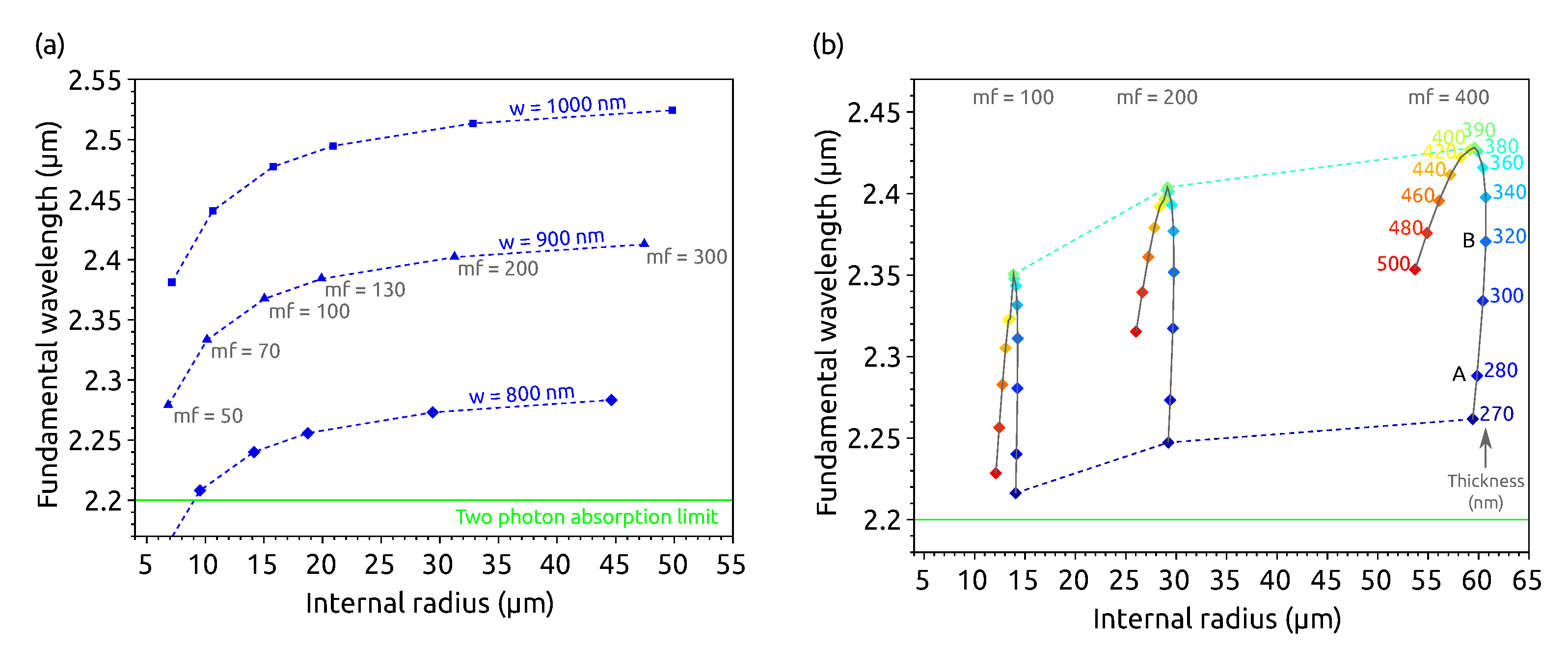
Figure 2a shows the fundamental mode wavelengths that satisfy the SHG conservation laws for a fixed waveguide thickness ( e = 280 nm) and different waveguide widths and fundamental mode azimuthal numbers. It is interesting to note that many geometries are available to generate a SH using a pump wavelength longer than 2.2 μ m, which is the limit to prevent two-photon absorption (TPA) [30]. Note that we use dashed curves in the figure to underline that the SHG conditions are not continuous, since the microrings have separate resonances—i.e., the azimuthal number is an integer. We can see that along one curve, the radius increases with m f , which is consistent with the fact that more wavelengths have to fit on one round-trip. Moreover, the curves are steeper for small radii and saturate for large radii. This can be easily understood, since when the radius becomes large, the ring resembles more a straight waveguide where the angular momentum conservation is replaced by the linear momentum conservation which does not depend on the radius. Besides, the three curves show that the fundamental wavelength is longer for a given m f when the width increases. This is consistent with the fact that when w is larger, the effective index increases and thus the wavelength lengthens to keep the azimuthal number constant.
Figure 2b is a complement of (a) showing the thickness’s influence. This time the width is fixed to w = 800 nm and the waveguide thickness is varied. We can observe that the variations of the radius and of the wavelength are not monotonous with the thickness. For small thicknesses, e < 400 nm, the thicker the microring, the larger the wavelength. However, for e > 400 nm, the wavelength decreases with the thickness. This evolution will be thoroughly described and explained in the fourth section. We can note that, unlike the previous evolution of λ f with R i n at fixed w and e, this time the evolution shown by the curves is continuous: for any thickness e, at a given w, an internal radius R i n and a pump wavelength λ f exist that fulfill the SHG condition.

3. Conversion Efficiency

3.1. Method

The conversion efficiency η is defined as the power ratio between the generated SH and the pump, both estimated inside the bus waveguide:
η = b 1 , S H a 1 , f 2
where b 1 , S H is the electric field amplitude of the SH mode in the waveguide after the microring and (since the fundamental mode is H z instead of E z ) a 1 , f is the magnetic field amplitude of the fundamental mode in the waveguide before the microring (Figure 1a). η gives a useful insight into which geometry should be used for SHG among the numerous possibilities previously determined.
η expression is derived from [23]:
η = 4 π 2 P i n | K | 2 α S H 2 ( 1 t S H 2 ) 1 + α S H 2 t S H 2 2 α S H t S H cos ( φ S H ) × α f 2 ( 1 t f 2 ) 1 + α f 2 t f 2 2 α f t f cos ( φ f ) 2
where P i n is the pump power inside the bus waveguide; t and α are, respectively, the transmission coefficient of the coupling for the amplitude and the transmission coefficient after one round-trip inside the microring. They are computed from the coupling quality factor Q c p l , and the intrinsic one Q i n t , by Q i = π m x 1 x where x = α if i = i n t and x = t if i = c p l [31].
K is the overlap between the fundamental and the SH modes, in the case of a phase mismatch Δ m = m S H 2 m f , where m S H and m f are pseudo-azimuthal numbers computed by linear interpolation corresponding to non-resonant wavelengths. The pseudo-azimuthal numbers also allow to evaluate the phase: φ = 2 m π . According to [23] the overlap reads:
K = K 2 + × exp [ i ( Δ m + 2 ) π ] × s i n c [ ( Δ m + 2 ) π ] + K 2 × exp [ i ( Δ m 2 ) π ] × s i n c [ ( Δ m 2 ) π ]
where K 2 ± is the field overlap in the case of the phase matching:
K 2 ± = i 4 n f 2 2 μ 0 ω S H m S H N S H 1 m f N f ( χ z x x ( 2 ) ± 2 i χ z x y ( 2 ) + χ z y y ( 2 ) ) r i n g r E z S H * m f H z f r ± H z f r 2 d r d z
where χ z x x ( 2 ) = χ z y y ( 2 ) = 0 and χ z x y ( 2 ) is factorized out of the integral due to the assumption of a uniform value. We assume in χ z x y ( 2 ) = 1 pm/V (which is close to the value given in [18] or in [22]). N S H is a normalization constant given by:
N S H = | E z | 2 r d S ,
whereas N f is given by Equation (5) where E z is replaced by H z .
In the following, we assume a critical coupling condition between the bus-waveguide and the microring, with the Q-factors equal to 10 4 and P i n = 1 mW. Simulations were done in the undepleted pump approximation. The assumption of a constant Q-factor is quite crude. However the main goal of this paper is to demonstrate the influence on fabrication defects on the SHG in a model system. More refined modeling for a fabricated microresonator to-be should clearly consider the geometrical dependence of the Q-factor.

3.2. Discussion

Figure 3a shows that for a fixed thickness e = 280 nm, the smaller the radius, the larger the conversion efficiency. We can also observe that η increases when the width decreases in the range 800 w 1000 nm. The evolution of η with the thickness is shown in Figure 3b where the width is fixed to w = 800 nm. Even if small radii give better efficiency, we chose to represent here the points of Figure 2b corresponding to m f = 400 (dashed line), since they are the points that will be discussed in the next section. For smaller radii, the numerical values would be different, but the shape of the curve would be similar, which makes the following discussion general. To get rid of the variation of η due to the variation of the radius, we plotted another set of points where, this time, the radius is kept as close as possible to R i n = 60 μ m while varying e (solid line). Indeed, it is not possible to fix the value of the radius for given w and e, since it must correspond to an integer for the azimuthal numbers. We observe that the variation of η with e is not monotonous for these geometries. η is maximum for e = 360 nm.
The SHG simulations allow choosing the optimal geometry by compromising between the experimental, fabrication, and theoretical requirements. For instance, Figure 3a shows that the best conversion efficiencies are obtained with small radii, but Figure 2 shows that to avoid the two-photon absorption of the fundamental mode, it is required either to choose w 900 nm for e = 280 nm, or a thick microring if the width is kept equal to 800 nm.

4. Robust Geometries against Fabrication Errors

4.1. Analysis

The goal of this analysis is to understand the shape of the curves in Figure 2b in order to look for ranges where small variations in the geometries (which are unavoidable due to the precision of the fabrication) do not change the results. Thus, the width is fixed to w = 800 nm and the resonant wavelengths are computed by varying the thickness and the internal radius. Without loosing generality, we consider the case of m f = 400 since the points are more spaced, making clearer the discussion.

4.2. General Observations

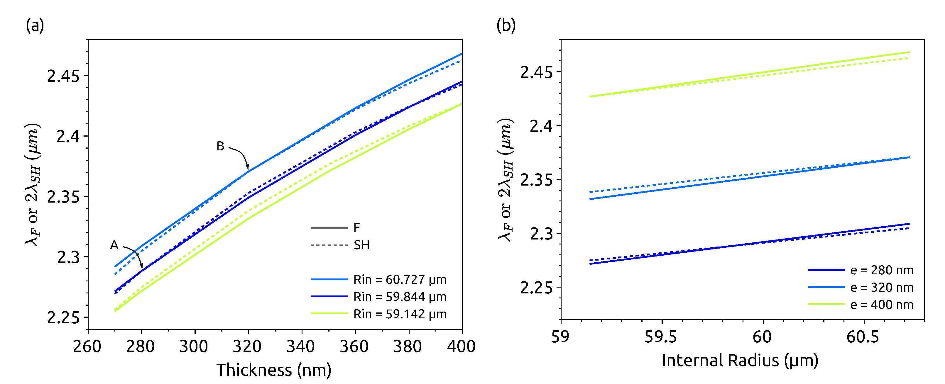
Figure 4 shows the resonant wavelengths for two families of fundamental (solid line) and SH modes (dashed line). The first one corresponds to m f = 400 , H z polarization, p = 1 , and λ f around 2.3 μ m. The second one corresponds to a SH mode with m = 802 , E z polarization, p = 3 , and λ S H around 1.15 μ m. For the sake of simplicity, the first modes are labeled F, as in fundamental, and the second one is S H , as in second harmonic, but these modes really correspond to fundamental and SH only when the energy conservation is fulfilled, i.e., only at the crossing points of the curves in the figure.
Figure 4a shows the resonant wavelengths as a function of the thickness for three different radii. We can see that when the radius increases, the wavelength increases. This is easy to understand considering the resonant wavelength expression:
λ = 2 π R n e f f m
where n e f f is the effective index, and R the mean radius of the microring. The effective index does not change much with the radius, and thus, when the radius is larger, a longer wavelength is needed to keep the azimuthal number constant. In all cases, we can also observe that the wavelength increases with the thickness. This evolution is needed to keep the azimuthal number constant, since the effective index increases with the thickness. Finally, we can see that the slope decreases with the thickness. This is understandable since, when the thickness is large enough, the mode is well confined, and thus, the effective index becomes less sensitive to the thickness variation. For the small thicknesses, the SH slope is larger than the fundamental one, while it is smaller at large thicknesses.
Figure 4b shows the resonant wavelengths with respect to the radius for three different thicknesses. We observe the same general evolutions as described before: the wavelength increases with the radius or the thickness. Nevertheless, this time, the slope for the fundamental mode is always larger than the one for the SH. Since m f is about half of m S H , it is normal to have a larger slope for the fundamental according to Equation (6).
The general shapes of the curves in Figure 4 result from the chromatic and modal dispersions. Hence, the same kind of study performed in another material where χ z x y ( 2 ) 0 would lead to the same observations. Only the values for the wavelength range, thickness, and width would change.

4.2.1. For Small Thicknesses, e < 320 nm

To interpret the shape of the curve for m f = 400 on Figure 2b, let us consider the dark blue curve in Figure 4a, corresponding to R i n = 59.844 μ m. A first crossing occurs in A at e = 280 nm and corresponds to the second blue point on the curve of Figure 2b. From this crossing point, if the thickness increases, λ S H becomes larger than λ f since the slope of the dashed line is larger than the solid one. To fulfill the energy conservation again, one can take advantage of the faster variation of λ f with the radius and increase R i n . For instance, a new SHG point is found in B for e = 320 nm and R i n = 60.727 μ m. Since both the thickness and the radius have increased to reach the new SHG situation, the wavelength is longer than the previous one as found in Figure 2b.

4.2.2. For Thicknesses Larger than 320 nm

Figure 4a shows that when e > 320 nm, the slope for the fundamental mode wavelength is larger. Thus, if the thickness increases, λ S H becomes smaller than λ f , and to fulfill the energy conservation again, the radius must be decreased. This is what is shown in Figure 2b: after e = 320 nm, R i n becomes smaller. This time, the increase in the thickness and the decrease in the radius have opposite effects on the wavelength, which fulfill the SHG conditions. Till e = 390 nm, the increase in the thickness is large enough to increase the wavelength as well. For a larger thickness, the variation of the wavelength with the thickness is too small to compensate for the radius decrease, and thus, the wavelength decreases when e increases.

4.3. Application

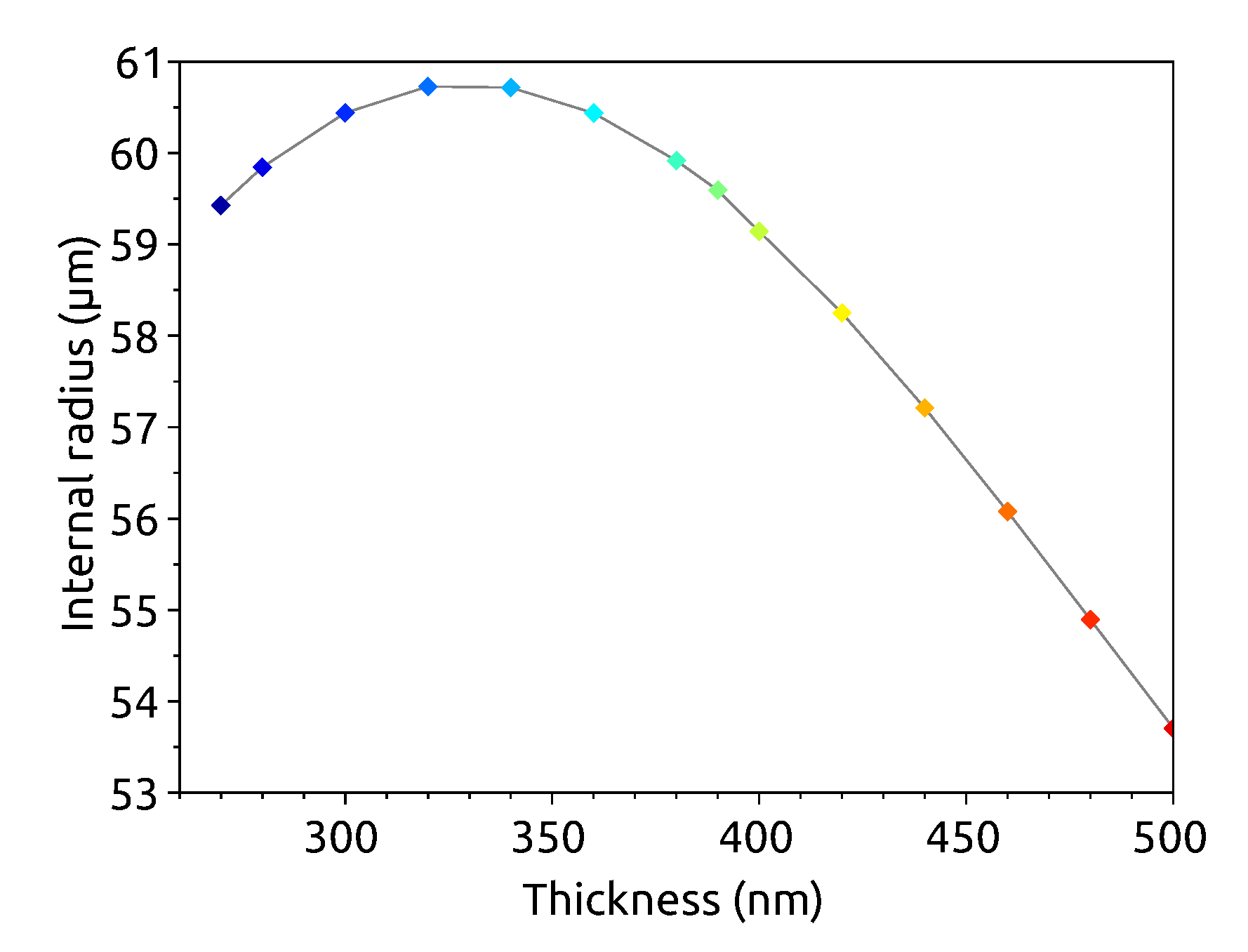
The relationship between the internal radius and the thickness values, which fulfill the SHG condition, has an interesting consequence. As shown in Figure 5, the function R i n = f ( e ) has a flat maximum around e = 330 nm, so the required microring geometry to obtain a SHG at these thicknesses has a range of radii values instead of a fixed radius value. From a practical point of view, this means that we can tolerate variations of ± 10 nm in the thickness about the selected value of 330 nm or of the radius about the selected values of 60.755 μ m without compromise on the generation efficiency. Therefore the proposed geometry is robust with respect to fabrication tolerances. Keeping in mind the general observation made in Section 4.2, the same optimization can be done for other materials. The choice of the proper geometrical parameters for the resonator and the proper pump and SH wavelengths determine the same kind of robust geometry as the one here reported.
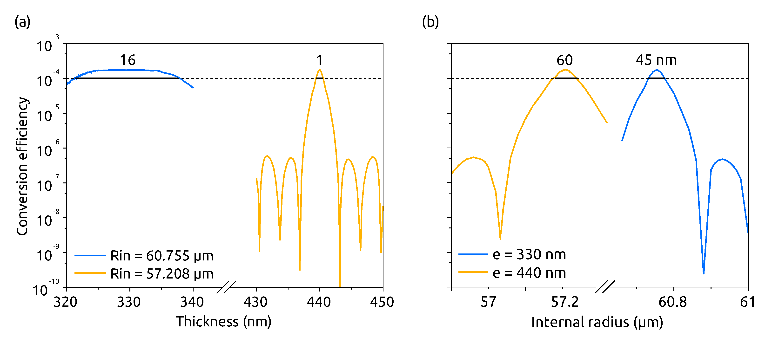
In order to illustrate the interest of the robust geometry presented before, we have computed the conversion efficiency for a silicon microring ( m f = 400 ) for two different internal radii: (i) R i n = 60.755 μ m which corresponds to the robust geometry determined from Figure 5, and (ii) R i n = 57.208 μ m which corresponds to the SHG point for e = 440 nm. To simulate a fabrication error, the thickness is swept around the nominal value, e = 330 nm in the first case and e = 440 nm in the second one. For each new thickness, the fundamental wavelength is adjusted around 2.3 μ m in order to keep the pump resonant and the fundamental mode at the azimuthal number m f = 400 . On the other side, the SH is not resonant (except for e = 330 nm or 440 nm); thus, a pseudo-azimuthal number m S H is interpolated between the closest resonant wavelengths in order to compute η . The results are shown in Figure 6a.
In both cases, η m a x 1.7 × 10 4 when the thickness has the optimum value, which yields the optimum microring radius. For the robust geometry (blue line), the SHG remains efficiently, even when the thickness differs by 10 nm from the optimum value, whereas for the other geometry (orange line), η decreases by at least two orders of magnitude when the thickness differs from the optimum value. In the first case, η is larger than 10 4 on a thickness range spanning more than 15 nm, while the range is as narrow as 1 nm in the second case. This result confirms what was found in the previous section: the R i n = f ( e ) plots allow one to find geometries which can accommodate fabrication errors. Our result is different from what was observed by [23] for GaAs, since here we used resonant conditions while neither the fundamental nor the SH modes were resonant in the other article.
Figure 6b shows the same kind of study when the internal radius is swept while the thickness is fixed to (i) e = 330 nm in the case of the robust geometry and (ii) e = 440 nm in the other case. We can see that a fabrication deviation of the radius is not as critical as the one for the thickness, since in both cases at least a 45 nm-deviation on R i n is allowed to keep the conversion efficiency larger than 10 4 .
Finally, we performed the same optimization for the most promising geometry for SHG, i.e., for small radii (Figure 3a), and with m f = 100 to use λ f > 2.2 μ m (Figure 2a). The robust geometry corresponds to e = 320 nm, R i n = 14.275 μ m and leads to η 10 3 for P i n = 1 mW which is only one order of magnitude smaller than what is theoretically expected in GaAs [23], for instance.

5. Conclusions

In this work, we have theoretically studied Si microrings with an effective second-order susceptibility. We have determined the geometries and the near-infrared pump wavelengths to have a large SHG efficiency where a quasi-phase matching condition is assured thanks to the 4-bar symmetry. In particular, we have concentrated our attention on the effects of uncontrolled fabrication variations. Our comprehensive study shows that it is possible to find microring geometries where the SHG efficiency is almost independent of fabrication errors. This allows relaxing the fabrication tolerances and the use of post-fabrication thermal trimming of the microring resonances. Finally, since these particular geometries rely on the knowledge of the dependence of the mode confinement on the specific geometry and not on the material itself, the method can be extended to other material systems than Si, provided they should show 4-bar symmetry.

Author Contributions

Conceptualization, P.G., C.V., and L.P.; modeling, P.G., C.V., C.C., S.S., and M.P.; refractive index measurements, M.G. and M.B.; writing—original draft, P.G. and C.V.; writing—review and editing, all; supervision, L.P. All authors have read and agreed to the published version of the manuscript.

Funding

This work is supported by the NEMO project (PRIN 2015KEZNYM).

Acknowledgments

The authors want to thank all the past members of the Nanoscience Laboratory of the University of Trento group for the stimulating discussions, and the CNR Naples group, in particular Iolanda Ricciardi and Maurizio de Rosa, for the fruitful and useful collaboration.

Conflicts of Interest

The authors declare no conflict of interest. The funders had no role in the design of the study; in the collection, analyses, or interpretation of data; in the writing of the manuscript, or in the decision to publish the results.

Appendix A. Refractive Indexes

The refractive index dispersions result from a Sellmeier fit of ellipsometry measurements performed at the Fondazione Bruno Kessler where the microring resonators are fabricated. The wavelength is expressed in μ m.
  • for Si
    n 2 1 = 10.651616 × λ 2 / ( λ 2 0.0913386 )
  • for SiO 2
    n 2 1 = 459.19197 × λ 2 / ( λ 2 0.00547762 ) 458.11172 × λ 2 / λ 2
  • for Si 3 N 4
    n 2 1 = 8.8624299 × λ 2 / ( λ 2 0.08495882 ) 5.9856771 × λ 2 / λ 2

Appendix B. Phase Matching Condition

With the assumption χ z x y ( 2 ) 0 , the SHG arises from the coupling of the x and y-components of the fundamental mode with the z-component of the SH mode according to:
E z S H = χ z x y ( 2 ) E x f E y f
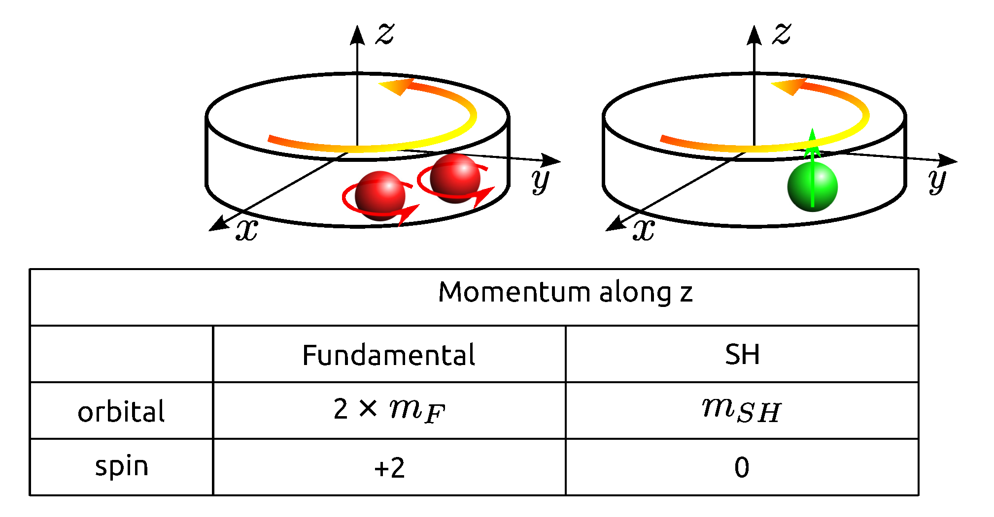
The Cartesian coordinates are not adapted to the cylindrical symmetry of the system; thus, it is useful to use the circular polarizations instead. A x-linearly polarized photon state can be written as a linear combination of two circularly polarized photon states: | x = A ( | + + | ) . For a y-polarization: | y = B ( | + | ) , where A and B are normalization constants. Hence, the two-photon state | x y used to generate the SH can be rewritten as: | x y = B ( | + + | ) . This means that the SHG uses either two photons | + or two photons | . In the following, we study the case where two | + photons interact. The angular momentum conservation, illustrated in Figure A1, leads to the phase-matching condition: m S H = 2 m f + 2 .
Figure A1. Illustration of the angular momentum given in . Two fundamental photons (red), circularly polarized, are converted into one SH photon (green) linearly polarized.
Applsci 10 09047 g0a1
yes

References

  1. Diddams, S.A.; Jones, D.J.; Ye, J.; Cundiff, S.T.; Hall, J.L.; Ranka, J.K.; Windeler, R.S.; Holzwarth, R.; Udem, T.; Hänsch, T.W. Direct Link between Microwave and Optical Frequencies with a 300 THz Femtosecond Laser Comb. Phys. Rev. Lett. 2000, 84, 5102–5105. [Google Scholar] [CrossRef] [PubMed] [Green Version]
  2. Griffith, A.G.; Lau, R.K.; Cardenas, J.; Okawachi, Y.; Mohanty, A.; Fain, R.; Lee, Y.H.D.; Yu, M.; Phare, C.T.; Poitras, C.B.; et al. Silicon-chip mid-infrared frequency comb generation. Nat. Commun. 2015, 6, 6299. [Google Scholar] [CrossRef] [PubMed]
  3. Diddams, S.A.; Ma, L.S.; Ye, J.; Hall, J.L. Broadband optical frequency comb generation with a phase-modulated parametric oscillator. Opt. Lett. 1999, 24, 1747. [Google Scholar] [CrossRef] [PubMed] [Green Version]
  4. Leo, F.; Hansson, T.; Ricciardi, I.; De Rosa, M.; Coen, S.; Wabnitz, S.; Erkintalo, M. Frequency-comb formation in doubly resonant second-harmonic generation. Phys. Rev. A 2016, 93. [Google Scholar] [CrossRef] [Green Version]
  5. Leo, F.; Hansson, T.; Ricciardi, I.; De Rosa, M.; Coen, S.; Wabnitz, S.; Erkintalo, M. Walk-Off-Induced Modulation Instability, Temporal Pattern Formation, and Frequency Comb Generation in Cavity-Enhanced Second-Harmonic Generation. Phys. Rev. Lett. 2016, 116. [Google Scholar] [CrossRef]
  6. Ricciardi, I.; Mosca, S.; Parisi, M.; Maddaloni, P.; Santamaria, L.; De Natale, P.; De Rosa, M. Frequency comb generation in quadratic nonlinear media. Phys. Rev. A 2015, 91. [Google Scholar] [CrossRef] [Green Version]
  7. Mosca, S.; Parisi, M.; Ricciardi, I.; Leo, F.; Hansson, T.; Erkintalo, M.; Maddaloni, P.; De Natale, P.; Wabnitz, S.; De Rosa, M. Modulation Instability Induced Frequency Comb Generation in a Continuously Pumped Optical Parametric Oscillator. Phys. Rev. Lett. 2018, 121. [Google Scholar] [CrossRef] [Green Version]
  8. Ilchenko, V.S.; Savchenkov, A.A.; Matsko, A.B.; Maleki, L. Nonlinear Optics and Crystalline Whispering Gallery Mode Cavities. Phys. Rev. Lett. 2004, 92. [Google Scholar] [CrossRef]
  9. Wang, C.; Burek, M.J.; Lin, Z.; Atikian, H.A.; Venkataraman, V.; Huang, I.C.; Stark, P.; Lončar, M. Integrated high quality factor lithium niobate microdisk resonators. Opt. Express 2014, 22, 30924. [Google Scholar] [CrossRef]
  10. Guo, X.; Zou, C.L.; Tang, H.X. Second-harmonic generation in aluminum nitride microrings with 2500%/W conversion efficiency. Optica 2016, 3, 1126. [Google Scholar] [CrossRef]
  11. Roland, I.; Gromovyi, M.; Zeng, Y.; El Kurdi, M.; Sauvage, S.; Brimont, C.; Guillet, T.; Gayral, B.; Semond, F.; Duboz, J.Y.; et al. Phase-matched second harmonic generation with on-chip GaN-on-Si microdisks. Sci. Rep. 2016, 6, 34191. [Google Scholar] [CrossRef] [PubMed] [Green Version]
  12. Mariani, S.; Andronico, A.; Lemaître, A.; Favero, I.; Ducci, S.; Leo, G. Second-harmonic generation in AlGaAs microdisks in the telecom range. Opt. Lett. 2014, 39, 3062. [Google Scholar] [CrossRef] [PubMed]
  13. Kuo, P.S.; Bravo-Abad, J.; Solomon, G.S. Second-harmonic generation using -quasi-phasematching in a GaAs whispering-gallery-mode microcavity. Nat. Commun. 2014, 5. [Google Scholar] [CrossRef] [PubMed] [Green Version]
  14. Lake, D.P.; Mitchell, M.; Jayakumar, H.; dos Santos, L.F.; Curic, D.; Barclay, P.E. Efficient telecom to visible wavelength conversion in doubly resonant gallium phosphide microdisks. Appl. Phys. Lett. 2016, 108, 031109. [Google Scholar] [CrossRef]
  15. Vivien, L.; Pavesi, L. (Eds.) Handbook of Silicon Photonics; Series in Optics And Optoelectronics; OCLC: 914966931; CRC Press: Boca Raton, FL, USA, 2013. [Google Scholar]
  16. Borghi, M.; Castellan, C.; Signorini, S.; Trenti, A.; Pavesi, L. Nonlinear silicon photonics. J. Opt. 2017, 19, 093002. [Google Scholar] [CrossRef]
  17. Cazzanelli, M.; Bianco, F.; Borga, E.; Pucker, G.; Ghulinyan, M.; Degoli, E.; Luppi, E.; Véniard, V.; Ossicini, S.; Modotto, D.; et al. Second-harmonic generation in silicon waveguides strained by silicon nitride. Nat. Mater. 2011, 11, 148–154. [Google Scholar] [CrossRef]
  18. Castellan, C.; Trenti, A.; Vecchi, C.; Marchesini, A.; Mancinelli, M.; Ghulinyan, M.; Pucker, G.; Pavesi, L. On the origin of second harmonic generation in silicon waveguides with silicon nitride cladding. Sci. Rep. 2018. submitted. [Google Scholar] [CrossRef] [Green Version]
  19. Levy, J.S.; Foster, M.A.; Gaeta, A.L.; Lipson, M. Harmonic generation in silicon nitride ring resonators. Opt. Express 2011, 19, 11415. [Google Scholar] [CrossRef] [Green Version]
  20. Timurdogan, E.; Poulton, C.V.; Byrd, M.J.; Watts, M.R. Electric field-induced second-order nonlinear optical effects in silicon waveguides. Nat. Photonics 2017, 11, 200–206. [Google Scholar] [CrossRef] [Green Version]
  21. Franchi, R.; Castellan, C.; Ghulinyan, M.; Pavesi, L. Second-harmonic generation in periodically poled silicon waveguides with lateral pin junctions: Publisher’s note. Opt. Lett. 2020, 45, 3348. [Google Scholar] [CrossRef]
  22. Berciano, M.; Marcaud, G.; Damas, P.; Le Roux, X.; Crozat, P.; Alonso Ramos, C.; Pérez Galacho, D.; Benedikovic, D.; Marris-Morini, D.; Cassan, E.; et al. Fast linear electro-optic effect in a centrosymmetric semiconductor. Commun. Phys. 2018, 1, 64. [Google Scholar] [CrossRef]
  23. Kuo, P.S.; Solomon, G.S. On- and off-resonance second-harmonic generation in GaAs microdisks. Opt. Express 2011, 19, 16898–16918. [Google Scholar] [CrossRef] [PubMed]
  24. Snyder, A.W.; Love, J.D. Optical Waveguide Theory; Number 190 in Science Paperbacks; Chapman and Hall: London, UK; New York, NY, USA, 1983. [Google Scholar]
  25. Manganelli, C.L.; Pintus, P.; Bonati, C. Modeling of strain-induced Pockels effect in Silicon. Opt. Express 2015, 23, 28649–28666. [Google Scholar] [CrossRef] [PubMed] [Green Version]
  26. Olivares, I.; Parra, J.; Brimont, A.; Sanchis, P. Enhancing Pockels effect in strained silicon waveguides. Opt. Express 2019, 27, 26882–26892. [Google Scholar] [CrossRef]
  27. Lafforgue, C.; Berciano, M.; Deniel, L.; Marcaud, G.; Le Roux, X.; Alonso-Ramos, C.; Benedikovic, D.; Vakarin, V.; Ruiz-Caridad, A.; Crozat, P.; et al. Strain induced Pockels effect in silicon for electro-optic modulation. In Proceedings of the Silicon Photonics XV, International Society for Optics and Photonics, San Francisco, CA, USA, 3–6 February 2020; Volume 11285, p. 112850D. [Google Scholar]
  28. Dumeige, Y.; Féron, P. Whispering-gallery-mode analysis of phase-matched doubly resonant second-harmonic generation. Phys. Rev. A 2006, 74, 063804. [Google Scholar] [CrossRef] [Green Version]
  29. COMSOL AB, Stokholm Sweden. COMSOL Multiphysics v 5.3©. Available online: http://www.comsol.com (accessed on 15 September 2017).
  30. Bristow, A.D.; Rotenberg, N.; van Driel, H.M. Two-photon absorption and Kerr coefficients of silicon for 850–2200 nm. Appl. Phys. Lett. 2007, 90, 191104. [Google Scholar] [CrossRef]
  31. Yariv, A.; Yeh, P. Electromagnetic propagation in periodic stratified media II Birefringence, phase matching, and X-ray lasers. J. Opt. Soc. Am. 1977, 67, 438. [Google Scholar] [CrossRef]
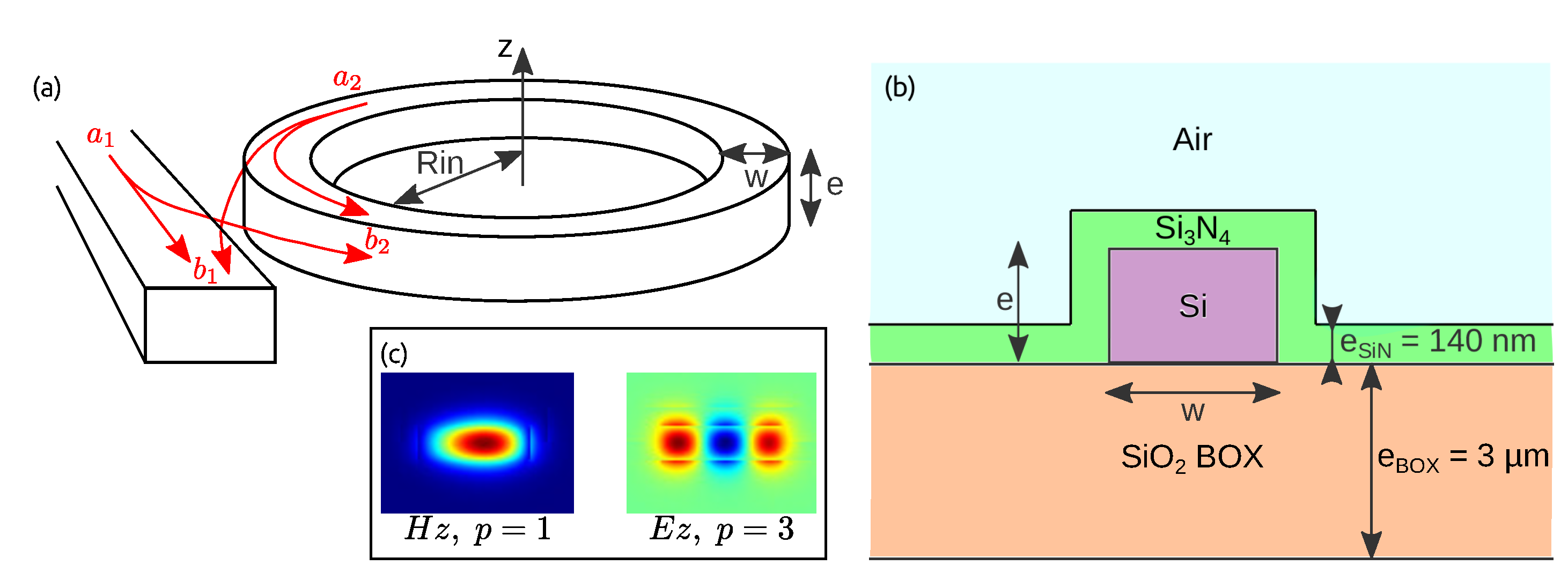
Figure 1. (a) System and notation used for the SHG study. (b) Cross section of the microring showing the materials and thicknesses. (c) Mode profiles of a TE mode with radial number p = 1 and TM mode with radial number p = 3 .
Applsci 10 09047 g001
Figure 2. Fundamental wavelengths and geometries fulfilling the requirements for the SHG in a Si microring cladded by Si 3 N 4 for p f = 1 , p S H = 3 , a Hz fundamental mode, and a Ez SH mode. (a) For a fixed thickness e = 280 nm and three different widths w. The points correspond to different fundamental azimuthal numbers m f . (b) For a fixed width w = 800 nm and different thicknesses represented by the different colored points. The three curves correspond to different m f values.
Applsci 10 09047 g002
Figure 3. SHG conversion efficiency in Si microring cladded by Si 3 N 4 . The pump power is P i n = 1 mW, χ z x y ( 2 ) = 1 pm/V, and the intrinsic and coupling Q-factors are 10 4 . (a) Varying the internal radius R i n , for a fixed thickness e = 280 nm and different widths w. (b) Varying the thickness e, for a fixed width w = 800 nm and a fixed internal radius ( R i n 60 μ m) or a fixed fundamental azimuthal number ( m f = 400 ) and different radii.
Applsci 10 09047 g003
Figure 4. Resonant wavelengths for modes ( m = 400 , H z polarization, p = 1 ) around 2.3 μ m (labeled as F) and ( m = 802 , E z polarization, p = 3 ) around 1.15 μ m (labeled as SH) in a Si microring of width w = 800 nm cladded by S i 3 N 4 with respect to (a) the thickness e and (b) the internal radius R i n . Please note that the notations F and SH are chosen for the sake of simplicity but really correspond to fundamental and SH only at the crossing points. The colors are the same as in Figure 2b to make the correspondence easy, and an example of correspondence is given with points A and B.
Applsci 10 09047 g004
Figure 5. Internal radii values that fulfill the criteria of SHG with high efficiency as a function of the waveguide thickness. We assumed a silicon microring of width w = 800 nm and a fundamental azimuthal number m f = 400 . The colors are the same as Figure 2b to ease the comparison between the two plots.
Applsci 10 09047 g005
Figure 6. SHG conversion efficiency as functions of thickness e (a) and internal radius R i n (b). The blue line corresponds to the maximum of Figure 5 where the highest efficiency was obtained for R i n = 60.755 μ m and e = 330 nm. The orange line corresponds to the point R i n = 57.208 μ m and e = 440 nm. The vertical axis is the same in both cases. The waveguide width is w = 800 nm and the pump power P i n = 1 mW. The black lines indicate the ranges for which η 10 4 . In (a) η 10 4 in a range of only 1 nm for the yellow line, and in a range of 16 nm for the blue one, showing a robustness against fabrication defects of this geometry. In (b) η 10 4 in a range larger than 40 nm for both the geometries, showing that the conversion efficiency is not affected in a critical way by variations in the internal radius of the ring.
Applsci 10 09047 g006
Publisher’s Note: MDPI stays neutral with regard to jurisdictional claims in published maps and institutional affiliations.