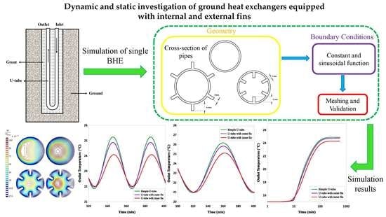
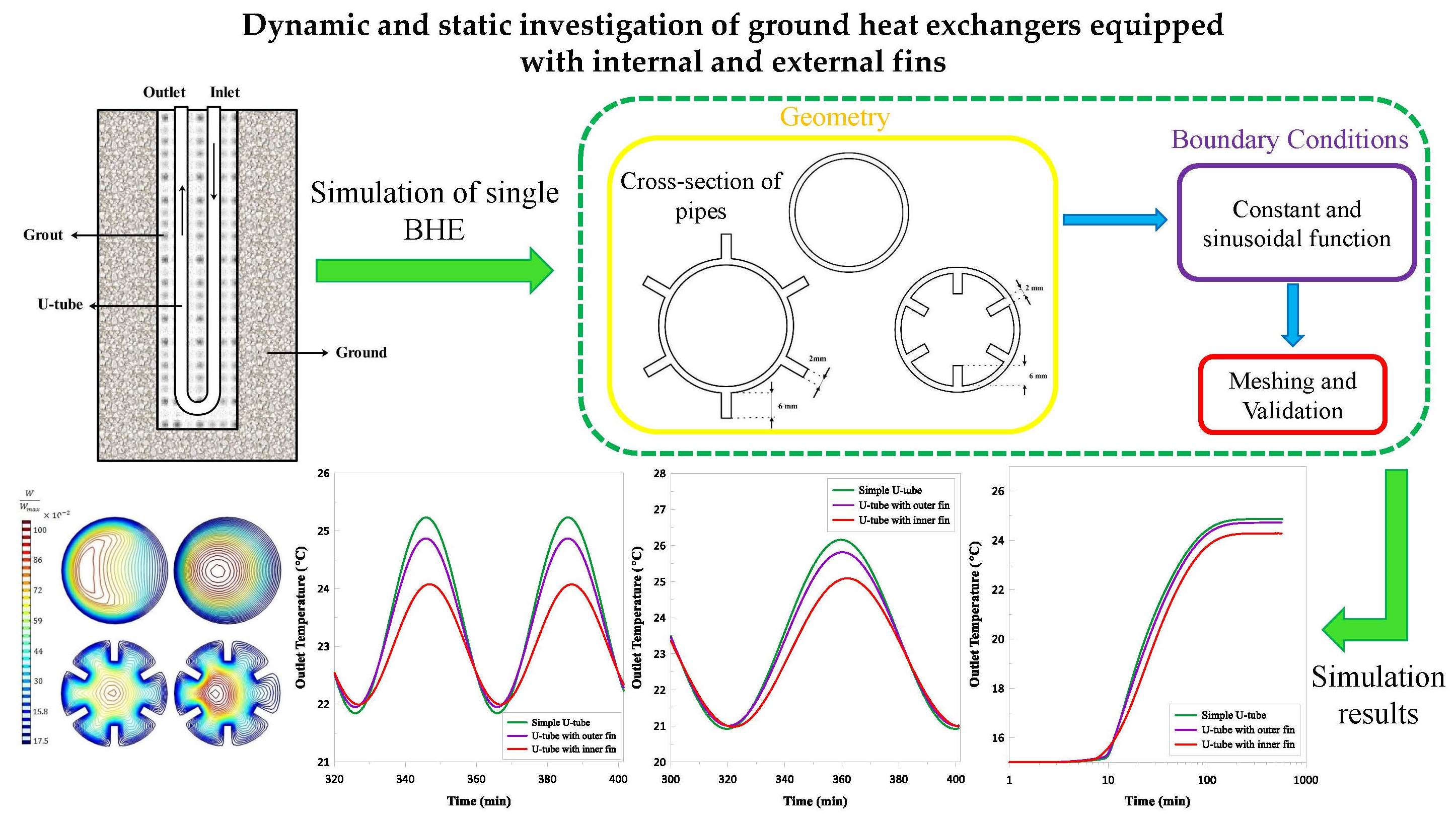
Dynamic and Static Investigation of Ground Heat Exchangers Equipped with Internal and External Fins


Abstract
1. Introduction
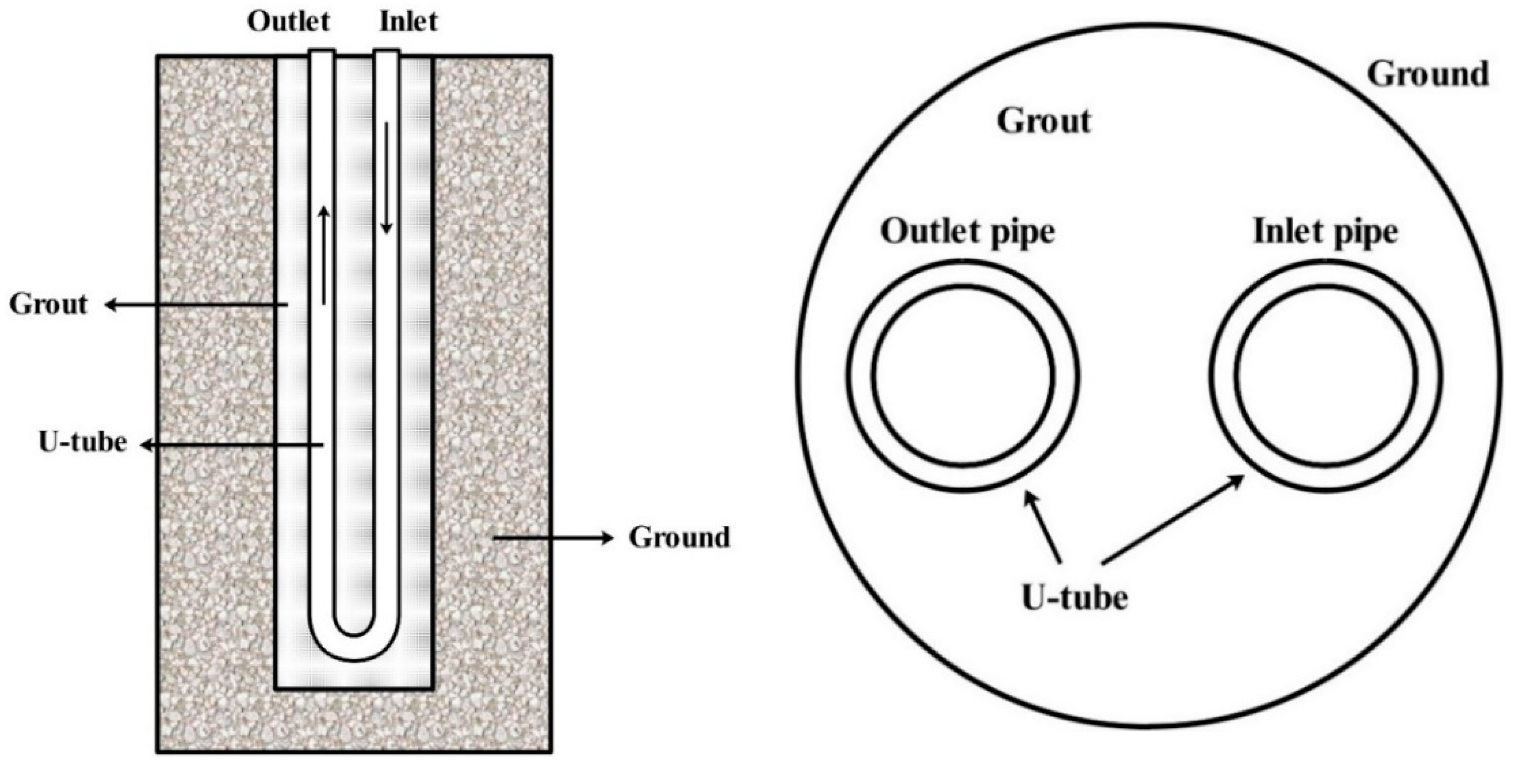
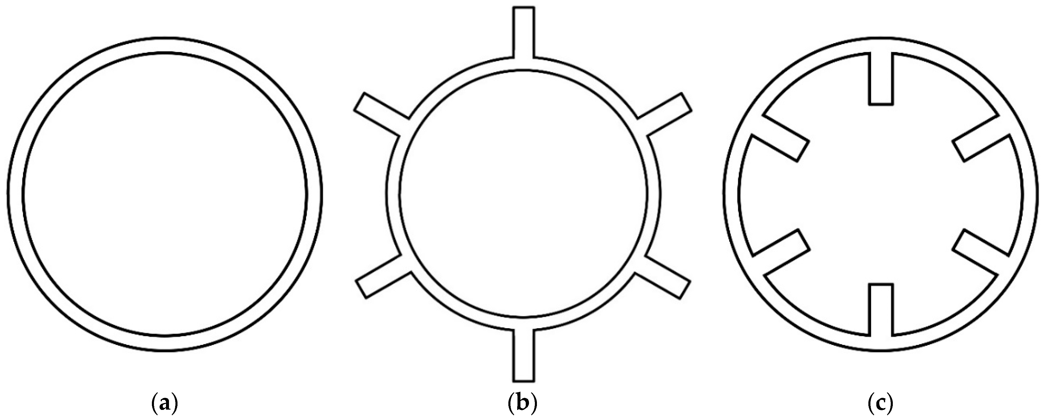
2. Case Study
3. Numerical Setup
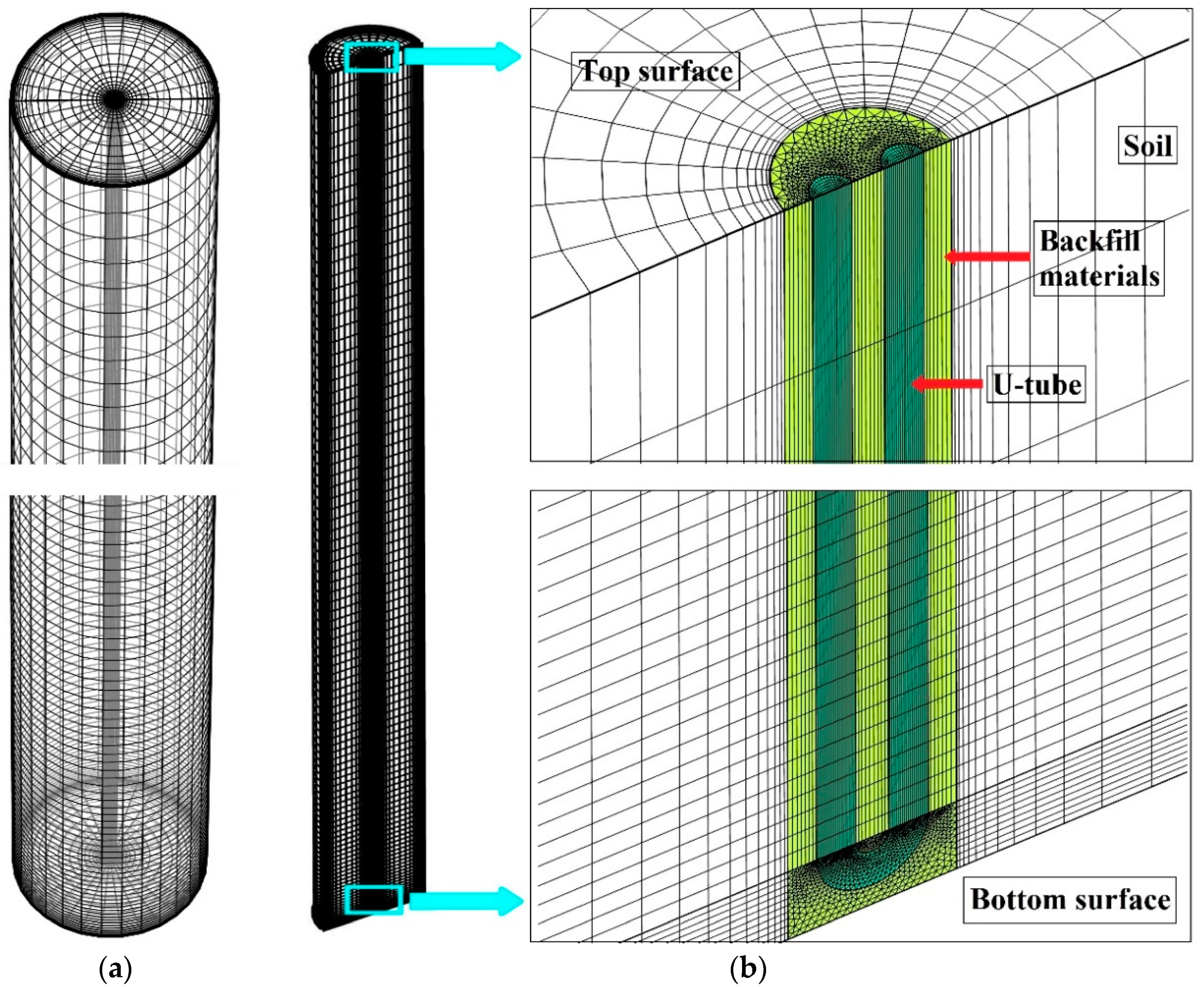
3.1. Mesh Generation
3.2. Solver
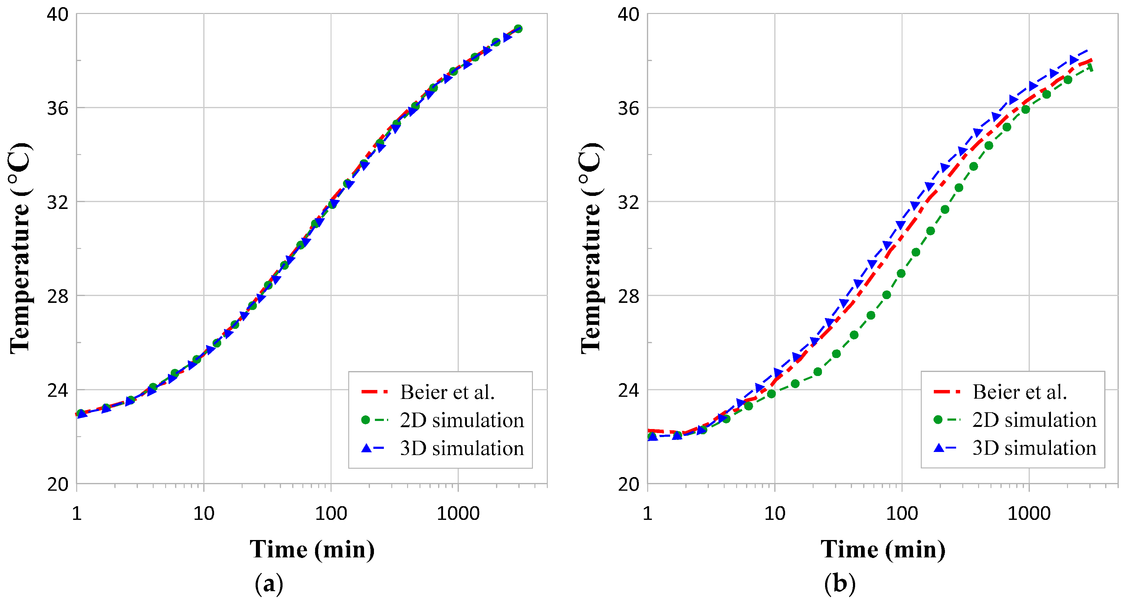
4. Validation
5. Results and Discussions
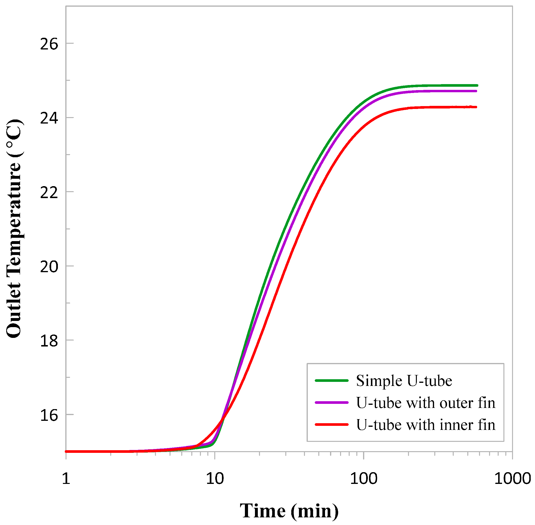
5.1. Long Timescale Response
5.2. Short Timescale Response
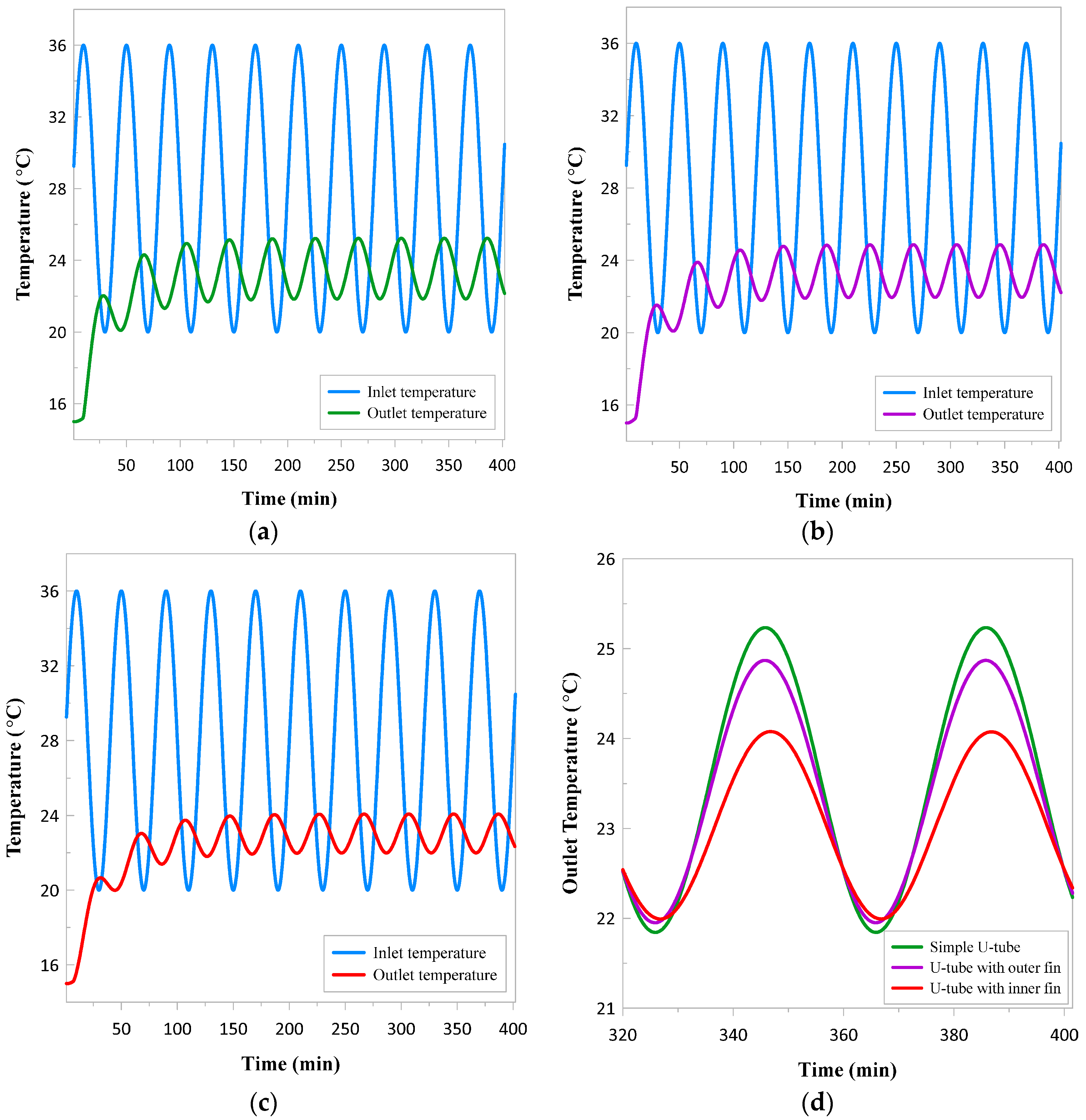
Frequency Response Test
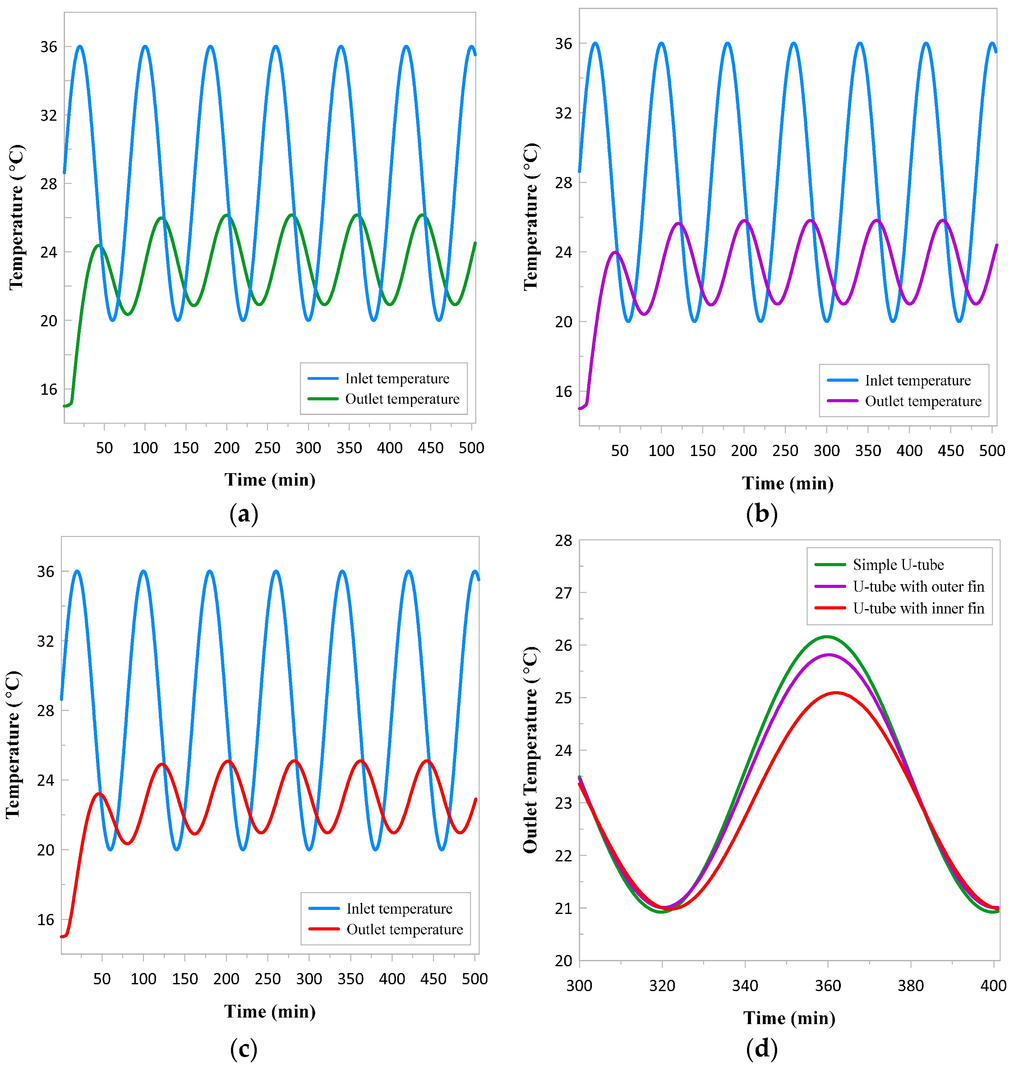
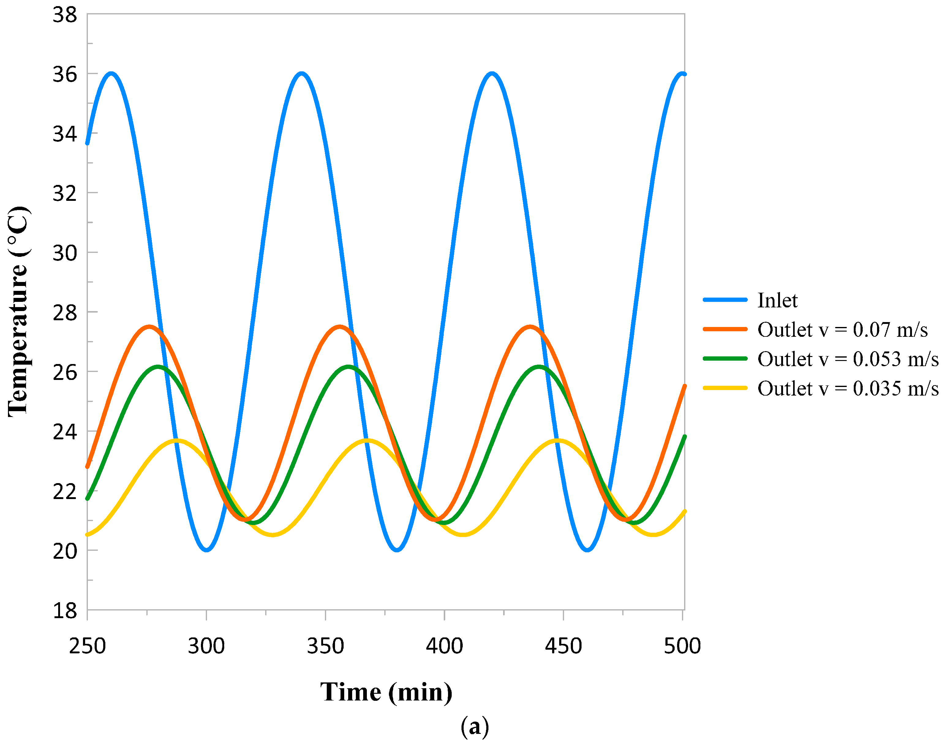
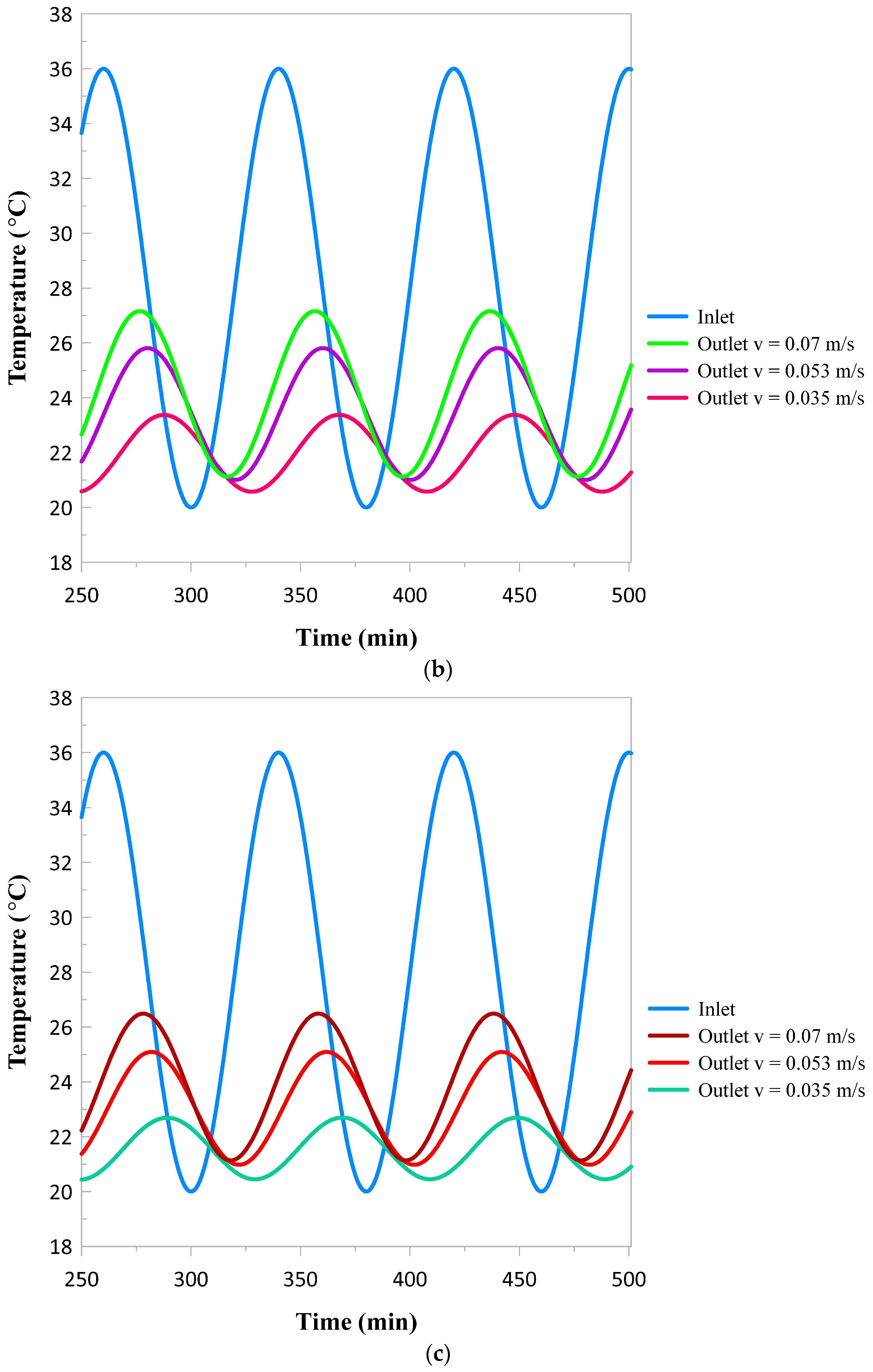
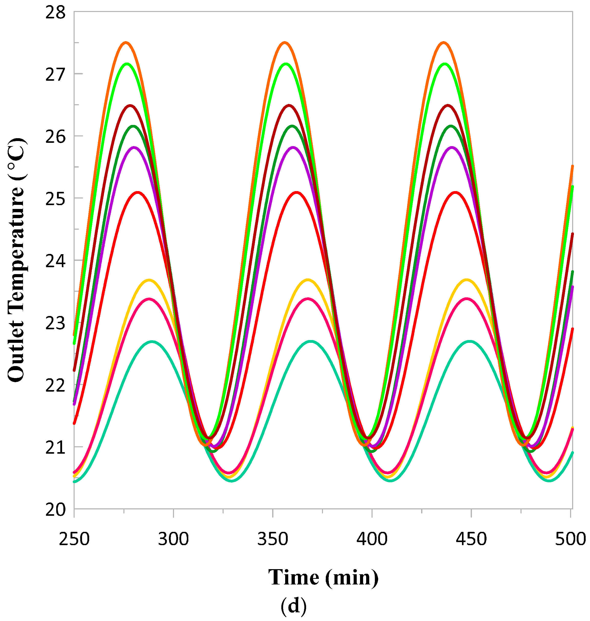
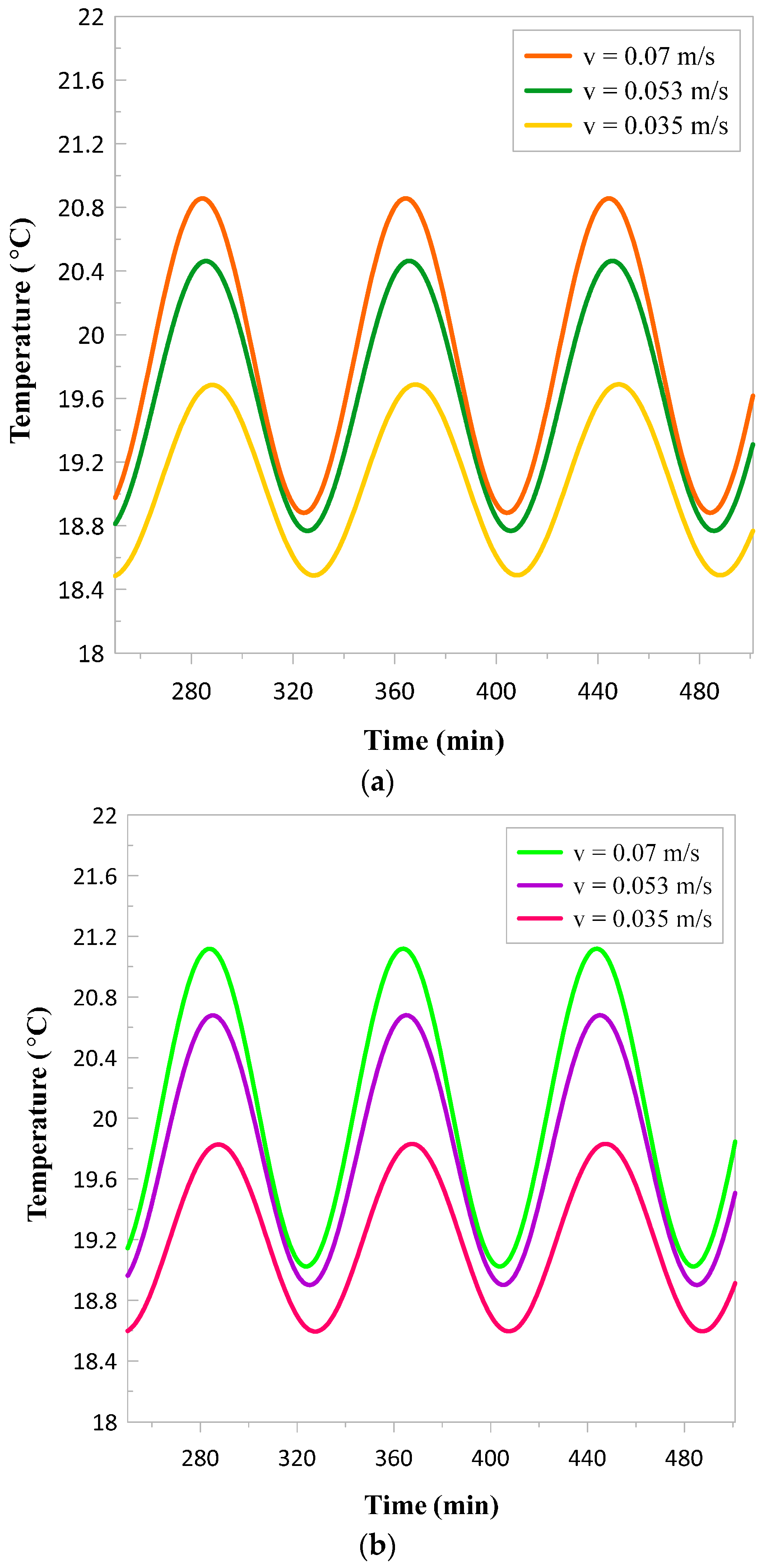
5.3. Fluid Velocity Effects with Sinusoidal Inlet Temperature
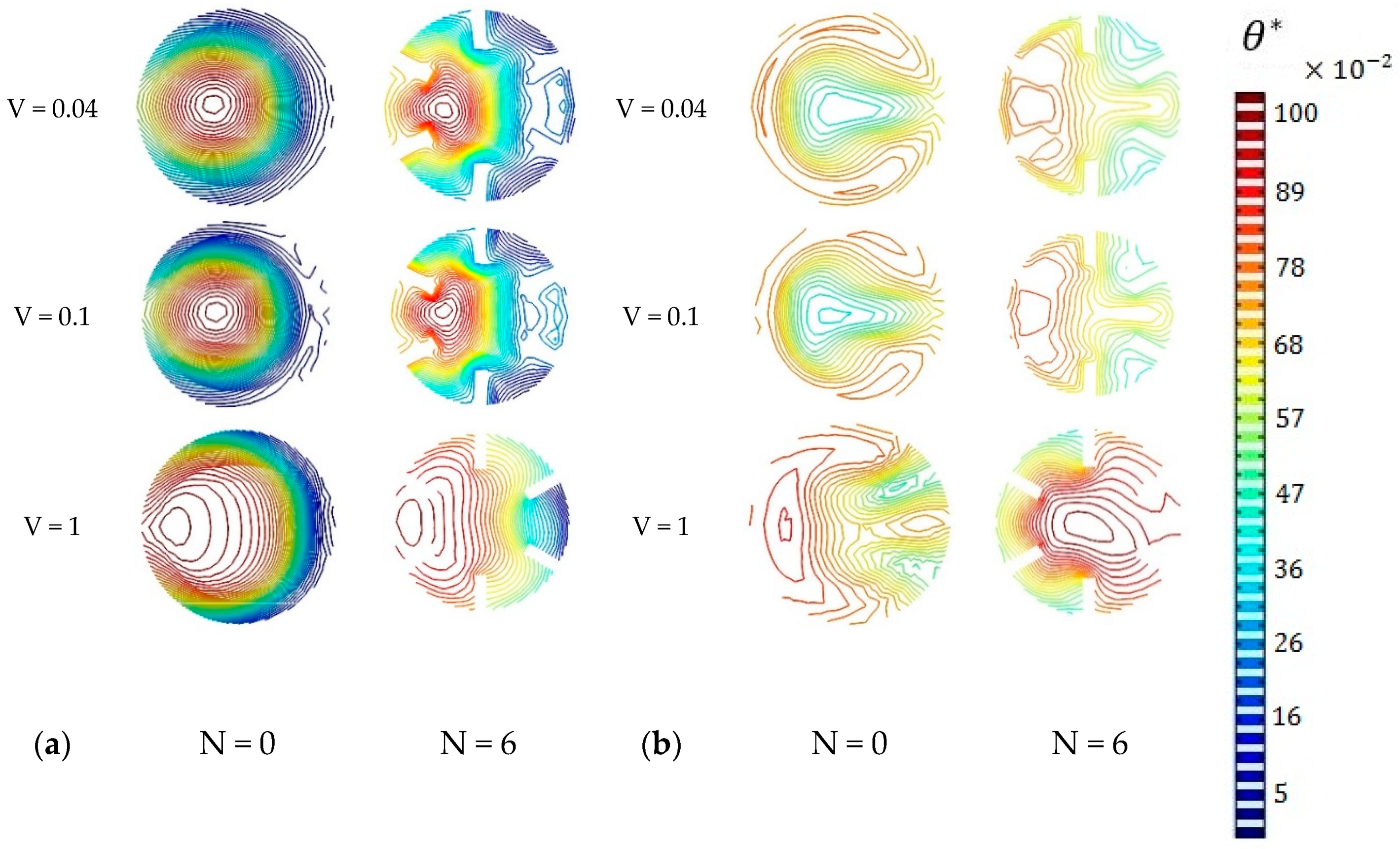
5.4. Axial Velocity and Temperature Contours
6. Conclusions
Author Contributions
Funding
Conflicts of Interest
References
- Zeng, H.; Diao, N.; Fang, Z. Heat transfer analysis of boreholes in vertical ground heat exchangers. Int. J. Heat Mass Transf. 2003, 46, 4467–4481. [Google Scholar] [CrossRef]
- Soltani, M.; Kashkooli, F.M.; Dehghani-Sanij, A.; Kazemi, A.R.; Bordbar, N.; Farshchi, M.J.; Elmi, M.; Gharali, K.; Dusseault, M.B. A comprehensive study of geothermal heating and cooling systems. Sustain. Cities Soc. 2019, 44, 793–818. [Google Scholar] [CrossRef]
- Kharseh, M.; Al-Khawaja, M.; Suleiman, M.T. Potential of ground source heat pump systems in cooling-dominated environments: Residential buildings. Geothermics 2015, 57, 104–110. [Google Scholar] [CrossRef]
- Salem, A.; Hashim, H. Feasibility of Geothermal Cooling in Middle East. In Latest Trends in Sustainable and Green Development, Proceedings of the 3rd International Conference on Urban Sustainability, Cultural Sustainability, Green Development, Green Structures and Clean Cars (USCUDAR’12), Barcelona, Spain, 17–19 October 2012; Zahran, M., Ed.; WSEAS Press: Athens, Greece, 2012; pp. 105–112. ISBN 978-1-61804-132-6. [Google Scholar]
- Biglarian, H.; Abbaspour, M.; Saidi, M.H. Evaluation of a transient borehole heat exchanger model in dynamic simulation of a ground source heat pump system. Energy 2018, 147, 81–93. [Google Scholar] [CrossRef]
- Angelotti, A.; Alberti, L.; La Licata, I.; Antelmi, M. Energy performance and thermal impact of a Borehole Heat Exchanger in a sandy aquifer: Influence of the groundwater velocity. Energy Convers. Manag. 2014, 77, 700–708. [Google Scholar] [CrossRef]
- Beier, R.A.; Acuña, J.; Mogensen, P.; Palm, B. Transient heat transfer in a coaxial borehole heat exchanger. Geothermics 2014, 51, 470–482. [Google Scholar] [CrossRef]
- Keshavarzzadeh, A.H.; Zanjani, A.M.; Gharali, K.; Dusseault, M.B. Multi-objective evolutionary-based optimization of a ground source heat exchanger geometry using various optimization techniques. Geothermics 2020, 86, 101861. [Google Scholar] [CrossRef]
- Hellström, G. Ground Heat Storage: Thermal Analyses of Duct Storage Systems. Ph.D. Thesis, University of Lund, Lund, Sweden, 1991. [Google Scholar]
- Zhang, L.; Zhang, Q.; Huang, G.; Du, Y. A p(t)-linear average method to estimate the thermal parameters of the borehole heat exchangers for in situ thermal response test. Appl. Energy 2014, 131, 211–221. [Google Scholar] [CrossRef]
- Zhang, L.; Zhang, Q.; Acuña, J.; Ma, X. Improved p(t)-linear Average Method for Ground Thermal Properties Estimation during in-situ Thermal Response Test. Procedia Eng. 2015, 121, 726–734. [Google Scholar] [CrossRef]
- Beier, R.A.; Spitler, J.D. Weighted average of inlet and outlet temperatures in borehole heat exchangers. Appl. Energy 2016, 174, 118–129. [Google Scholar] [CrossRef]
- Marcotte, D.; Pasquier, P. On the estimation of thermal resistance in borehole thermal conductivity test. Renew. Energy 2008, 33, 2407–2415. [Google Scholar] [CrossRef]
- Beier, R.A.; Acuña, J.; Mogensen, P.; Palm, B. Vertical temperature profiles and borehole resistance in a U-tube borehole heat exchanger. Geothermics 2012, 44, 23–32. [Google Scholar] [CrossRef]
- Sharqawy, M.H.; Mokheimer, E.M.; Badr, H.M. Effective pipe-to-borehole thermal resistance for vertical ground heat exchangers. Geothermics 2009, 38, 271–277. [Google Scholar] [CrossRef]
- Sliwa, T.; Rosen, M. Efficiency analysis of borehole heat exchangers as grout varies via thermal response test simulations. Geothermics 2017, 69, 132–138. [Google Scholar] [CrossRef]
- Borinaga-Treviño, R.; Pascual-Muñoz, P.; Castro-Fresno, D.; Blanco-Fernandez, E. Borehole thermal response and thermal resistance of four different grouting materials measured with a TRT. Appl. Therm. Eng. 2013, 53, 13–20. [Google Scholar] [CrossRef]
- Erol, S.; François, B. Efficiency of various grouting materials for borehole heat exchangers. Appl. Therm. Eng. 2014, 70, 788–799. [Google Scholar] [CrossRef]
- Eskilson, P. Thermal Analysis of Heat Extraction Boreholes. Ph.D. Thesis, University of Lund, Lund, Sweden, 1987. [Google Scholar]
- Beier, R.A. Transient heat transfer in a U-tube borehole heat exchanger. Appl. Therm. Eng. 2014, 62, 256–266. [Google Scholar] [CrossRef]
- Pu, L.; Qi, D.; Li, K.; Tan, H.; Li, Y. Simulation study on the thermal performance of vertical U-tube heat exchangers for ground source heat pump system. Appl. Therm. Eng. 2015, 79, 202–213. [Google Scholar] [CrossRef]
- Esen, H.; Inalli, M.; Esen, Y. Temperature distributions in boreholes of a vertical ground-coupled heat pump system. Renew. Energy 2009, 34, 2672–2679. [Google Scholar] [CrossRef]
- Li, Y.; An, Q.; Liu, L.; Zhao, J. Thermal Performance Investigation of Borehole Heat Exchanger with Different U-tube Diameter and Borehole Parameters. Energy Procedia 2014, 61, 2690–2694. [Google Scholar] [CrossRef]
- Zhu, L.; Chen, S.; Yang, Y.; Sun, Y. Transient heat transfer performance of a vertical double U-tube borehole heat exchanger under different operation conditions. Renew. Energy 2019, 131, 494–505. [Google Scholar] [CrossRef]
- Lee, C.K.; Lam, H.N. Computer simulation of borehole ground heat exchangers for geothermal heat pump systems. Renew. Energy 2008, 33, 1286–1296. [Google Scholar] [CrossRef]
- Yang, S.; Lee, S. Dynamic thermal analysis of a residential ground-source heat pump. Sustain. Energy Technol. Assess. 2020, 37, 100608. [Google Scholar] [CrossRef]
- Beckers, K.F.; Aguirre, G.A.; Tester, J.W. Hybrid ground-source heat pump systems for cooling-dominated applications: Experimental and numerical case-study of cooling for cellular tower shelters. Energy Build. 2018, 177, 341–350. [Google Scholar] [CrossRef]
- Nobari, M.R.H.; Gharali, K.; Tajdari, M. A Numerical Study of Flow and Heat Transfer in Internally Finned Rotating Curved Pipes. Numer. Heat Transfer Part A Appl. 2009, 56, 76–95. [Google Scholar] [CrossRef]
- Bouhacina, B.; Saim, R.; Oztop, H.F. Numerical investigation of a novel tube design for the geothermal borehole heat exchanger. Appl. Therm. Eng. 2015, 79, 153–162. [Google Scholar] [CrossRef]
- Saeidi, R.; Noorollahi, Y.; Esfahanian, V. Numerical simulation of a novel spiral type ground heat exchanger for enhancing heat transfer performance of geothermal heat pump. Energy Convers. Manag. 2018, 168, 296–307. [Google Scholar] [CrossRef]
- Patankar, S. Numerical Heat Transfer and Fluid Flow; Hemisphere Publishing: Washington, DC, USA; McGraw Hill: New York, NY, USA, 1980. [Google Scholar]
- Beier, R.A.; Smith, M.D.; Spitler, J.D. Reference data sets for vertical borehole ground heat exchanger models and thermal response test analysis. Geothermics 2011, 40, 79–85. [Google Scholar] [CrossRef]
- Rees, S.J.; He, M. A three-dimensional numerical model of borehole heat exchanger heat transfer and fluid flow. Geothermics 2013, 46, 1–13. [Google Scholar] [CrossRef]
- Noorollahi, Y.; Saeidi, R.; Mohammadi, M.; Amiri, A.; Hosseinzadeh, M. The effects of ground heat exchanger parameters changes on geothermal heat pump performance—A review. Appl. Therm. Eng. 2018, 129, 1645–1658. [Google Scholar] [CrossRef]
- Nobari, M.R.H.; Gharali, K. A numerical study of flow and heat transfer in internally finned rotating straight pipes and stationary curved pipes. Int. J. Heat Mass Transf. 2006, 49, 1185–1194. [Google Scholar] [CrossRef]


| Parameters | Value |
|---|---|
| Borehole diameter (mm) | 128 |
| Inner diameter of pipe (mm) | 30 |
| Outer diameter of pipe (mm) | 34 |
| Distance between centers of U-tube pipes (mm) | 55 |
| Borehole length (m) | 25 |
| Ground diameter (m) | 2 |
| Mesh 1 | Mesh 2 | Mesh 3 | |
|---|---|---|---|
| Elements number () | 174 | 330 | 500 |
| Fluid outlet temperature (°C) | 24.86 | 24.85 | 24.85 |
| Mesh 1 | Mesh 2 | Mesh 3 | ||
|---|---|---|---|---|
| U-tube with external fins | Element number () | 300 | 500 | 600 |
| Fluid outlet temperature (°C) | 24.64 | 24.71 | 24.72 | |
| U-tube with internal fins | Element number () | 300 | 420 | 600 |
| Fluid outlet temperature (°C) | 24.64 | 24.67 | 24.67 |
| Material | Density | Specific Heat Capacity | Thermal Conductivity |
|---|---|---|---|
| Fluid | 997 | 4148 | 0.6 |
| U-tube | 950 | 1500 | 0.44 |
| Grout | 1800 | 840 | 0.73 |
| Soil | 2200 | 2000 | 2.5 |
| Aluminum fin | 2700 | 904 | 237 |
| Parameters | Value |
|---|---|
| Borehole diameter (mm) | 126 |
| Inner diameter of pipe (mm) | 27.33 |
| Outer diameter of pipe (mm) | 33.40 |
| Distance between centers of U-tube pipes (mm) | 53 |
| Borehole length (m) | 18.3 |
| Pipe thermal conductivity | 0.39 |
| Grout thermal conductivity | 0.73 |
| Ground thermal conductivity | 2.82 |
| Average volumetric flow rate | 0.197 |
| Initial temperature of ground and grout (°C) | 22 |
| Velocity () | 0.06 | 0.04 | 0.02 | |
|---|---|---|---|---|
| Simple U-tube | Flow rate () | 0.042 | 0.028 | 0.014 |
| Reynolds number | 2049 | 1366 | 683 | |
| Outlet fluid temperature (°C) | 25.20 | 23.73 | 20.88 | |
| Borehole wall temperature (°C) | 20.46 | 19.93 | 18.72 | |
| U-tube with outer fins | Flow rate () | 0.042 | 0.028 | 0.014 |
| Reynolds number | 2049 | 1366 | 683 | |
| Outlet fluid temperature (°C) | 25.06 | 23.59 | 20.83 | |
| Borehole wall temperature (°C) | 20.67 | 20.08 | 18.78 | |
| U-tube with inner fins | Flow rate () | 0.038 | 0.025 | 0.013 |
| Reynolds number | 1945 | 1297 | 648 | |
| Outlet fluid temperature (°C) | 24.66 | 23.13 | 20.42 | |
| Borehole wall temperature (°C) | 20.50 | 19.89 | 18.55 | |
| Amplitude of Wave | Mean of Wave | ||
|---|---|---|---|
| Inlet Temperature | 8 | 28 | |
| Outlet temperature (°C) with a frequency of 1/4800 | Simple U-tube | 2.62 | 23.54 |
| U-tube with outer fins | 2.40 | 23.41 | |
| U-tube with inner fins | 2.06 | 23.03 | |
| Outlet temperature (°C) with a frequency of 1/2400 | Simple U-tube | 1.69 | 23.54 |
| U-tube with outer fins | 1.46 | 23.41 | |
| U-tube with inner fins | 1.04 | 23.03 | |
| Velocity () | Amplitude of Wave (°C) | Mean of Wave (°C) | ||
|---|---|---|---|---|
| 0.035 | 1.59 | 22.10 | 26.7% | |
| Simple U-tube | 0.053 | 2.62 | 23.54 | 19% |
| 0.070 | 3.24 | 24.26 | 15.4% | |
| 0.035 | 1.40 | 21.98 | 27.4% | |
| U-tube with outer fins | 0.053 | 2.40 | 23.41 | 19.6% |
| 0.070 | 3.00 | 24.14 | 16% | |
| 0.035 | 1.12 | 21.57 | 29.8% | |
| U-tube with inner fins | 0.053 | 2.06 | 23.03 | 21.5% |
| 0.070 | 2.68 | 23.81 | 17.6% |
| Velocity () | Amplitude of Wave (°C) | Mean of Wave (°C) | ||
|---|---|---|---|---|
| 0.035 | 0.59 | 19.09 | 27% | |
| Simple U-tube | 0.053 | 0.85 | 19.61 | 30.7% |
| 0.070 | 0.99 | 19.87 | 32% | |
| 0.035 | 0.62 | 19.21 | 28% | |
| U-tube with outer fins | 0.053 | 0.89 | 19.80 | 32% |
| 0.070 | 1.04 | 20.07 | 34% | |
| 0.035 | 0.56 | 19.04 | 26% | |
| U-tube with inner fins | 0.053 | 0.82 | 19.64 | 30.9% |
| 0.070 | 0.97 | 19.93 | 33% |
Publisher’s Note: MDPI stays neutral with regard to jurisdictional claims in published maps and institutional affiliations. |
© 2020 by the authors. Licensee MDPI, Basel, Switzerland. This article is an open access article distributed under the terms and conditions of the Creative Commons Attribution (CC BY) license (http://creativecommons.org/licenses/by/4.0/).
Share and Cite
Maleki Zanjani, A.; Gharali, K.; Al-Haq, A.; Nathwani, J. Dynamic and Static Investigation of Ground Heat Exchangers Equipped with Internal and External Fins. Appl. Sci. 2020, 10, 8689. https://doi.org/10.3390/app10238689
Maleki Zanjani A, Gharali K, Al-Haq A, Nathwani J. Dynamic and Static Investigation of Ground Heat Exchangers Equipped with Internal and External Fins. Applied Sciences. 2020; 10(23):8689. https://doi.org/10.3390/app10238689
Chicago/Turabian StyleMaleki Zanjani, Atefeh, Kobra Gharali, Armughan Al-Haq, and Jatin Nathwani. 2020. "Dynamic and Static Investigation of Ground Heat Exchangers Equipped with Internal and External Fins" Applied Sciences 10, no. 23: 8689. https://doi.org/10.3390/app10238689
APA StyleMaleki Zanjani, A., Gharali, K., Al-Haq, A., & Nathwani, J. (2020). Dynamic and Static Investigation of Ground Heat Exchangers Equipped with Internal and External Fins. Applied Sciences, 10(23), 8689. https://doi.org/10.3390/app10238689