Wideband Circularly Polarized Antenna Based on a Non-Uniform Metasurface


Abstract
1. Introduction
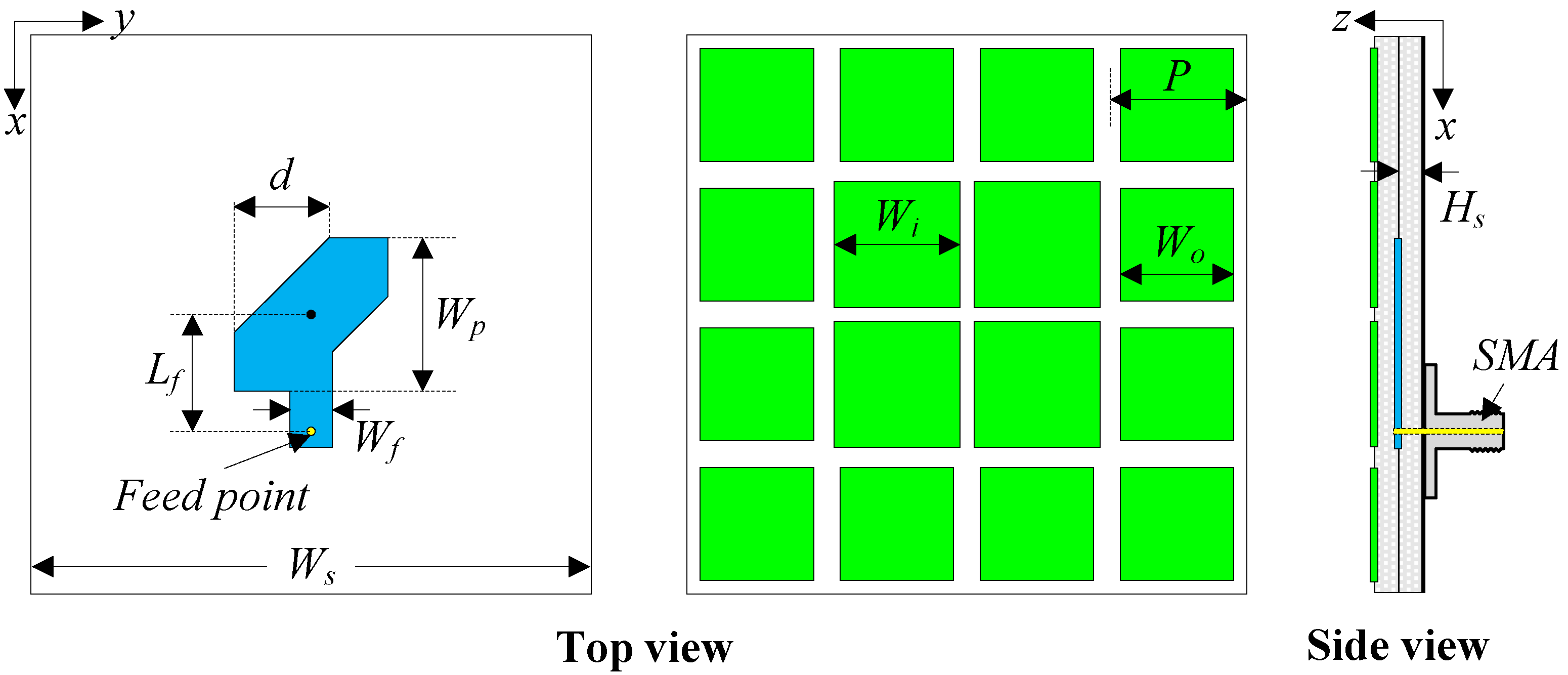
2. Antenna Geometry
3. Antenna Design
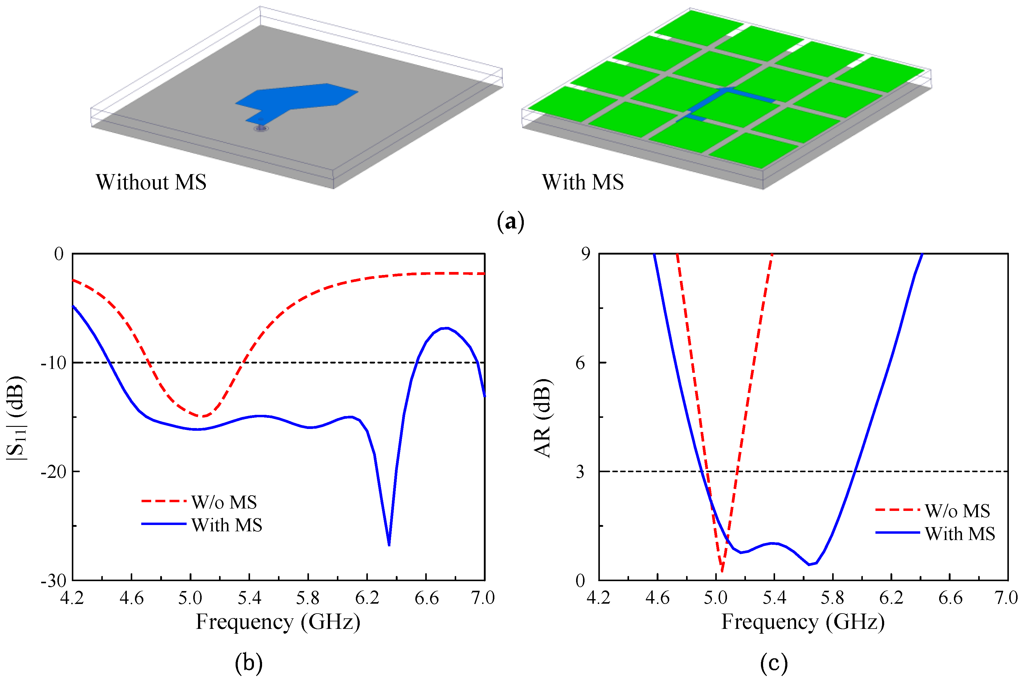
3.1. Antenna with Uniform MS
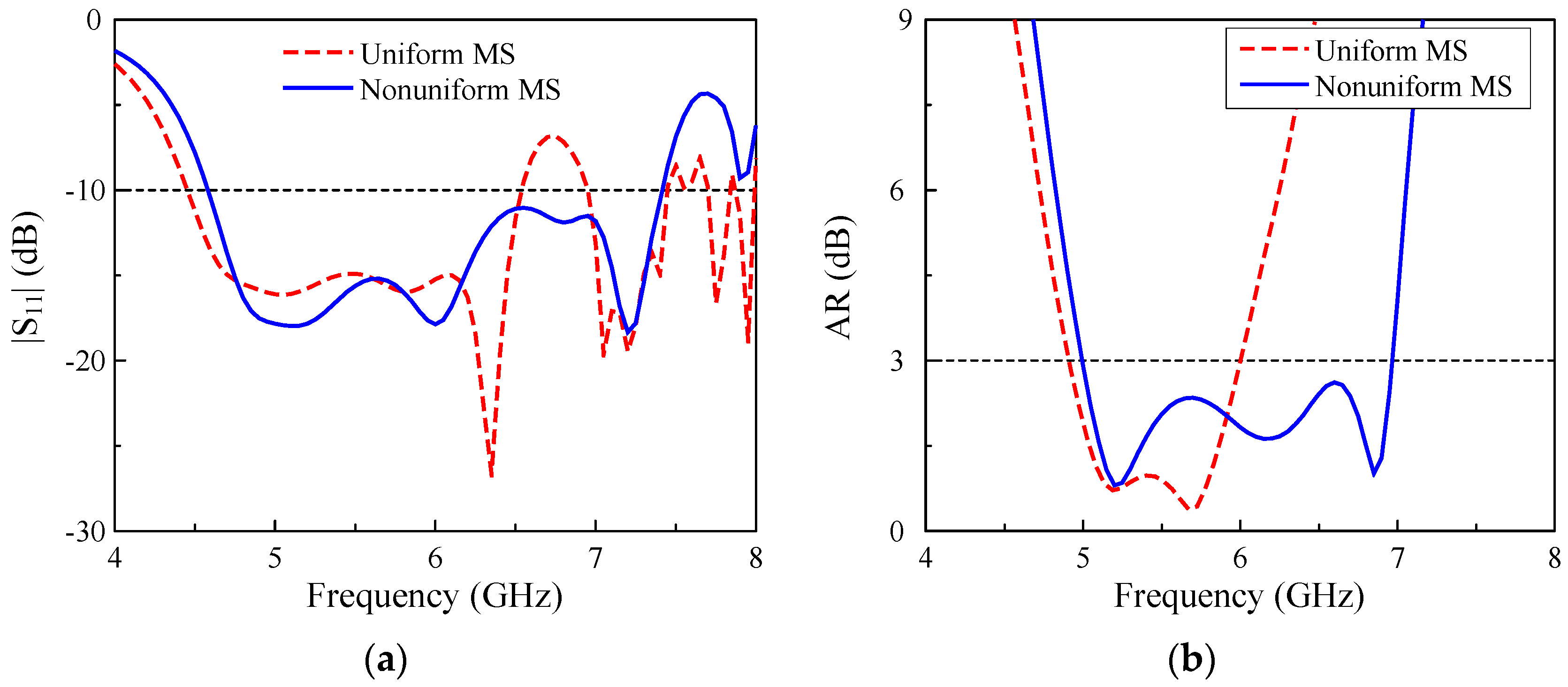
3.2. Antenna with Non-Uniform MS
3.3. Design Procedure
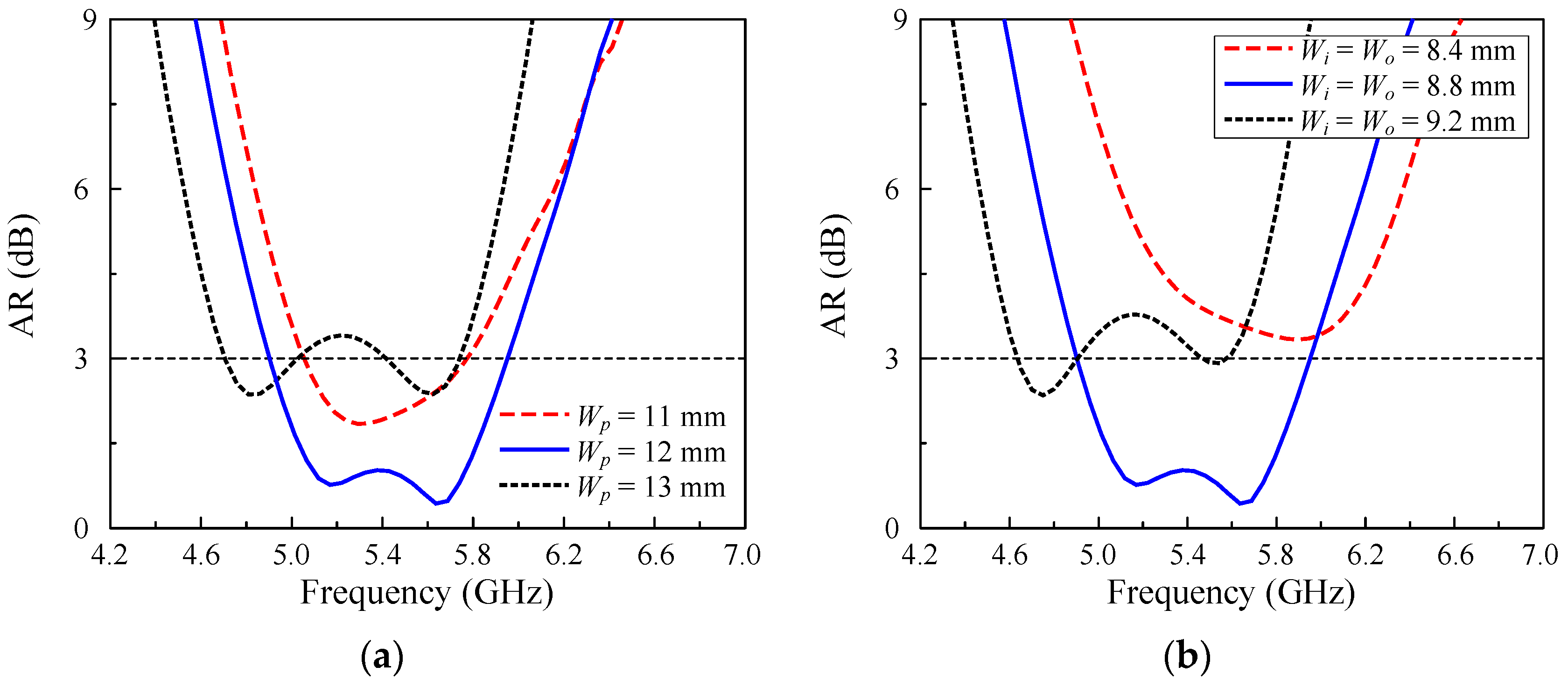
- Step 1: Design the truncated corner square patch with operation in the low-frequency band. The size Wp will have a strong effect on the operating frequency, and it is initially defined by Equation (1). Meanwhile, the AR value is tuned by the corner truncation parameter, d.
- Step 2: Design the unit cell with operation in the high-frequency band. The operating frequency can be predicted based on the dispersion diagram. The number of unit cells (N) is chosen as a trade-off between the antenna’s overall size and the gain. A higher gain can be achieved with a greater number of cells, but the antenna’s size is consequently increased.
- Step 3: Design the antenna with a uniform MS, tuning the patch size and unit cell size to allow operation at the desired band. The AR value is mainly determined by the truncation parameter d.
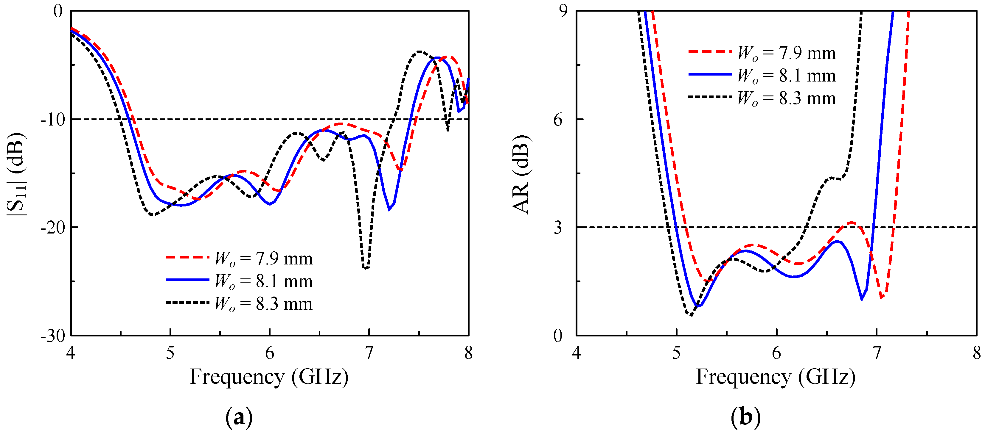
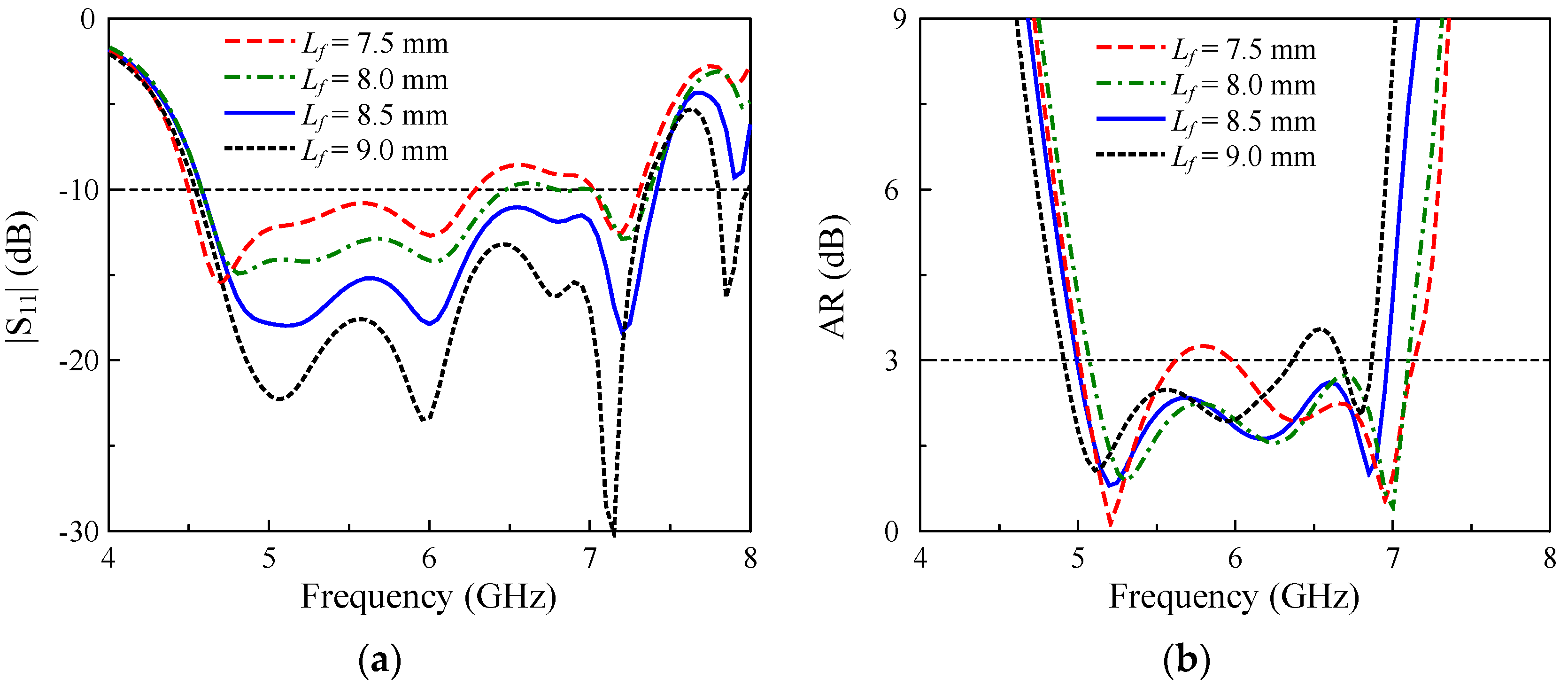
- Step 4: Design the antenna with a non-uniform MS. In this step, the size of the four center unit cells is slightly changed in comparison with the optimal value achieved in Step 3. Meanwhile, the size of the outer unit cells is significantly tuned for a higher CP operating band. The matching performance and the AR value are optimized by tuning the dimensions of the stub and the corner truncation of the patch.
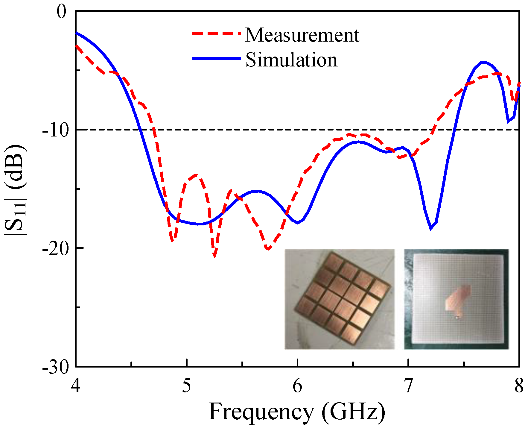
4. Measurement Results
5. Conclusions
Author Contributions
Funding
Conflicts of Interest
References
- Trinh-Van, S.; Yang, Y.; Lee, K.Y.; Kim, Y.S.; Hwang, K.C. Bandwidth-enhanced circularly polarized crescent-shaped slot antenna via circular-patch loading. Appl. Sci. 2019, 9, 1117. [Google Scholar] [CrossRef]
- Trinh-Van, S.; Thi, T.N.; Yang, Y.; Lee, K.Y.; Jung, K.Y.; Wang, K.C. High-gain waveguide-fed circularly polarized spidron fractal aperture antenna. Appl. Sci. 2019, 9, 691. [Google Scholar] [CrossRef]
- Rammal, M.; Majed, M.; Arnaud, E.; Andrieu, J.; Jecko, B. Small-size wide-band low-profile “pixel antenna”: Comparison of theoretical and experimental results in L band. Int. J. Antennas Propag. 2019, 3653270. [Google Scholar] [CrossRef]
- Sharma, P.C.; Gupta, K.C. Analysis and optimized design of single feed circularly polarized microstrip antennas. IEEE Trans. Antennas Propag. 1983, 31, 949–955. [Google Scholar] [CrossRef]
- Wu, J.; Hu, W.; Yin, Y.; Lian, R. Broadband circularly polarized antennas with center-slot-feeding. Microw. Opt. Technol. Lett. 2015, 57, 2793–2797. [Google Scholar] [CrossRef]
- Zhang, Y.Q.; Qin, S.T.; Qang, X.W.; Shang, F. Novel single-fed broadband circularly polarized antenna for GNSS applications. Int. J. RF Microw. Comput. Aided Eng. 2018, 28, e21193. [Google Scholar] [CrossRef]
- Wang, C.; Liu, H.; Zhang, X.; Zhu, S.; Wen, P.; Chen, G. Single-feed wideband circularly polarized patch antenna using dual mode defected ground waveguide coupling structure. Int. J. RF Microw. Comput. Aided Eng. 2019, 29, e21494. [Google Scholar] [CrossRef]
- Wu, J.; Ren, X.; Wang, Z.; Yin, Y. Broadband circularly polarized antenna with L-shaped strip feeding and shorting-pin loading. IEEE Antennas Wirel. Propag. Lett. 2014, 13, 1733–1736. [Google Scholar] [CrossRef]
- Mondal, T.; Maity, S.; Ghatak, R.; Chaudhuri, S.R.B. Design and analysis of a wideband circularly polarized perturbed psi-shaped antenna. IET Microw. Antennas Propag. 2018, 12, 1582–1586. [Google Scholar] [CrossRef]
- Li, J.; Liu, H.; Zhang, S.; Luo, M.; Zhang, Y.; He, S. A wideband single-fed, circularly-polarized patch antenna with enhanced axial ratio bandwidth for UHF RFID reader applications. IEEE Access 2018, 6, 55883–55892. [Google Scholar] [CrossRef]
- Yang, W.; Zhou, J.; Yu, Z.; Li, L. Single-fed low profile broadband circularly polarized stacked patch antenna. IEEE Trans. Antennas Propag. 2014, 62, 5406–5410. [Google Scholar] [CrossRef]
- Wu, J.; Yin, Y.; Wang, Z.; Lian, R. Broadband circularly polarized patch antenna with parasitic strips. IEEE Antennas Wirel. Propag. Lett. 2015, 14, 559–562. [Google Scholar] [CrossRef]
- Lin, Q.W.; Wong, H.; Zhang, X.Y.; Lai, H.W. Printed meandering probe-fed circularly polarized patch antenna with wide bandwidth. IEEE Antennas Wirel. Propag. Lett. 2014, 13, 654–657. [Google Scholar]
- Wong, H.; Lin, Q.W.; Lai, H.W.; Zhang, X.Y. Substrate integrated meandering probe-fed patch antennas for wideband wireless devices. IEEE Trans. Compon. Packag. Manuf. Technol. 2015, 5, 381–388. [Google Scholar] [CrossRef]
- Yang, Z.L.; Zhu, L.; Xiao, S. An implantable wideband circularly polarized microstrip patch antenna via two pairs of degenerate modes. IEEE Access 2019, 7, 4239–4247. [Google Scholar] [CrossRef]
- Liang, Z.; Ouyang, J.; Yang, F. Low-profile wideband circularly polarized single-layer metasurface antenna. Electron. Lett. 2018, 54, 1362–1364. [Google Scholar] [CrossRef]
- Ta, S.X.; Park, I. Low-profile broadband circularly polarized patch antenna using metasurface. IEEE Trans. Antennas Propag. 2015, 63, 5929–5934. [Google Scholar] [CrossRef]
- Nakamura, T.; Fukusako, T. Broadband design of circularly polarized microstrip patch antenna using artificial ground structure with rectangular unit cells. IEEE Trans. Antennas Propag. 2011, 59, 2103–2110. [Google Scholar] [CrossRef]
- Liu, S.; Yang, D.; Pan, J. Wideband circularly polarized patch antennas on reactive impedance substrates. IEEE Antennas Wirel. Propag. Lett. 2019, 18, 1395–1399. [Google Scholar] [CrossRef]
- Jash, S.S.; Goswami, C.; Ghatak, R. A low profile broadband circularly polarized planar antenna with an embedded slot realized on a reactive impedance surface. Int. J. Electron. Commun. (AEU) 2019, 108, 62–72. [Google Scholar] [CrossRef]
- Zhao, C.; Wang, C.F. Characteristic mode design of wide band circularly polarized patch antenna consisting of H-shaped unit cells. IEEE Access 2018, 6, 25292–25299. [Google Scholar] [CrossRef]
- Liu, S.; Yang, D.; Pan, J. A low-profile circularly polarized metasurface antenna with wide axial-ratio beamwidth. IEEE Antennas Wirel. Propag. Lett. 2019, 18, 1438–1442. [Google Scholar] [CrossRef]
- Juan, Y.; Yang, W.; Che, W. Miniaturized low-profile circularly polarized metasurface antenna using capacitive loading. IEEE Trans. Antennas Propag. 2019, 67, 3527–3532. [Google Scholar] [CrossRef]
- Chen, Q.; Zhang, H. Dual-patch polarization conversion metasurface-based wideband circular polarization slot antenna. IEEE Access 2018, 6, 74772–74777. [Google Scholar] [CrossRef]
- Tran, H.H.; Hussain, N.; Le, T.T. Low-profile wideband circularly polarized MIMO antenna with polarization diversity for WLAN applications. Int. J. Electron. Commun. (AEU) 2019, 108, 172–180. [Google Scholar] [CrossRef]
- Costa, F.; Luukkonen, O.; Simovski, C.R.; Monorchio, A.; Tretyakov, S.A.; de Maagt, P.M. TE surface wave resonances on high-impedance surface based antennas: Analysis and modeling. IEEE Trans. Antennas Propag. 2011, 59, 3588–3596. [Google Scholar] [CrossRef]
- Available online: http://www.mtginc.co.kr (accessed on 15 September 2020).


| Antennas | Overall Size (λo) | CP BW (%) | Gain (dBic) |
|---|---|---|---|
| Ref. [5] | 1.04 × 1.04 × 0.13 | 17.1 | 9.5 |
| Ref. [8] | 0.80 × 0.80 × 0.09 | 17.9 | 8.7 |
| Ref. [9] | 1.07 × 0.87 × 0.11 | 18.0 | 7.5 |
| Ref. [11] | 0.81 × 0.81 × 0.09 | 20.3 | 8.6 |
| Ref. [12] | 1.14 × 1.14 × 0.13 | 23.9 | 8.5 |
| Ref. [13] | 0.63 × 0.63 × 0.14 | 16.9 | 7.4 |
| Ref. [15] | 0.32 × 0.32 × 0.01 | 15.8 | N/G |
| Ref. [16] | 0.86 × 0.86 × 0.04 | 12.8 | 8.4 |
| Ref. [17] | 0.58 × 0.58 × 0.06 | 23.4 | 7.6 |
| Ref. [18] | 0.78 × 0.80 × 0.10 | 20.4 | 6.5 |
| Ref. [19] | 0.85 × 0.85 × 0.05 | 31.3 | 7.0 |
| Ref. [20] | 1.18 × 0.97 × 0.07 | 28.9 | 6.8 |
| Ref. [24] | 0.53 × 0.53 × 0.05 | 26.2 | 6.7 |
| Ref. [25] | 0.60 × 0.60 × 0.06 | 19.7 | 6.9 |
| Proposed | 0.80 × 0.80 × 0.06 | 30.0 | 7.6 |
Publisher’s Note: MDPI stays neutral with regard to jurisdictional claims in published maps and institutional affiliations. |
© 2020 by the authors. Licensee MDPI, Basel, Switzerland. This article is an open access article distributed under the terms and conditions of the Creative Commons Attribution (CC BY) license (http://creativecommons.org/licenses/by/4.0/).
Share and Cite
Le, T.T.; Tran, H.H.; Althuwayb, A.A. Wideband Circularly Polarized Antenna Based on a Non-Uniform Metasurface. Appl. Sci. 2020, 10, 8652. https://doi.org/10.3390/app10238652
Le TT, Tran HH, Althuwayb AA. Wideband Circularly Polarized Antenna Based on a Non-Uniform Metasurface. Applied Sciences. 2020; 10(23):8652. https://doi.org/10.3390/app10238652
Chicago/Turabian StyleLe, Tuan Tu, Huy Hung Tran, and Ayman Abdulhadi Althuwayb. 2020. "Wideband Circularly Polarized Antenna Based on a Non-Uniform Metasurface" Applied Sciences 10, no. 23: 8652. https://doi.org/10.3390/app10238652
APA StyleLe, T. T., Tran, H. H., & Althuwayb, A. A. (2020). Wideband Circularly Polarized Antenna Based on a Non-Uniform Metasurface. Applied Sciences, 10(23), 8652. https://doi.org/10.3390/app10238652