Article

Simplified Design of Magnetic Gear by Considering the Maximum Transmission Torque Line

by
Norhisam Misron
1,2,*,
Luqman Mohd Saini
1,*,
Ishak Aris
1,
Chockalingam Aravind Vaithilingam
3 and
Hanamoto Tsuyoshi
4
1
Faculty of Engineering, Universiti Putra Malaysia, Serdang 43400, Selangor, Malaysia
2
Institute of Advance Technology (ITMA) and Institute of Plantation Studies, Universiti Putra Malaysia, Serdang 43400, Selangor, Malaysia
3
HiRes Laboratory, School of Computer Science and Engineering, Taylor’s University, Subang Jaya 47500, Selangor, Malaysia
4
Department of Biological Functions Engineering, Graduate School of Life Science and Systems Engineering, Kyushu Institute of Technology, 2-4 Hibikino Wakamatsu-ku, Kitakyushu 808-0916, Japan
*
Authors to whom correspondence should be addressed.
Appl. Sci. 2020, 10(23), 8581; https://doi.org/10.3390/app10238581
Submission received: 2 October 2020 / Revised: 14 November 2020 / Accepted: 23 November 2020 / Published: 30 November 2020

Abstract

:
Magnetic gears (MGs) technology is studied widely among research institutions, with several improvements being documented. This development attracts a high amount of attention due to the demand in the development of magnetic gears towards higher performance than the conventional mechanical counterpart. In general, the design is complicated and there is a lack in detailed references for designing an MG for specific transmission torque as required by its application. Trial-and-error approaches have been the norm in achieving the desired torque by referring the existing MGs for the desired value of torque. This paper presents a new simplified approach towards designing an MG for the required torque and size by referring through a Maximum Transmission Torque Line (MTTL) reference. Finite element method (FEM) is used in analyzing randomly designed magnetic gears with various parameters towards the desired values of the MTTL. The proposed approach of MTTL is a new approach to estimate the total volume of permanent magnets (PMs) required for the MG to achieve the desired transmission torque. The reference line is used to generate equation relating the specific parameters of MG to develop the simplified design of MG based on the estimated total volume of PMs. This simplified way details to 8.5% of error in targeting the desired transmission torque, a means and way for the first stage of the MG design approach to reduce the conventional approaches.

1. Introduction

Since 1901, magnetic gears (MGs) have been developed as an alternative to the mechanical gear with the use of permanent magnetic force. Unlike mechanical gears, magnetic gears make a contactless speed conversion with a very efficient torque transmission performance, inherent to overload, reduced audible noise, and lubrication-less systems [1,2]. The transmission torque is an important output to meet the demand of its application, especially from the conversion of high-speed input to low-speed output.
In recent years, various magnetic gears have been developed in different configurations and concepts. The motivation lies with the impact of the magnetic gear technology with the capability to enter the industries sector. For example, a magnetic gear system with bigger torque capacity with reduced ripples through the flux modulator structure with linking bridges between them, which is known as modulating ring, is presented in References [3,4]. The triple permanent magnetic gear structure is introduced by Shan Peng [5], with improved magnetic energy density. Yiduan Chen [6] deployed additional permanent magnet (PM) poles in the stationary parts of the flux modulator, which acts like an extra magnetic gear for the same volume with increased transmitted torque. Another MG configuration that has been studied is the axial-type MG, which comprises a high-speed rotor, flux modulator, and low-speed rotor, which are all axially stacked to create an axial magnetic flux flow. This type of MG is suitable for an application that limits the size of the MG in radial length, since the performance depends on the axial length [7,8,9].
A transverse-flux-type MG has also been studied and analyzed by a few researchers [8,10,11]; this type has advantages over the conventional structure. However, the torque density for the transverse-flux MG is lower than that for the radial-type MG, as studied by Bomela [10], primarily due to the leakage in flux [11]. The axial-field flux-modulated MG proposed a new configuration where the high-speed and low-speed rotors are sandwiched between two flux modulators. This type of MG offered the advantages on applications that required isolation between input and output shaft, since it provides shorter gaps between the rotors, along with a simplified mechanical structure [12]. Besides using the MG for speed conversion of a motor, some researchers developed a new structure of MG with dual-iron ring which is integrated with a generator. The integration between the MG and generator produced higher power density for low-speed applications, such as wind turbine [13,14,15,16].
In most of the magnetic gears design, the output torque of the MGs is usually unpredictable due to the complications in its approach mathematically. Thus, there are no specific references to design a magnetic gear that can meet the torque required for its application at the very early stage. For instance, if the application requires a gear with 100 Nm of torque to be installed in a small space, the designer does not have a good reference in terms of the volume, size, and thickness of the permanent magnet (PM) to design an MG to meet the desired torque and size. In another case, a researcher needed to study the torque capabilities of a few MGs, to integrate them with a motor [17], or prototyping several number of models and testing their practicality before appropriate design evaluations can be arrived.
Among the most common approaches, such as trial-and-error and parametric optimizations, this proposed method is aimed to compute the maximum torque transmission value, using the Maximum Transmission Torque Line (MTTL) value. Therefore, a reference to present a simplified approach towards the design of coaxial magnetic gears is proposed to fulfill the torque requirement for its application, which this work attempts to present. By analyzing various designs of magnetic gears with random parameters, the characteristic of the transmission torque against the total volume of PM is obtained. From the characteristic, a Maximum Transmission Torque Line (MTTL) is formed that represents the highest torque achieved at every total volume of PMs. The parameters of MG can be obtained from an equation that established from the relationship between the total volume of PMs and the parameters. Thus, a simplified design of magnetic gear is developed based on the total volume of PMs that is referred by any selected transmission torque through the MTTL that is presented subsequently.

2. Maximum Transmission Torque Line of Magnetic Gear

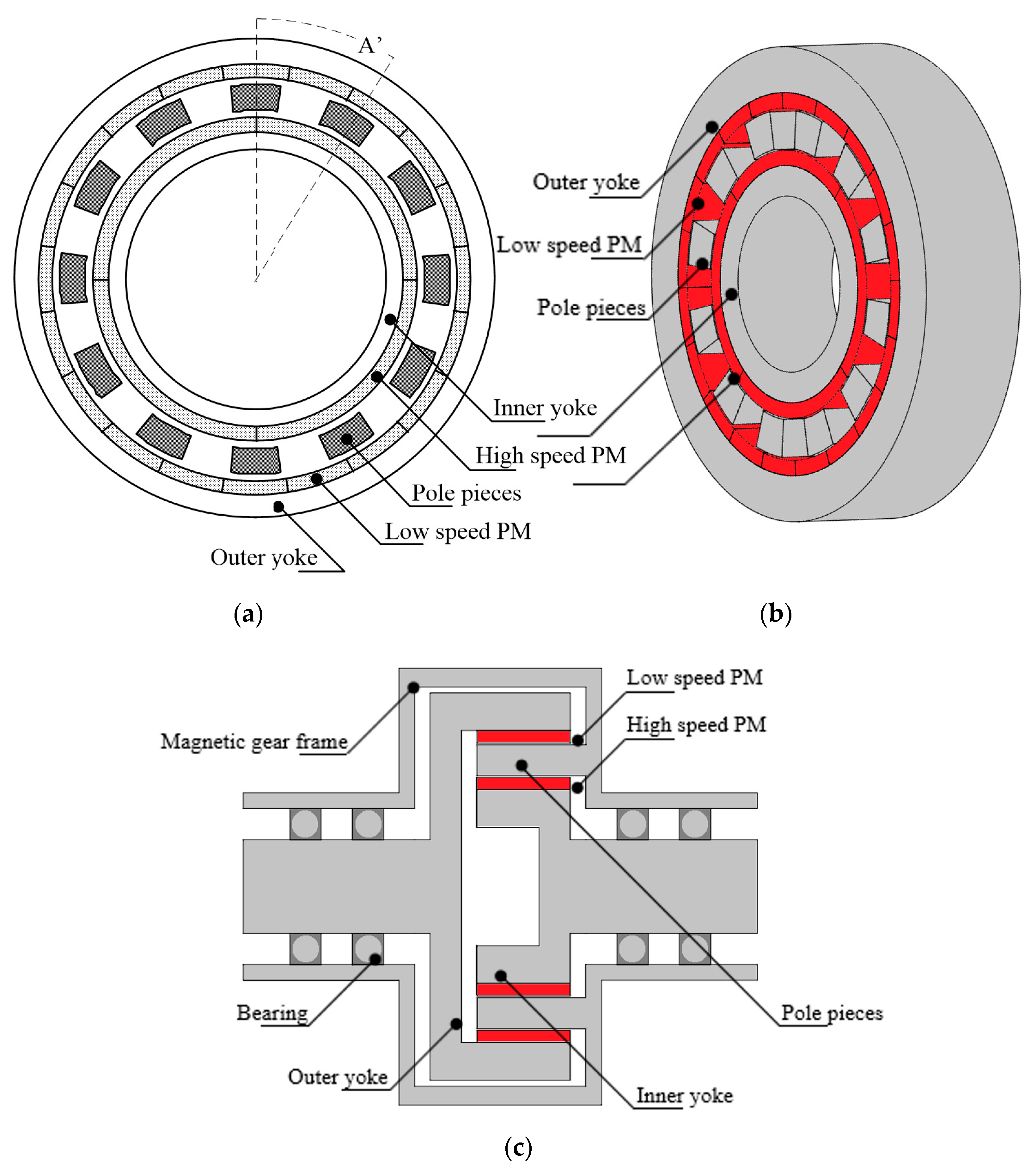
2.1. Magnetic Gear Type and Configuration

The coaxial type magnetic gears are analyzed with different and random parameters. Coaxial magnetic gears have the advantages on the number of pole pairs that engage between high-speed (HS) and low-speed (LS) rotors, which is higher than worm, rack pinion, bevel, spur, and planetary types of magnetic gears. The simple structure of the coaxial magnetic gear also gives an advantage for future work in developing the actual prototype, where the process of assembling the structure of an MG is not complicated. As shown in Figure 1a,b, the pole pieces are mounted directly to the stator part, while both moving parts, which are high-speed and low-speed rotors, have their own shaft that is mounted on the stator part through a pair of bearings.
A pair of bearings is used instead of single bearing, in order to avoid the misalignment of the shaft that can give adverse effects on the rotation of both rotors and the bearing itself. In this preliminary study, bearing loads were not taken into consideration, since they are not the critical part in a mechanical transmission [18].
As shown in Figure 1c, the coaxial magnetic gear consists of the pole pieces between the rotors which harmonize all the PMs that are contributed to torque transmission [19]. Surface-type PMs are used at both high-speed and low-speed rotors where the PMs are attached on the arc surface of the iron yoke of the rotors. The surface-type PM has a lower torque ripple compared with the interior-type PM [20]. Thus, the surface of the PMs is curved where the pole directions are outwards and inwards of the arc and are alternately arranged. The material used for the inner yoke, outer yoke, and pole pieces is 50H800, a soft magnetic iron. These cores are laminated in many sheets coated with zinc as the insulating layer, to avoid the eddy current that generates unwanted heat energy. The gear ratio concept for magnetic gears is similar to that of the mechanical gear on the desired speed conversion between the primary rotor and secondary rotor. The number of pole pairs of the PM at high speed or low speed is flexible as long as it is not changing the gear ratio. However, the ratio of pole pieces between high speed and low speed need to be related with the gear ratio, as seen in Equation (1).
G r   =   p ls p hs   =   n hs n ls
where Gr is the gear ratio, phs and pls are the number of pole-pairs at high-speed and low-speed rotors respectively, nhs and nls are the speed of high-speed and low-speed rotors respectively, and the negative sign represents the opposite direction of rotation of the high-speed and low-speed rotors.
Since the pole pieces are stationary, the directions of rotation for high-speed and low-speed rotors are opposite to each other where the pole pieces act as the carriers [21,22]. The number of iron pole pieces depends on the number of pole pairs of both high-speed and low-speed rotors, as seen in Equation (2).
N pp   =   p hs +   p ls   =   N hs + N ls 2
where Npp is the number of iron pole pieces, p hs is number of pole pairs at high-speed rotor, p ls is the number of pole pairs at low-speed rotor, Nhs is the number of PMs at the high-speed rotor, and Nls is the number of PMs at the low-speed rotor.

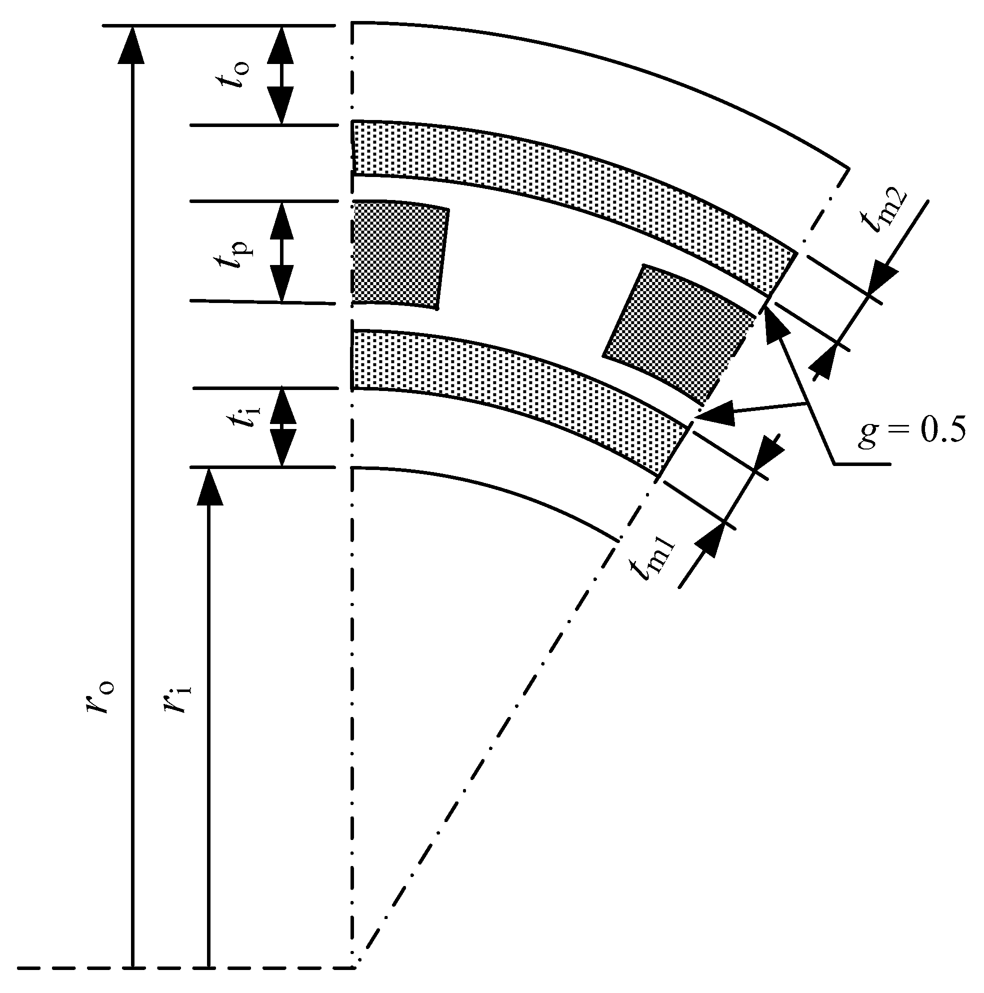
2.2. Design Parameters of Magnetic Gear

In this study, various magnetic gears were simulated with randomly different parameters. This was done to analyze the characteristic of transmission torque against the total volume of PM. However, a few parameters are fixed, as shown in Table 1, to ensure that the characteristic of the simulated magnetic gears are uniform. The gear ratio is fixed to 5:1, converting 1000 rpm speed of high-speed rotor to 200 rpm speed of low-speed rotor. This low gear ratio is suitable for the application with smaller torque improvement. However, a 25:1 ratio through double-stage gearing is considered high [23]. The reason 1000 rpm is used as the input speed is that most applications of gears are dependent on the speed of the prime mover as, for example, of the induction motor in References [24,25] and for DC motor [26] applications. The number of pole-pairs at high-speed rotor is 2, which required four PMs, while the number of pole-pairs at low-speed rotor is 10, which required 20 PMs. Thus, the number of pole pieces is 12, which is the sum of the number of pole pairs at both high-speed and low-speed rotors, as in Equation (2). The magnetic gears are designed with 0.5 mm air gaps between the rotors and the pole pieces, as the narrower air gaps increase the permeance and reduce the flux resistance. The 0.5 mm air gaps have no issue in assembling, since it is proven that smaller than that also can be achieved in assembling an electric machine [27].
Table 1 shows the fixed parameters, while the size of the magnetic gears’ structure, as shown in Figure 2, is a variable parameter. The changed parameters are the outer radius of MG, ro; inner radius of MG, ri; thickness of outer yoke, to; the thickness of PMs of low-speed rotor, tm2; the thickness of pole pieces, tp; the thickness of PMs at high-speed rotor, tm1; and the thickness of inner yoke, ti. The performance of the MGs is influenced by the parameters, and the observation on its effect on magnetic flux distribution is discussed in Section 3.1.

3. Maximum Transmission Torque Line and Design Parameters of Magnetic Gear

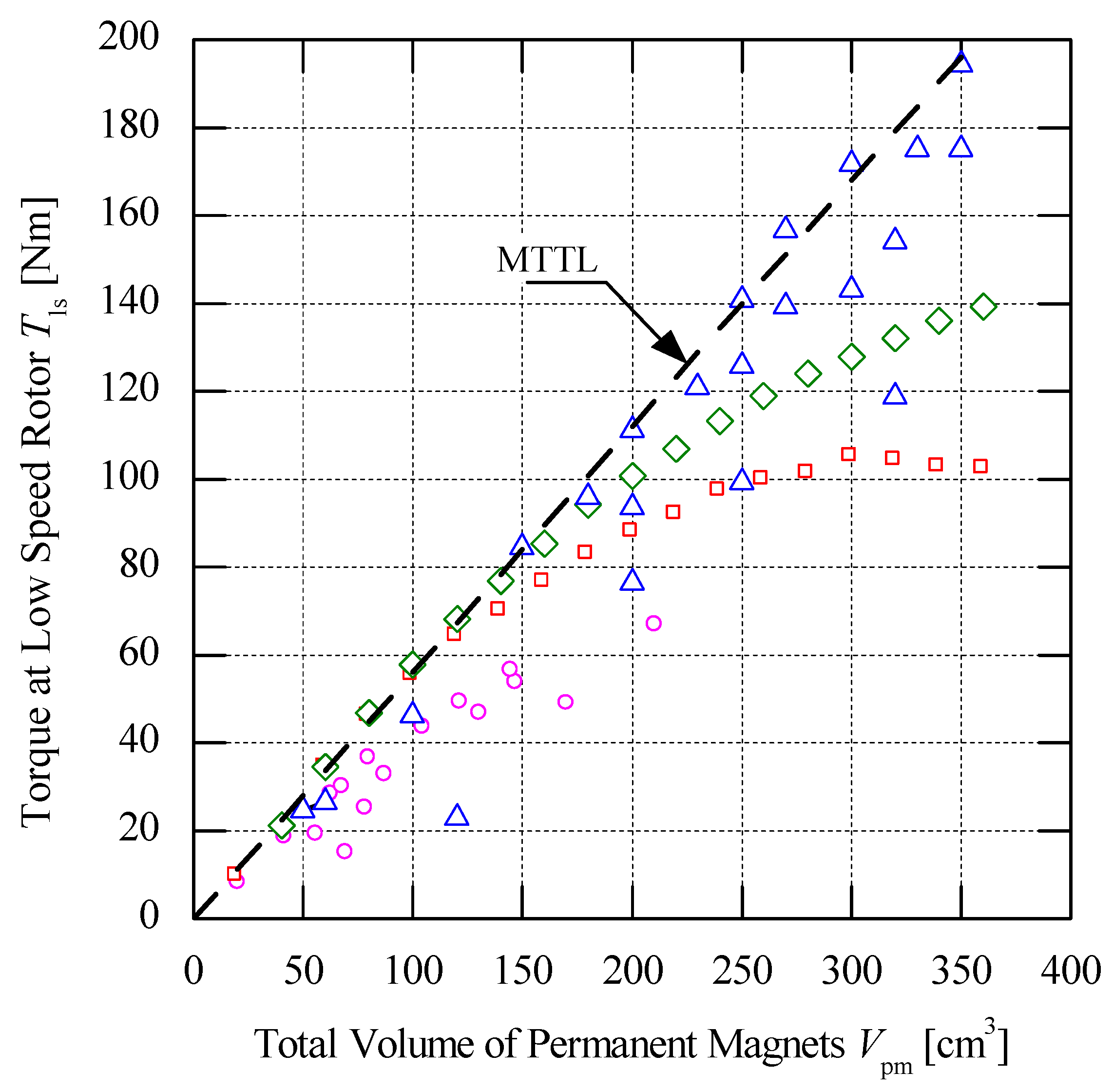
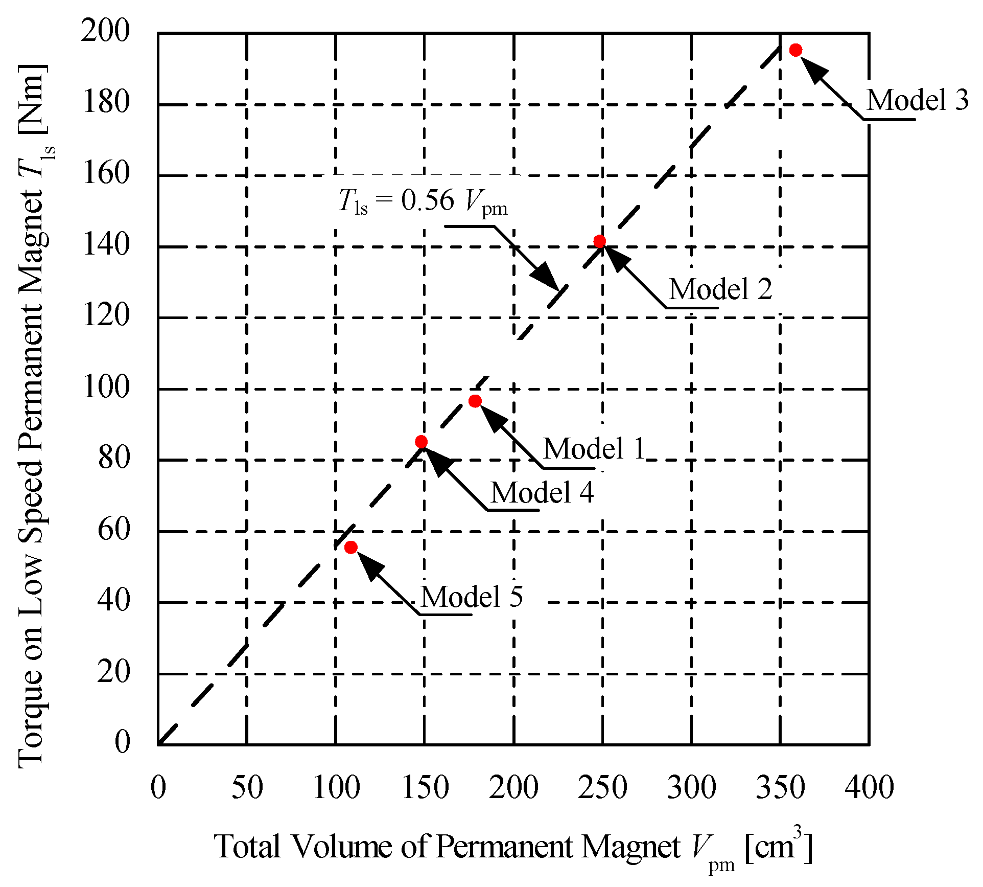
3.1. Maximum Transmission Torque Line

From the various designs of magnetic gears which followed the fixed conditions stated in Section 2.1, the analysis of the magnetic gears is conducted by using Finite Element Analysis Method (FEM) to study effect of volume of PM on the transmission torque. The total volume of PMs is varied by changing the parameters of MG, including the thickness of PMs. As shown in Figure 3, the circle symbols represent the MGs, with the thickness of PMs at high-speed rotor different and low-speed rotor and the size of MGs being fixed with a 164 mm outer diameter. At first, the data are varied by the increased thickness of PMs at low-speed rotor, while the thickness of PMs at high speed is fixed. The data are then varied with the thickness of PMs at high speed increasing, while, at low speed, the thickness is fixed. The changed thickness of PMs influences the volume of PMs where the transmission torque increases as the total volume of PMs increases. For the square symbols data, the diameter of MGs also fixed with 164 mm outer diameter, while the thickness of pole pieces is fixed to 10 mm.
The thickness of PMs at both high-speed and low-speed rotors is increased equivalently to observe the effect on transmission torque. From the observation, the transmission torque also increased and started to saturate at 100 Nm of transmission torque. For the diamond symbols data, the size of MGs is fixed at 200 mm outer diameter, and the thickness of PMs at both high-speed and low-speed rotors are also the same. The thickness of pole pieces is also the same as with previous data, i.e., 10 mm. By increasing the thickness of PMs, the transmission torque also increased and was higher than the MGs with the previous data, and it started to saturate at 140 Nm of transmission torque. Meanwhile the triangle symbols data are randomly designed MGs without a trend and a uniform increment in parameters. From the data analysis, it is observed that some of the MGs achieved a high transmission torque. This is due to a better flux distribution between PM that is resulting in higher torque transfer. The flux distribution is influenced by the size of the ferromagnetic iron in the magnetic gear which is needed to be optimized to avoid saturation of magnetic flux. The saturation of magnetic flux occurs because of the limitation of magnetic flux density in the iron, which is around 1.6 to 1.8 Tesla. The saturation of magnetic flux affects the performance of MG, thereby reducing the transmission torque, especially when the thickness of PM is increased, but the thickness of iron at outer yoke, inner yoke, and pole pieces remain the same.
From the obtained maximum points, a line which is named the Maximum Transmission Torque Line (MTTL) is created by connecting all the maximum points, as shown in Figure 3. The MTTL is the line of highest transmission torque value achieved at every total volume of PMs. The purpose is to have a reference in designing magnetic gears, using the total volume of PM corresponding to a specific torque that is suitable for its application. From the obtained MTTL, the relationship between the maximum transmission torque (Tls) and total volume of PMs (Vpm) is established, as in Equation (3).
T ls   =   0.56 V pm

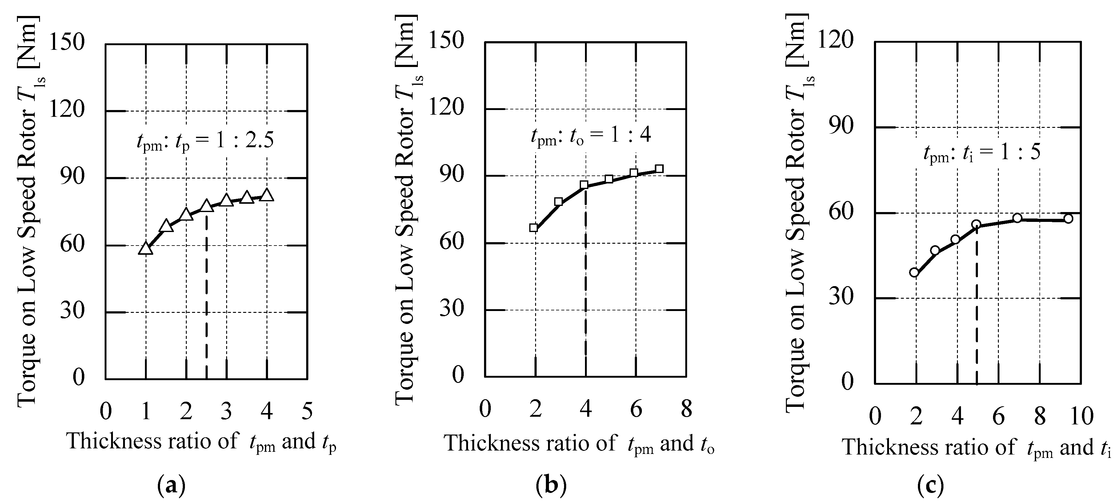
3.2. Relationship between the Parameter of Permanent Magnets and Irons

Based on Equation (3), which represents the MTTL, the total volume of PMs can be estimated from any required transmission torque. To obtain the parameters of MG from the estimated total volume of PMs, the relationship between the PMs and irons is identified. As discussed in Section 3.1, the study on the saturation of magnetic flux in the MG must be done to avoid the drop of transmission torque due to the saturation. Therefore, the thickness of irons is optimized through the simulation, to gain the best ratio between the thickness of PMs and irons.
Figure 4a shows the performance of analyzed MGs, where the size of pole pieces is varied, with different ratios between the thickness of the pole pieces, tp, and the PMs, tpm. Based on the observation, the best performance is achieved when the thickness of pole pieces is 2.5 times of the thickness of PMs, tpm, since, with more than that value, the increment begins to flatten. The thickness of the outer yoke, to was also tested from a few analyses of MGs which vary, with different ratios between the thickness of the outer yoke, to, and the PMs, tpm. By using the 160 cm3 total volume of PMs, the best ratio of to base on Figure 4b is four times the thickness of PMs, tpm, since, with more than that ratio, the increment of torque is also flattened, causing an increase of load on the MG structure. The same method is used in determining the best ratio between the thickness of inner yoke, ti, and PMs, tpm. The total volume of PM used for the simulation of the MGs is 100 cm3, where the best ratio for the thickness of inner yoke, ti, is five times the thickness of PMs, tpm. This is because, when the ratio was increased above that value, the increment of torque also started to flatten, reducing the efficiency of the MG, as shown in Figure 4c.
As a result, the best ratio was observed from the simulation is 1:2.5:4:5, which represents the thickness of PMs, pole pieces, outer yoke, and inner yoke, respectively. It is estimated that the best ratio was achieved due to the better magnetic flux distribution in the MG that increased the transmission torque. Thus, the saturation of magnetic flux can be avoided when the ratio is considered in designing the MG. From the obtained ratio, a few equations are generated, as shown in Equations (4)–(7).
tm1= tm2 = tpm
tp= 2.5tpm
to = 4tpm
ti = 5tpm
where tm1 and tm2 are the thickness of high-speed and low-speed PMs, respectively, which can be replaced with tpm since both values are same; to, tp, and ti are the thickness of outer yoke, pole pieces, and inner yoke iron which are generated from the ratio.

3.3. Relationship of Design Parameters

Based on Equation (3), which represents the MTTL, the total volume of PMs is estimated from any required transmission torque. Since the main purpose of this study was to develop a simplified MG that can meet the required transmission torque, the parameters of the structure of MG need to be obtained by relating the total volume of PMs with the parameters of the MG. Firstly, the total volume of PMs is derived as the sum of volume of PMs at high-speed and low-speed rotors, as expressed in Equation (8).
Vpm = Vm1 + Vm2
where Vm1 and Vm2 are the volume of PMs at low-speed rotor and high-speed rotor, respectively.
After separating both volume of PMs at both high-speed and low-speed rotor, each rotor equation is derived separately. By relating the volume of cylinder formula, the volume of PMs at low-speed rotor can be related to the parameters at low-speed rotor, consisting of the outer radius of outer rotor, the thickness of outer yoke, and the thickness of PMs at the low-speed rotor, as written in Equation (9). As shown in Equation (10), the thickness of the outer yoke, to, is eliminated by substituting Equation (6) into Equation (9).
Vm1= π(roto) 2ℓ − π(rototpm)2
Vm1= π(ro − 4tpm)2ℓ − π (ro − 5tpm)2
where Vm1 is the volume of PMs at low-speed rotor, ro is the outer radius of outer yoke of the magnetic gear, and ℓ is the length of the magnetic gear.
Same as the low-speed rotor, the volume of PMs at high-speed rotor can be related to the parameters at high-speed rotors which are the inner radius of inner rotor, thickness of inner yoke, and thickness of PMs at the high-speed rotor, given as Equation (11). By substituting Equation (7) into Equation (11), the thickness of inner yoke, ti, can be eliminated as shown in Equation (12).
Vm2= π(ri + ti + tpm)2ℓ − π(ri + ti)2
Vm2= π(ri + 6tpm)2ℓ − π(ri + 5tpm)2
where Vm2 is the volume of PMs at high-speed rotor, while ri is the inner radius of the inner yoke.
Equation (13) shows the combination of fixed value of air gap, g, with the thickness of pole pieces, tpm, as c, which represents the space between the PMs of high-speed and low-speed rotor.
c = tp + 2g; c = 2.5tpm + 1
where g is the air gap between both high-speed and low-speed rotors and the pole pieces, while c is the combination of g with the thickness of pole pieces, tp.
To simplify Equations (10) and (12), an equation can be formed by relating the inner radius with the outer radius, as written in Equations (14) and (15).
ri = rototm2ctm1ti
ri= ro − 13.5tpm − 1
Subsequently, the Vm2 value is as shown in Equation (16).
Vm2= π(ro − 7.5tpm1)2ℓ − π(ro − 8.5tpm − 1)2
The net Vpm is as shown in Equation (17), and its quadratic representation is in Equation (18), where the thickness of PMs, tpm, is unknown.
Vpm= [π(ro − 4tpm)2ℓ − π(ro − 5tpm)2ℓ] + [π(ro − 7.5tpm1)2ℓ − π(ro − 8.5tpm − 1)2ℓ]
25 t pm 2     ( 4 r o     2 ) t pm   + V pm π   =   0
To solve the quadratic in Equation (18), the quadratic formula is used, resulting in Equation (19). Thus, the thickness of PMs is obtained from the estimated total volume of PMs that corresponds to the desired transmission torque through the MTTL. The radius and the length of magnetic gear are chosen according to the applications. The other parameters, which are the thickness of outer yoke, pole pieces, and inner yoke of the simplified MG, can be obtained by substituting thickness of PMs into it. Hence, the relationship between the total volume of PMs and the parameters in the MG can be obtained from Equation (19), which is expressed as Equation (20), respectively.
t pm   =   ( 4 r o 2 ) 50 ( 2 4 r o ) 2 100 V pm π 50
V pm = π ( ( 4 r o 2 ) 50 t pm ) 2 100

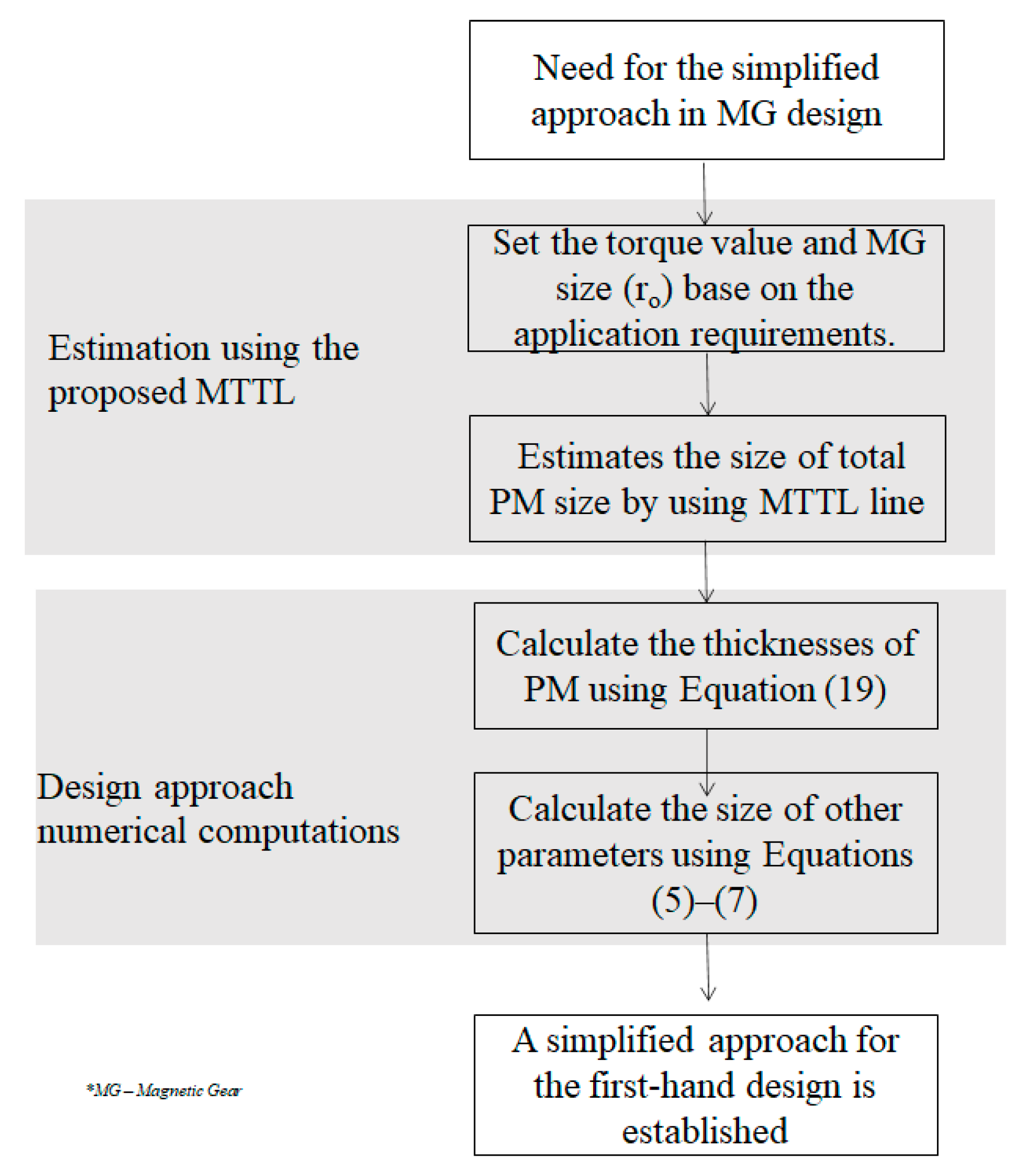
3.4. Design Process Based on MTTL

An MG can be design in a simplified way since all the parameters of the MG can be obtained from the equations that were derived in Section 3.3. The design process based on the proposed approach is illustrated in Figure 5. Firstly, the transmission torque and size of the MG have to be decided by a designer based on the requirement of their application, where the size is consist of the outer radius, ro, and the axial length of the MG, . Secondly, for the total volume of PM, Vpm is estimated from the required transmission torque, and Tls through the MTTL (as in Equation (3)). Thirdly, for the thickness of the PM, tpm is obtained from Equation (19) from the substitution of ro, , and Vpm. Lastly, other parameters, which are the thickness of outer yoke, to, pole pieces, tp, and inner yoke, ti, are obtained from the substitution of the tpm into Equations (5)–(7), respectively. From all the parameters obtained, a simplified design of MG is achieved, where the MTTL plays an important role in this approach, to gain the entire parameters of the MG.

4. Validation of Simplified Design of Magnetic Gear

4.1. Design Condition

To prove that the MTTL is relevant for designing surface type magnetic gear, it was tested with a few magnetic gear models, using Equation (20). Thus, five models of magnetic gears were randomly designed with different conditions, to validate the relevancy of the proposed approach, considering the MTTL. The fixed conditions, as shown in Figure 1, were followed in designing the models, since the MTTL is limited by those conditions. As shown in Table 2, every requirement of the models consists of a specific targeted transmission torque and required radius of MG that represent various type of applications at random. Model 1 and Model 4 required 160 mm diameter and targeted 100 Nm and 85 Nm of transmission torque for the MG, respectively. Meanwhile, Model 2 required 140 Nm of torque with 240 mm diameter of the MG. Model 3 targeted 200 Nm of transmission torque and 390 mm diameter of MG. Lastly, Model 5 required 120 mm of diameter and targeted 60 Nm of transmission torque. From the specific targeted torque, the total volume of PMs is obtained through the MTTL while the thickness of PM and other parameters are obtained from the substitution of the required radius of MG, total volume of PMs, and the length of MG into the equations that were derived in Section 3. Thus, all the models were designed based on the obtained parameters shown in Table 2 and analyzed by using FEM, to get the result of simulated transmission torque. By comparing the simulated and targeted transmission torque of the models, the percentage of error is obtained to correlate with the relevancy of the MTTL for designing coaxial magnetic gear.

4.2. Validation of Design Analysis

The performance of an MG depends on the total volume of PMs used and the magnetic flux flowing through the structure of the MG. If the total volume of PMs is high but the magnetic flux densities are saturated inside the MG, the performance is lower than the MG that has a smaller total volume of PMs but a better magnetic flux density. Thus, the MTTL represents the highest performance of MG achieved at every total volume of PMs used in the MGs. As shown in Figure 6, the simulated data of the tested models are plotted on the MTTL, to observe the errors. It is observed that the simulated transmission torque of the models is very close to the targeted value that can be seen from the plotted data of the models which are closed to the MTTL. The percentages of errors are calculated to represent the inaccuracy of the proposed reference which is the MTTL. The lowest percentage of error is achieved by Model 2 and Model 4, which is only 0.6%. Model 2 targeted 140 Nm of transmission torque and achieved 140.8 Nm for a magnetic gear with 120 mm required radius, while Model 4 targeted 85 Nm of torque and achieved 84.5 Nm with the same required radius. The MG with the highest percentage of error is Model 5, which has 8.5% from 95.9 Nm of simulated transmission torque instead of 100 Nm of targeted transmission torque. This shows that the percentage of error of the simulated transmission torque of the MG design which referred from the MTTL can reach up to 8.5%, which is considered to be a small error.
Table 3 shows the structure of tested models with the simulated result based on the conditions created from Table 2 for the design verification. As shown in Table 3, the magnetic flux flow of all models has the same pattern since the configuration and gear ratios of the MGs are fixed. From the magnetic flux densities, it is observed whether the models have saturated magnetic flux or not. Based on the observation, the highest flux densities can be seen at Model 3, where the flux density on the iron parts reached 1.8 Tesla. Since the transmission torque of the model is high, it is assumed that the magnetic flux density has not over-passed the 1.8 Tesla, which is considered the maximum flux density. Model 2 and Model 4 show almost the same maximum flux density, which is around 1.6 Tesla, while Model 1 shows a lower maximum flux density, which is around 1.4 Tesla, and the lowest flux density is achieved by Model 5, at around 1.35 Tesla. In a paper that studied a novel magnetic geared generator, the flux density also shows around 1.8 Tesla maximum density is achieved [13]. Thus, it is considered that all the models have a good magnetic flux distribution, since the appearance of the red region on the flux densities are not significant. This is due to the proposed ratio of thickness of the PMs and the iron parts of MG, which as expressed in Section 3.2, have considered the saturation of magnetic flux.
The approach has limitations, i.e., the conditions that were stated in Table 1. Even though it has fixed conditions, the approach still can be used in many applications, since the chosen conditions are general, as discussed in Section 2.1. Therefore, designers have to follow the fixed conditions, especially on the dynamic behavior, to ensure that the MG can meet the desired transmission torque. It is proven that the results validation with two-dimensional Finite Element Model (FEM) of JSOL Corporation, Tokyo, Japan, the JMAG-Designer® software shows the accuracy and efficiency of the proposed approach. Since the modeling tool is a powerful piece of software that our lab has extensively used for a number of prototype development for the past several years, it can be assumed that the result obtained is optimistic, with less error, even between the 2D and 3D results. In a study on a motor [28], the performance was evaluated with the numerical tool for simulation, and the result showed the maximum torques generated are 1.17 Nm (2D simulation) and 1.13 Nm (Measurement), which is about 96.4% accurate. However, the proposed approach needs to be validated with actual prototypes through experiment in future work.

5. Conclusions

A simplified method for designing a magnetic gear through the estimation on the total volume for the desired transmission torque, using the MTTL approach, was presented. The MTTL was developed from various analyses of magnetic gears with randomly different parameters, where the line is formed by maximum value of torque at every total volume of PMs. The equation of relationship between total volume of PMs and parameters of MG was derived to determine the parameters of MG from the estimated total volume of PMs, and the required radius to achieve the required transmission torque was derived. The MTTL was validated with five models that represent different requirements in applications. The result shows up to 8.5% of error in targeting the desired transmission torque from the models that referred to the MTTL. The proposed MTTL is relevant to be the reference in designing any surface-type PM coaxial magnetic gears that give an early approach in the direction of magnetic gear design. Thus, it helps the magnetic gear designer to design the magnetic gear that fulfills the required transmission torque instead of resulting in an unpredictable performance.

Author Contributions

Conceptualization, N.M. and L.M.S.; methodology, N.M. and L.M.S.; software, N.M. and L.M.S.; resources, N.M. and L.M.S; data curation, N.M. and L.M.S.; writing—original draft preparation, N.M. and L.M.S.; writing—review and editing, I.A., C.A.V., and H.T. All authors have read and agreed to the published version of the manuscript.

Funding

This research is funded by the Ministry of Education, Malaysia for financial support under the “Translational Research” Grant (TR@M).

Acknowledgments

The authors would like to express their gratitude to Universiti Putra Malaysia for the facilities provided during the research work.

Conflicts of Interest

The authors declare no conflict of interest.

Abbreviations

FEMFinite element method
DCDirect current
Axial length of magnetic gear
gAir gap length
GrGear ratio
MGMagnetic gear
MTTLMaximum Transmission Torque Line
nhsSpeed of high-speed rotor
NhsNumber of permanent magnets at high-speed rotor
nlsSpeed of low-speed rotor
NlsNumber of permanent magnets at low-speed rotor
NppNumber of pole pieces
PMPermanent magnet
phsNumber of pole pairs at high-speed rotor
plsNumber of pole pairs at low-speed rotor
riInner radius of magnetic gear
roOuter radius of magnetic gear
tiThickness of inner yoke
tm1Thickness of permanent magnet at high-speed rotor
tm2Thickness of permanent magnet at low-speed rotor
TlsAverage torque at low-speed rotor (transmission torque)
toThickness of outer yoke
tpThickness of pole pieces
tpmThickness of permanent magnet
Vm1Volume of permanent magnet at low-speed rotor
Vm2Volume of permanent magnet at high-speed rotor
VpmTotal volume of permanent magnet

References

  1. Rasmussen, P.O.; Andersen, T.O.; Jorgensen, F.T.; Nielsen, O. Development of a high-performance magnetic gear. IEEE Trans. Ind. Appl. 2005, 41, 764–770. [Google Scholar] [CrossRef]
  2. Kowol, M.; Kołodziej, J.; Gabor, R.; Łukaniszyn, M.; Jagieła, M. On-load characteristics of local and global forces in Co-Axial magnetic gear with reference to additively manufactured parts of modulator. Energies 2020, 13, 3169. [Google Scholar] [CrossRef]
  3. Zhan, Y.; Ma, L.; Wang, K.; Zhao, H.; Xu, G.; Ding, N. Torque analysis of concentric magnetic gear with interconnected flux modulators. IEEE Trans. Magn. 2019, 55, 1–4. [Google Scholar] [CrossRef]
  4. Jian, L.; Deng, Z.; Shi, Y.; Wei, J.; Chan, C.C. The mechanism how coaxial magnetic gear transmits magnetic torques between its two rotors: Detailed analysis of torque distribution on modulating ring. IEEE/ASME Trans. Mechatron. 2019, 24, 763–773. [Google Scholar] [CrossRef]
  5. Peng, S.; Fu, W.N.; Ho, S.L. A novel high torque density triple permanent magnet excited magnetic gear. IEEE Trans. Magn. 2014, 50, 1–4. [Google Scholar] [CrossRef]
  6. Chen, Y.; Fu, W.N.; Li, W. Performance analysis of a novel triple-permanent-magnet-excited magnetic gear and its design method. IEEE Trans. Magn. 2016, 52, 1–4. [Google Scholar] [CrossRef]
  7. Acharya, V.M.; Bird, J.Z.; Calvin, M. A flux focusing axial magnetic gear. IEEE Trans. Magn. 2013, 49, 4092–4095. [Google Scholar] [CrossRef]
  8. Chen, Y.; Fu, W.N.; Ho, S.L.; Liu, H. A quantitative comparison analysis of radial-flux, transverse-flux, and axial-flux magnetic gears. IEEE Trans. Magn. 2014, 50, 1–4. [Google Scholar] [CrossRef]
  9. Ruiz-Ponce, G.E.; Arjona, M.A.; Hernández, C.; Espinoza, C. Modeling of an axial-type magnetic gear using a reluctance-based magnetic equivalent circuit. In Proceedings of the IEEE Conference on Electromagnetic Field Computation (CEFC), Miami, FL, USA, 13–16 November 2016. [Google Scholar]
  10. Bomela, W.; Bird, J.Z.; Acharya, V.M. The performance of a transverse flux magnetic gear. IEEE Trans. Magn. 2014, 50, 1–4. [Google Scholar] [CrossRef]
  11. Li, X.; Liu, S.; Wang, Y.; Fan, Y. Investigation of the flux leakage effects in transverse-flux magnetic gear. In Proceedings of the 20th International Conference on Electrical Machines and Systems (ICEMS), Sydney, Australia, 11–14 August 2017. [Google Scholar]
  12. Zhu, D.; Yang, F.; Du, Y.; Xiao, F.; Ling, Z. An axial-field flux-modulated magnetic gear. IEEE Trans. Appl. Supercond. 2016, 26, 1–5. [Google Scholar] [CrossRef]
  13. Mustafa, S.S.; Misron, N.; Othman, M.L.; Tsuyoshi, H. Power characteristics analysis of a novel double-stator magnetic geared permanent magnet generator. Energies 2017, 10, 2048. [Google Scholar] [CrossRef] [Green Version]
  14. Mustafa, S.S.; Misron, N.; Mariun, N.; Othman, M.L.; Hanamoto, T. Torque distribution characteristics of a novel double-stator permanent magnet generator integrated with a magnetic gear. Energies 2017, 10, 2. [Google Scholar] [CrossRef] [Green Version]
  15. Mustafa, S.S.; Misron, N.; Mariun, N.; Othman, M.L.; Hanamoto, T. A novel double-stator permanent magnet generator integrated with a magnetic gear. Prog. Electromagn. Res. 2016, 49, 69–80. [Google Scholar]
  16. Salihu, S.M.; Misron, N.; Othman, M.L.; Hanamoto, T. Power density evaluation of a novel double-stator magnetic geared permanent magnet generator. Prog. Electromagn. Res. 2018, 80, 19–36. [Google Scholar] [CrossRef] [Green Version]
  17. Rasmussen, P.O.; Mortensen, H.H.; Matzen, T.N.; Jahns, T.M.; Toliyat, H.A. Motor integrated permanent magnet gear with a wide torque-speed range. In Proceedings of the IEEE Energy Conversion Congress and Exposition (ECCE), San Jose, CA, USA, 20–24 September 2009; pp. 1510–1518. [Google Scholar]
  18. Guo, L.; Parsa, L. Effects of magnet shape on torque characteristics of Interior Permanent Magnet machines. In Proceedings of the IEEE Electric Ship Technologies Symposium, Baltimore, MD, USA, 20–21 April 2009; pp. 93–97. [Google Scholar]
  19. Mezani, S.; Atallah, K.; Howe, D. A high-performance axial-field magnetic gear. J. Appl. Phys. 2016, 99, 08R303. [Google Scholar] [CrossRef]
  20. Diez-Jimenez, E.; Sanchez-Montero, R.; Martinez-Muñoz, M. Towards miniaturization of magnetic gears: Torque performance assessment. Micromachines 2018, 9, 16. [Google Scholar] [CrossRef] [PubMed] [Green Version]
  21. Wu, Y.C.; Jian, B.S. Magnetic field analysis of a coaxial magnetic gear mechanism by two-dimensional equivalent magnetic circuit network method and finite-element method. Appl. Math. Model. 2015, 39, 5746–5758. [Google Scholar] [CrossRef]
  22. Atallah, K.; Howe, D. A novel high-performance magnetic gear. IEEE Trans. Magn. 2001, 37, 2844–2846. [Google Scholar] [CrossRef] [Green Version]
  23. Floris, A.; Serpi, A.; Porru, M.; Fois, G.; Damiano, A. Design of a double-stage magnetic gear for high-speed electric propulsion systems. In Proceedings of the 2018 23rd International Conference on Electrical Machines (ICEM), Alexandroupoli, Greece, 3–6 September 2018. [Google Scholar]
  24. Etemadi, M.; Haghighian, R. Design optimization of wound rotor induction motor using genetic algorithm. In Proceedings of the 2019 5th Conference on Knowledge Based Engineering and Innovation (KBEI), Tehran, Iran, 28–29 February 2019; pp. 827–832. [Google Scholar]
  25. Nistor, C.G.; Cloţea, L.R. Separation of total noise (on components) for an optimal design of IE3 premium efficiency motor. In Proceedings of the 2017 International Conference on Optimization of Electrical and Electronic Equipment (OPTIM) & 2017 International Aegean Conference on Electrical Machines and Power Electronics (ACEMP), Brasov, Romania, 25–27 May 2017; pp. 501–508. [Google Scholar]
  26. Oancea, C.D.; Petre, V.C.; Boicea, V. Testing equipment for DC Motor. In Proceedings of the 2018 International Conference and Exposition on Electrical and Power Engineering (EPE), Iasi, Romania, 18–19 October 2018; pp. 17–20. [Google Scholar]
  27. Ai, C.; Lee, C.H.; Kirtley, J.L.; Huang, Y.; Wang, H.; Zhang, Z. A hybrid methodology for analyzing the performance of induction motors with efficiency improvement by specific commercial measures. Energies 2019, 12, 4497. [Google Scholar] [CrossRef] [Green Version]
  28. Vaithilingam, C.A.; Misron, N.; Zare, M.R.; Aris, I.; Marhaban, M.H. Computation of electromagnetic torque in a double rotor switched reluctance motor using flux tube methods. Energies 2012, 5, 4008–4026. [Google Scholar] [CrossRef]
Figure 1. Structure of surface type permanent magnet (PM) coaxial magnetic gear: (a) two-dimensional structure, (b) three-dimensional structure, and (c) the two-dimensional structure including the bearing and shaft parts.
Applsci 10 08581 g001
Figure 2. Parameters of surface type of PM concentric magnetic gear.
Applsci 10 08581 g002
Figure 3. The characteristic of transmission torque against the total volume of PMs.
Applsci 10 08581 g003
Figure 4. The transmission torque influenced by the thickness ratio of (a) tpm and tp, (b) tpm and to and (c) tpm and ti.
Applsci 10 08581 g004
Figure 5. The process of designing a magnetic gear (MG), using the approach.
Applsci 10 08581 g005
Figure 6. The simulated result of the models on the Maximum Transmission Torque Line (MTTL).
Applsci 10 08581 g006
Table 1. Value of fixed parameters of the magnetic gears.
Design ParameterValue
Gear ratio, Gr5:1
Speed of high-speed rotor, nhs1000 rpm
Speed of low-speed rotor, nls200 rpm
Number of pole-pairs at HS rotor, phs2
Number of pole-pairs at LS rotor, pls10
Number of pole pieces. Npp12
Length of air gap, g0.5 mm
Table 2. The conditions and parameters for design verification of magnetic gears.
ModelDesign RequirementEstimated Parameter
Transmission Torque, Tls (Nm)Outer Radius, Ro (mm)Vpm (cm3) (mm)tpm (mm)tp (mm)to (mm)ti (mm)
110080179703.38.313.216.5
2140120250504.511.318.022.5
3200195357306.015.024.030.0
485120152304.511.318.022.5
56060107703.07.512.015.0
Table 3. The magnetic flux density and flux flow of the models.
Structure of MG (Units: mm) Applsci 10 08581 i001Flux FlowTransmission Torque
Model 1 Applsci 10 08581 i002 Applsci 10 08581 i003 Applsci 10 08581 i004Targeted = 100 Nm
Simulation = 95.9 Nm
Percentage difference = 4.1%
Model 2 Applsci 10 08581 i005 Applsci 10 08581 i006 Applsci 10 08581 i007Targeted = 140 Nm
Simulation = 140.8 Nm
Percentage difference = 0.6%
Model 3 Applsci 10 08581 i008 Applsci 10 08581 i009 Applsci 10 08581 i010Targeted = 200 Nm
Simulation = 194.4 Nm
Percentage difference = 2.8%
Model 4 Applsci 10 08581 i011 Applsci 10 08581 i012 Applsci 10 08581 i013Targeted = 80 Nm
Simulation = 84.5 Nm
Percentage difference = 0.6%
Model 5 Applsci 10 08581 i014 Applsci 10 08581 i015 Applsci 10 08581 i016Targeted = 60 Nm
Simulation = 54.9 Nm
Percentage difference = 8.5%
Publisher’s Note: MDPI stays neutral with regard to jurisdictional claims in published maps and institutional affiliations.

