Journal Bearing: An Integrated CFD-Analytical Approach for the Estimation of the Trajectory and Equilibrium Position


Abstract
1. Introduction
2. Materials
3. Methods
3.1. Computational Fluid Dynamics
3.2. Dynamics
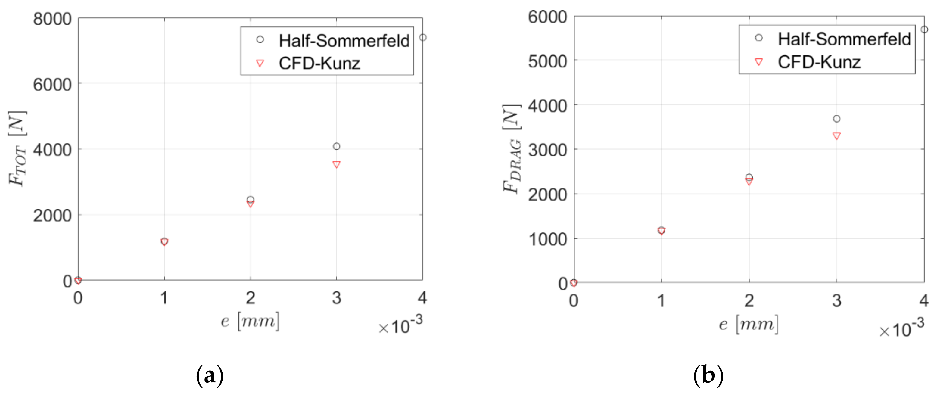
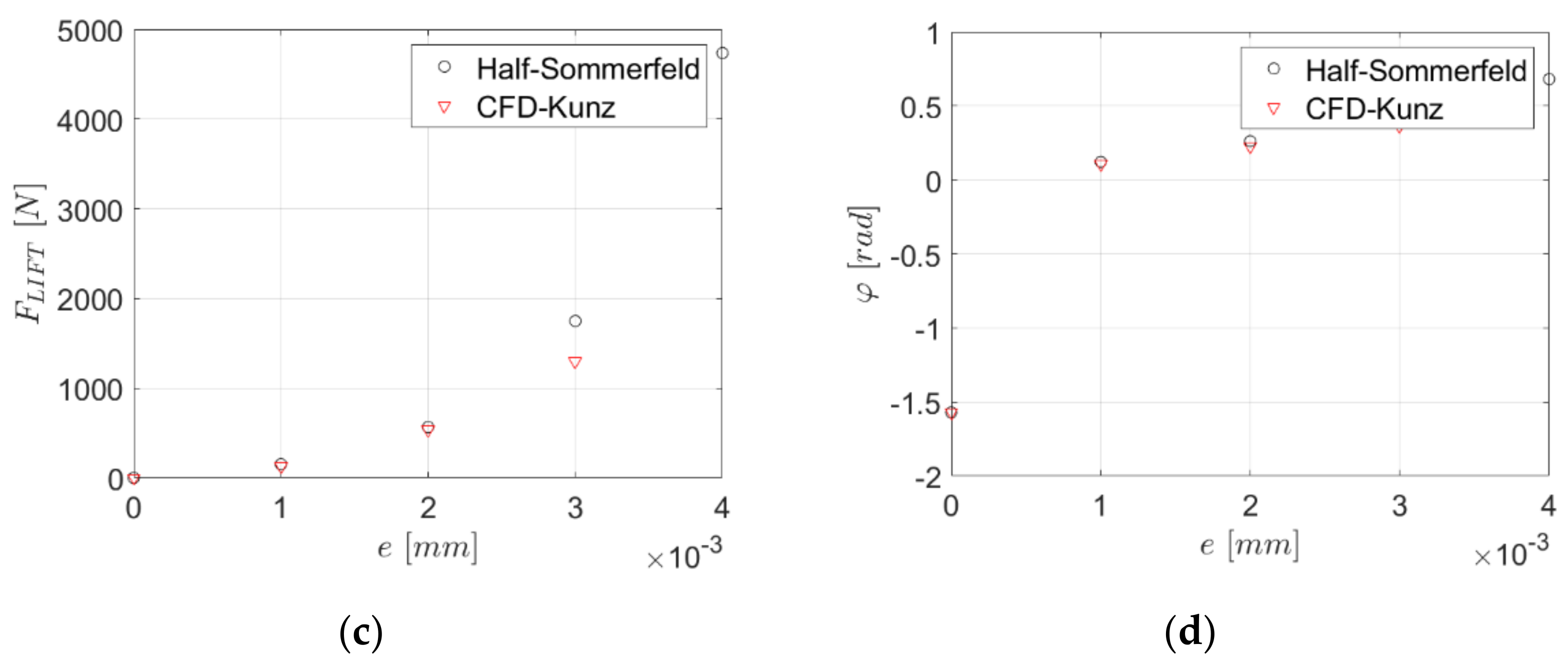
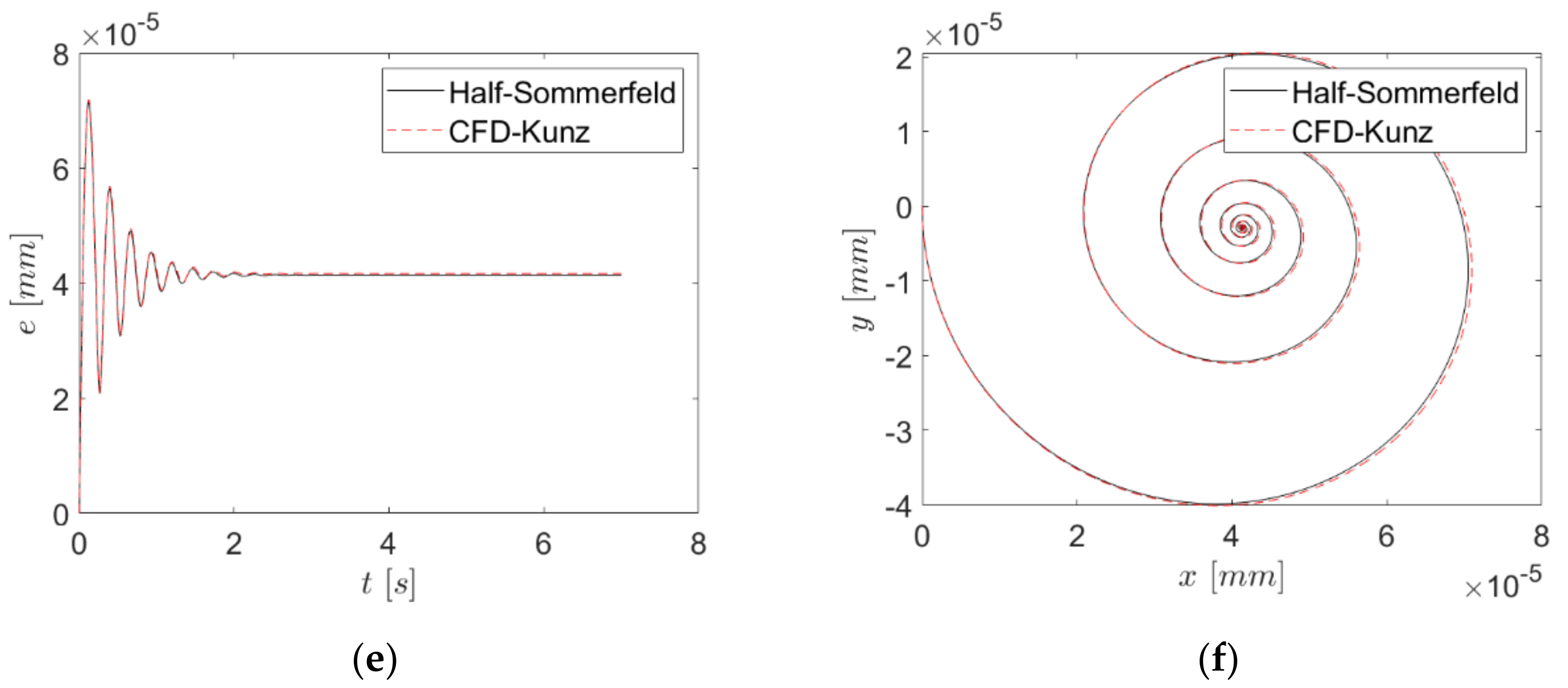
4. Discussion
5. Performance Enhancements
6. Conclusions
Funding
Conflicts of Interest
References
- Sommerfeld, A. The hydrodynamic theory of lubrication friction. Z. Math. Phys. 1904, 97, 50. [Google Scholar]
- Swift, H.W. The full journal bearing. Proc. Inst. Mech. Eng. 1931, 233, 267. [Google Scholar]
- Gao, G.; Yin, Z.; Jiang, D.; Zhang, X. Numerical analysis of plain journal bearing under hydrodynamic lubrication by water. Tribol Int. 2014, 75, 31–38. [Google Scholar]
- Jakobsson, B.; Floberg, L. The finite journal bearing, considering vaporization ((Das Gleitlager von endlicher Breite mit Verdampfung). Mater. Sci. 1957, 130, 3. [Google Scholar]
- Gumbel, L. Monatsblatter Berlin Bezirksver. Berl. Bez. 1914, 5, 159–174. [Google Scholar]
- Dowson, D. A generalized Reynolds equation for fluid-film lubrication. Int. J. Mech. Sci. 1962, 4, 159–170. [Google Scholar]
- Raimondi, A.A.; Boyd, J. A solution for the finite journal bearing and its application to analysis and design: I. ASLE Trans. 1958, 1, 159–174. [Google Scholar]
- Raimondi, A.A.; Boyd, J. A solution for the finite journal bearing and its application to analysis and design: II. ASLE Trans. 1958, 1, 175–193. [Google Scholar]
- Raimondi, A.A.; Boyd, J. A solution for the finite journal bearing and its application to analysis and design: III. ASLE Trans. 1958, 1, 194–209. [Google Scholar]
- Concli, F. Pressure distribution in small hydrodynamic journal bearings considering cavitation: A numerical approach based on the open-source CFD code OpenFOAM®. Lubr. Sci. 2016, 28, 329–347. [Google Scholar]
- Mane, R.M.; Soni, S. Analysis Hydrodynamic Plain Journal Bearing. Res. J. Appl. Sci. Eng. Technol. 2013, 13, 765–770. [Google Scholar]
- Chauhan, A.; Singla, A.; Panwar, N.; Jindal, P. CFD based thermo-hydrodynamic analysis of circular journal bearing. J. Adv. Mech. Eng. 2014, 4, 475–482. [Google Scholar]
- Gandjalikhan Nassab, S.A.; Sohi, H.; Zaim, E.H. Study of lubricant compressibility effect on hydrodynamic characteristics of heavily loaded journal bearings. Iran. J. Sci. Technol. Trans. B Eng. 2011, 35, 101–105. [Google Scholar]
- Pan, C.T.H.; Vohr, J.H. Super Laminar Flow Bear. Seals. Des. Nucl. Power Mach. 1967, 219–245. [Google Scholar]
- Heshmat, H. The mechanism of cavitation in hydrodynamic lubrication. Tribol. Trans. 1991, 34, 177–186. [Google Scholar]
- Sawicki, J.T.; Rao, T.V. Cavitation effects on the stability of a submerged journal bearing. Int. J. Rotating Mach. 2004, 10, 227–232. [Google Scholar]
- Riedel, M.; Schmidt, M.; Stuecke, P. Numerical Investigation cavitation flow. J. Bear. Geom. 2013. [Google Scholar] [CrossRef]
- Vijayaraghavan, D.; Keith, T.G.J. Development and evaluation of a cavitation algorithm. Tribol. Trans. 1989, 32, 225–233. [Google Scholar]
- Aitken, M.B.; Mccallion, H. Elastohydrodynamic lubrication of big-end bearings Part 1: Theory. Proc. Inst. Mech. Eng. Part. C J. Mech. Eng. Sci. 1991, 205, 99–106. [Google Scholar]
- Concli, F.; Schaefer, T.C.; Bohnert, C. Innovative meshing strategies for bearing lubrication simulations. Lubricants 2020, 8, 46. [Google Scholar]
- OpenFOAM User Guide. Available online: https://www.openfoam.org (accessed on 3 July 2020).
- Kunz, R.F.; Boger, D.A.; Stinebring, D.R.; Chyczewski, T.S.; Lindau, J.W.; Gibeling, H.J.; Venkateswaran, S.; Govindan, T.R. A preconditioned Navier-Stokes method for two-phase flows with application to cavitation prediction. Comput. Fluids 2000, 29, 849–875. [Google Scholar] [CrossRef]
- Merkle, C.L.; Feng, J.; Buelow, P.E.O. Computational modeling of the dynamics of sheet cavitation. In Proceedings of the 3rd Symposium on Cavitation, Université Joseph Fourier, Grenoble, France, 7–10 April 1998; pp. 307–311. [Google Scholar]
- Liebrecht, J.; Si, X.; Sauer, B.; Schwarze, H. Investigation of drag and churning losses on tapered roller bearings. Stroj. Vestn. J. Mech. Eng. 2015, 61, 399–408. [Google Scholar] [CrossRef]
- Liebrecht, J.; Si, X.; Sauer, B.; Schwarze, H. Technical-mathematical approach for the calculation of the flow and churning losses in tapered roller bearings. [Technisch-mathematischer Ansatz zur Berechnung der Plansch-und Strömungsverluste am Kegelrollenlager]. Tribol. Schmier. 2016, 63, 5–13. [Google Scholar]
- Gonda, A.; Großberndt, D.; Sauer, B.; Schwarze, H. Experimental and numerical investigations of hydraulic losses in rolling bearings under practice-oriented conditions. [Experimentelle und numerische untersuchungen der hydraulischen verluste in Wälzlagern unter praxisrelevanten Bedingungen]. Tribol. Schmier. 2018, 65, 7–13. [Google Scholar]
- Concli, F.; Gorla, C.; Rosa, F.; Conrado, E. Effect of the static pressure on the power dissipation of gearboxes. Lubr. Sci. 2019, 31, 347–355. [Google Scholar] [CrossRef]
- Yang, J.; Palazzolo, A. Computational fluid dynamics based mixing prediction for tilt pad journal bearing TEHD modeling—Part I: TEHD-CFD model validation and improvements. J. Tribol. 2020, 143, 011801. [Google Scholar] [CrossRef]
- Yang, J.; Palazzolo, A. Computational fluid dynamics based mixing prediction for tilt pad journal bearing TEHD modeling—Part II: Implementation with machine learning. J. Tribol. 2020, 143, 011802. [Google Scholar] [CrossRef]
- Kyrkou, M.-E.; Nikolakopoulos, P.G. Simulation of thermo-hydrodynamic behavior of journal bearings, lubricating with commercial oils of different performance. Simul. Model. Pract. Theory 2020, 104, 102128. [Google Scholar] [CrossRef]
- Wang, L.; Zhang, Y.; Chen, G. Thermo-elastohydrodynamic study on textured journal bearing with high-speed and high-specific-pressure. [高速高比压织构滑动轴承热弹流润滑分析]. Xibei Gongye Daxue Xuebao J. Northwest. Polytech. Univ. 2019, 37, 751–756. [Google Scholar] [CrossRef]
- Li, Q.; Zhang, S.; Wang, Y.; Xu, W.-W.; Wang, Z. Investigations of the three-dimensional temperature field of journal bearings considering conjugate heat transfer and cavitation. Ind. Lubr. Tribol. 2019, 71, 109–118. [Google Scholar] [CrossRef]
- Dhande, D.Y.; Lanjewar, G.H.; Pande, D.W. Implementation of CFD–FSI technique coupled with response surface optimization method for analysis of three-lobe hydrodynamic journal bearing. J. Inst. Eng. Ser. C 2019, 100, 955–966. [Google Scholar] [CrossRef]
- Liu, H.; Xu, H.; Ellison, P.J.; Jin, Z. Application of computational fluid dynamics and fluid-structure interaction method to the lubrication study of a rotor-bearing system. Tribol. Lett. 2010, 38, 325–336. [Google Scholar] [CrossRef]
- Sadabadi, H.; Nezhad, A.S. Nanofluids for performance improvement of heavy machinery journal bearings: A simulation study. Nanomaterials 2020, 10, 1–13. [Google Scholar] [CrossRef] [PubMed]
- Jamalabadi, M.Y.A.; Alamian, R.; Yan, W.-M.; Li, L.K.B.; Leveneur, S.; Shadloo, M.S. Effects of nanoparticle enhanced lubricant films in thermal design of plain journal bearings at high Reynolds numbers. Symmetry 2019, 11, 1353. [Google Scholar] [CrossRef]
- Bompos, D.A.; Nikolakopoulos, P.G. CFD simulation of magnetorheological fluid journal bearings. Simul. Model. Pract. Theory 2011, 19, 1035–1060. [Google Scholar] [CrossRef]
- Cabrera, D.L.; Woolley, N.H.; Allanson, D.R.; Tridimas, Y.D. Film pressure distribution in water-lubricated rubber journal bearings. Proc. Inst. Mech. Eng. Part. J J. Eng. Tribol. 2005, 219, 125–132. [Google Scholar] [CrossRef]
- Gertzos, K.P.; Nikolakopoulos, P.G.; Papadopoulos, C.A. CFD analysis of journal bearing hydrodynamic lubrication by Bingham lubricant. Tribol. Int. 2008, 41, 1190–1204. [Google Scholar] [CrossRef]
- Tauviqirrahman, M.; Pratama, A.; Jamari, J.; Muchammad, M. Hydrodynamic lubrication of textured journal bearing considering slippage: Two-dimensional CFD analysis using multiphase cavitation model. Tribol. Ind. 2019, 41, 401–415. [Google Scholar] [CrossRef]
- Concli, F. Low-loss gears precision planetary gearboxes: Reduction of the load dependent power losses and efficiency estimation through a hybrid analytical-numerical optimization tool. Forsch. Ing. Eng. Res. 2017, 81, 395–407. [Google Scholar] [CrossRef]
- Concli, F.; Cortese, L.; Vidoni, R.; Nalli, F.; Carabin, G. A mixed FEM and lumped-parameter dynamic model for evaluating the modal properties of planetary gearboxes. J. Mech. Sci. Technol. 2018, 32, 3047–3056. [Google Scholar] [CrossRef]
- Concli, F. Thermal and efficiency characterization of a low-backlash planetary gearbox: An integrated numerical-analytical prediction model and its experimental validation. Proc. Inst. Mech. Eng. Part. J J. Eng. Tribol. 2016, 230, 996–1005. [Google Scholar] [CrossRef]
- Li, Y.; Yin, Y.; Cui, H. An ESA-CFD combined method for dynamic analysis of the aerostatic journal bearing. Lubr. Sci. 2020, 32, 387–403. [Google Scholar] [CrossRef]
- Concli, F.; Gorla, C. A CFD analysis of the oil squeezing power losses of a gear pair. Int. J. Comput. Methods Exp. Meas. 2014, 2, 157–167. [Google Scholar] [CrossRef]
- Concli, F.; Gorla, C.; Torre, A.D.; Montenegro, G. Windage power losses of ordinary gears: Different CFD approaches aimed to the reduction of the computational effort. Lubricants 2014, 2, 162–176. [Google Scholar] [CrossRef]
- Mastrone, M.N.; Hartono, E.A.; Chernoray, V.; Concli, F. Oil distribution and churning losses of gearboxes: Experimental and numerical analysis. Tribol. Int. 2020, 151, 106496. [Google Scholar] [CrossRef]
- Concli, F.; Gorla, C. CFD simulation of power losses and lubricant flows in gearboxes. In Proceedings of the American Gear Manufacturers Association Fall Technical Meeting, Columbus, OH, USA, 22–24 October 2017. [Google Scholar]
- Concli, F.; Gorla, C. Influence of lubricant temperature, lubricant level and rotational speed on the churning power loss in an industrial planetary speed reducer: Computational and experimental study. Int. J. Comput. Methods Exp. Meas. 2013, 1, 353–366. [Google Scholar] [CrossRef]
- Concli, F.; Maccioni, L.; Gorla, C. Lubrication of gearboxes: CFD analysis of a cycloidal gear set. In WIT Transactions on Engineering Sciences; WIT Press: Southampton, UK, 2019; Volume 123, pp. 101–112. [Google Scholar]
- Yang-Wu Z A study of the viscosity-temperature relationship of synthetic lubricants. J. Synth. Lubr. 1991, 8, 103–114. [CrossRef]
- Scilab. Available online: http://www.scilab.org (accessed on 5 August 2020).


| Journal Diameter D [mm] | Bearing Length L [mm] | Clearance e [µm] | Speed ω [rad/s] |
|---|---|---|---|
| 4 | 13 | 10 | 328–3000 |
| Oil Density (15 °C) [kg/m3] | Oil Viscosity (40 °C) [m2/s] | Oil Viscosity (100 °C) [m2/s] | |
| 1060 | 220 × 10−6 | 40 × 10−6 | |
| Volume Fraction | Pressure | Velocity | |
|---|---|---|---|
| Journal | ∇α = 0 | ∇p = 0 | ω = 0 |
| Bearing | ∇α = 0 | ∇p = 0 | ω = U |
| Sides | αv = 0 | p = 105 kg/ms2 | ∇u = 0 |
Publisher’s Note: MDPI stays neutral with regard to jurisdictional claims in published maps and institutional affiliations. |
© 2020 by the author. Licensee MDPI, Basel, Switzerland. This article is an open access article distributed under the terms and conditions of the Creative Commons Attribution (CC BY) license (http://creativecommons.org/licenses/by/4.0/).
Share and Cite
Concli, F. Journal Bearing: An Integrated CFD-Analytical Approach for the Estimation of the Trajectory and Equilibrium Position. Appl. Sci. 2020, 10, 8573. https://doi.org/10.3390/app10238573
Concli F. Journal Bearing: An Integrated CFD-Analytical Approach for the Estimation of the Trajectory and Equilibrium Position. Applied Sciences. 2020; 10(23):8573. https://doi.org/10.3390/app10238573
Chicago/Turabian StyleConcli, Franco. 2020. "Journal Bearing: An Integrated CFD-Analytical Approach for the Estimation of the Trajectory and Equilibrium Position" Applied Sciences 10, no. 23: 8573. https://doi.org/10.3390/app10238573
APA StyleConcli, F. (2020). Journal Bearing: An Integrated CFD-Analytical Approach for the Estimation of the Trajectory and Equilibrium Position. Applied Sciences, 10(23), 8573. https://doi.org/10.3390/app10238573