Article

Precision Analysis and Design of Rotating Coil Magnetic Measurements System

1
School of Mechanical Engineering, Suranaree University of Technology, Nakhon Ratchasima 30000, Thailand
2
Synchrotron Light Research Institute (Public Organization), Nakhon Ratchasima 30000, Thailand
*
Author to whom correspondence should be addressed.
Appl. Sci. 2020, 10(23), 8454; https://doi.org/10.3390/app10238454
Submission received: 30 October 2020 / Revised: 14 November 2020 / Accepted: 20 November 2020 / Published: 27 November 2020
(This article belongs to the Section Applied Physics General)

Abstract

:

Featured Application

Authors are encouraged to provide a concise description of the specific application or a potential application of the work. This section is not mandatory.

Abstract

This research presents the design and construction of measuring instruments for a dipole magnetic field using a rotating coil technique. This technique is a closed-loop speed-control system where a Proportional-Integral (PI) controller works together with the intensity measurement of the magnetic field through the rotating coil. It was used to analyze the impact on the accuracy of the electromagnetic at speed ranges of 60, 90, and 120 rpm. The error estimation in the measurement of the normal dipole and skew dipole magnet caused by the steady-state error of the speed control system and the rotational search coil in whirling motion are demonstrated. Rotating unbalance, shaft coupling, and misalignment from its setup disturbed the performance of the speed control system as a nonlinear system.

1. Introduction

Synchrotron light generators around the world use a considerable number of different electromagnets in electron storage rings such as dipole magnets, quadrupole magnets, and sextupole magnets. Each type of electromagnet has different functions. To illustrate, a dipole magnet, also known as a “steering magnet”, provides steering directions for electrons when there is a movement error from their original position [1]. This error can occur in two ways: the vertical axis (normal dipole) and horizontal axis (skew dipole). The Synchrotron Light Research Institute (Public Organization), Thailand, realizes the importance of these errors and their effects; therefore, it plans to solve these problems in a sustainable way such as by reducing dependence from abroad and trying to build its own electromagnet with high standards [2]. This solution hopes to prevent damage to the electron storage ring (an abnormality) in the electromagnetic field, which takes a long time to repair and can cause further consequences for researchers who use synchrotron light. There are two popular techniques used for magnetic field measurement: Hall effect magnetic field measurement and rotating coil magnetic field measurement. In principle, the Hall effect works when a magnetic field acts in the perpendicular direction with the Hall probe and causes a voltage known as “Hall pressure” [3]. While rotating coil magnetic field measurement is also a magnetic field measurement, it is faster than the Hall effect [4,5]. For this technique, a coil is put in a cylindrical rod called a “search coil” [6,7,8,9], and its length must be longer than the magnet, measuring more than 20% of the magnet’s length.
In addition to controlling the constant speed of the coil, assembling the untested devices, in terms of natural frequency, mechanical unbalance [10,11,12], misalignment [13,14], and looseness, into the structure of the instrument can lead to the problems with rotating machine which can affect the whirling of shaft containing the coil inside. The vibration that occurs with the magnetic field measuring instrument, according to ISO10816, should be analyzed to diagnose any malfunctions associated with the rotating machine. Using measuring methods and analyzing vibration signals helps classify the harmonic signals and the vibration from the signals of magnetic field’s measuring instruments. Therefore, for this research study, we designed and created a set of a magnetic field measurements with a rotating coil to enhance the accuracy of measurement. This system consisted of three important sections: (1) A closed-loop speed control that had a PI controller on the shaft that contained the coils that measured the magnetic field, and which could result in errors in measurement if the harmonic signal had a small value [15,16]. This control required a mathematical model for the controller’s design [17,18]. (2) Measuring the magnetic field’s intensity in relation to the angle of the rotating coil. The signal, received by the coil when the rotation cuts through the magnetic field, looks like a harmonic wave with the same wavelength as the number of poles of the electromagnet and amplitude. The position of 0–360 degrees around the magnetic cavity depends on the torsional angle of the coil that crosses a magnetic field whose direction is perpendicular to the motion [19,20,21,22]. Lastly, (3), analyzing the impacts on the accuracy of the electromagnetic field measurement based on the error value of the controlled speed and the orbit movement of the shaft with the coil as well as signal analysis using fast Fourier transform [23,24,25] for indicating the feature of orbits used for measuring the magnetic fields of each axis. The results were to test the horizontal magnetic field (skew dipole) at speeds of 60, 90, and 120 rpm and to analyze the orbit of the movement of a shaft containing the coil that may affect the accuracy of magnetic field measurement by rotating coil technique.

2. Mathematical Modeling

Measuring the magnetic field using a rotating coil technique is based on Faraday’s law of induction. It makes a rectangular magnetic field measuring instruments with width (H) and length (L) known as a “search coil” or “harmonic coil” as shown in Figure 1.
From Figure 1, the electromagnetic force can be calculated as Equation (1) below:
V = d Φ d t Φ = V d t ,
where V is the electromotive force of the search coil (m), and Φ is the magnetic flux (weber).
The magnetic flux can be calculated from Equation (2):
Φ ( θ ) = N c o i l B d a = N L R 1 R 2 B θ d r ,
where B is the magnetic strength (tesla), N is the number of turns, L is the length of the search coil (m), R 1 is radial of the rotation of the inner coil (m), and R 2 is the radial of the rotation of the outer coil (m).
The search coil’s surface can be calculated from Equation (3):
Σ c o i l = N L R 1 R 2 d r = N L ( R 2 R 1 ) ,
The flux component obtained by measuring the magnetic field can be represented by Equation (4):
Φ ( θ ) = Σ n = 1 N L R 2 n R 1 n n R 0 n 1 [ B n ( R 0 ) cos n θ A n ( R 0 ) sin n θ ] ,
where B n is the normal dipole coefficients of the field, and A n is skew dipole coefficients of the field.
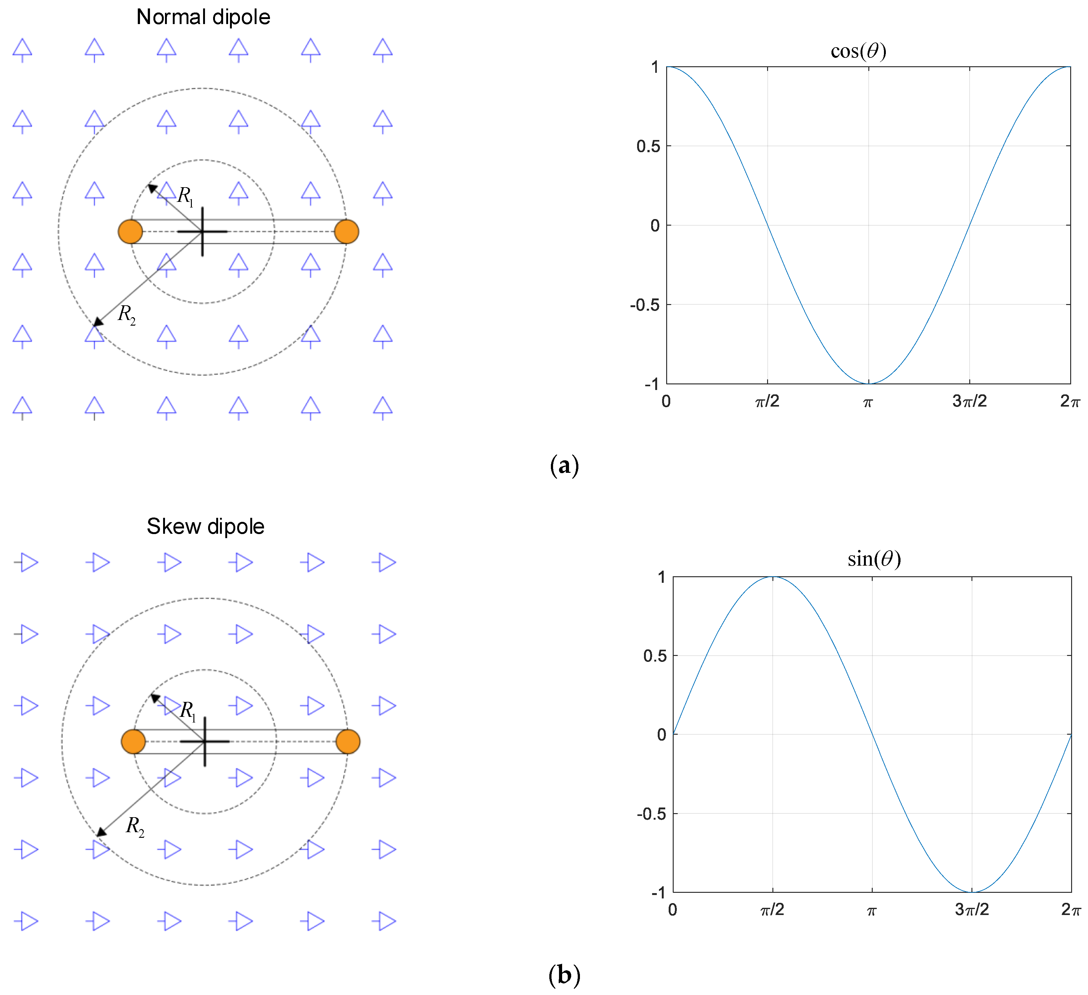
From the abovementioned principle, measuring the intensity of the magnetic field using a rotating coil technique, one can measure the signal as a sinusoidal waveform as shown in Figure 2 below. It is a simulation of the flux obtained by measuring the magnetic field in the vertical axis (normal dipole) and horizontal axis (skew dipole).
From Equation (1) and Figure 2, the electromotive force obtained from the search coil can be measured as in Equation (5):
V ( t ) = d d t { n = 1 N L R 2 n R 1 n n R 0 n 1 [ B n ( R 0 ) cos n θ A n ( R 0 ) sin n θ ] } ,
V ( t ) = n = 1 N L ω R 2 n R 1 n R 0 n 1 [ B n ( R 0 ) sin θ A n ( R 0 ) cos n θ ] ,
where θ = ω t + δ .
From Equation (6), it can be noticed that the electromotive force obtained from the search coil directly varies with the rotating speed of the coil. Magnetic field measurements with this technique can result in an approximately 0.1% error in rotation. Therefore, it is necessary to have a constant speed control system for the search coil, because the electromotive force varies directly with the speed used in the rotation. This study used a Direct Current (DC) motor to drive the packed coil into the cylinder rod and used a closed-loop control system with the PI controller. A block diagram of the speed control system of the rotating coil is shown in Figure 3, and the PI controller is shown in Equation (7):
C o n t r o l l e r = K p + K i s ,
where K p is the proportional control, and K i is the integral control.

2.1. Mathematical Model of the DC Motor

This study used a DC motor to rotate a cylinder rod which contained a coil to the control speed at a range of 60–120 rpm. The working principle of the DC motor is that it changes electrical energy into mechanical force that can be controlled by armature control using the adjustment of voltage for armature circuit to control the speed of rotation. The control will modify the voltage given to the armature circuit starting from the motor torque control equation as shown in Equation (8):
J A ω ˙ = b ω + K T i a ,
where J A is the armature inertial (kg⋅m2), ω is the angular velocity of the rotating coil (rad/s), b is the coefficient of viscous friction (N⋅m/(rad/s)), K T is the motor torque constant (N⋅m/A), and i a is the armature current (A).
The electromotive force equation is as shown in Equation (9):
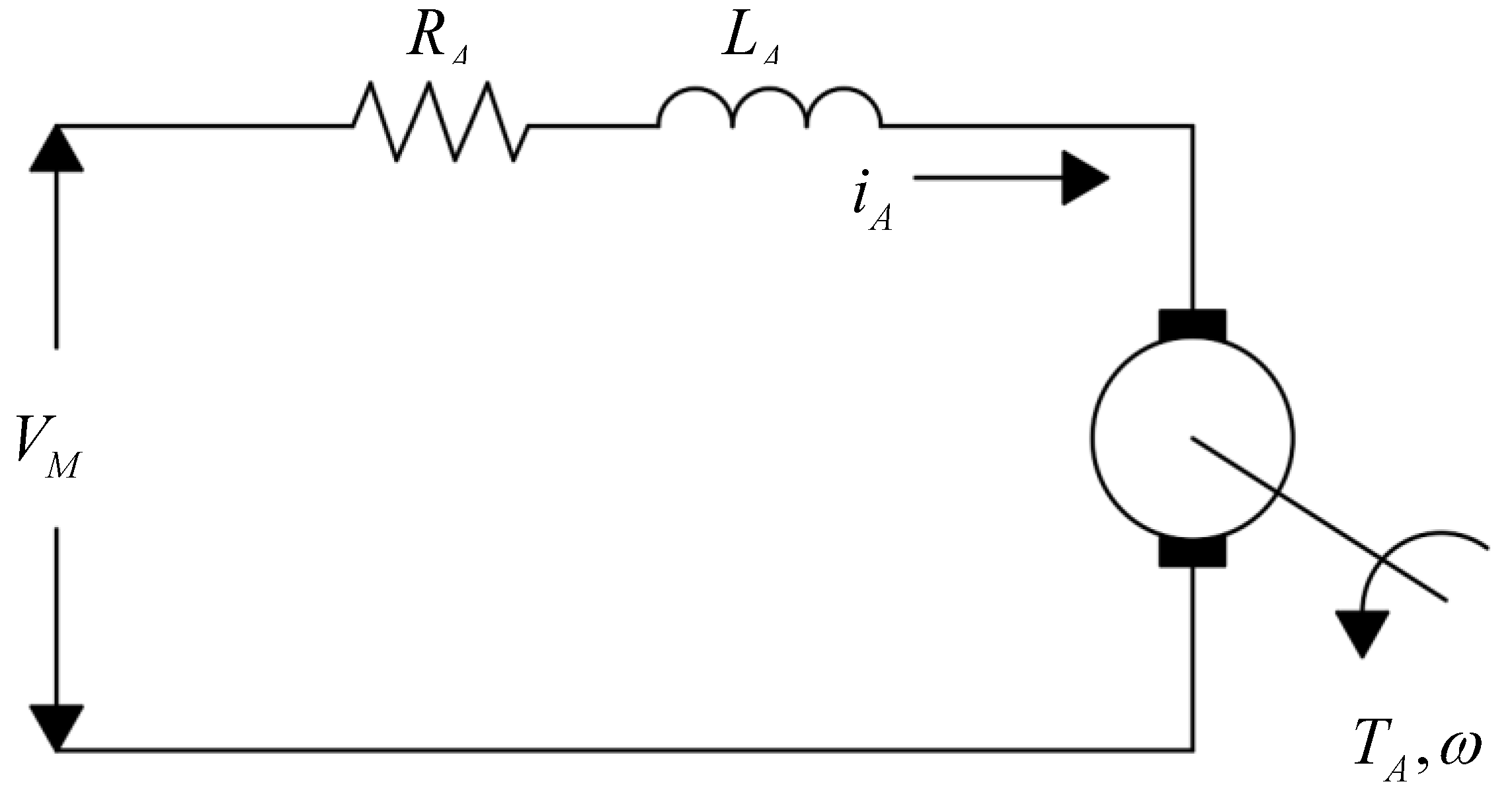
V M V b = L A d i d t + R A i A ,
where V b = K B ω , K B is the motor voltage constant (V/(rad/s)), V M is the electromotive force of the motor (V), L A is the armature inductance (H), and R A is the armature resistance (Ω).
The diagram of the armature cycle is shown in Figure 4.
Equations (7) and (8) can be written as a mathematical equation of the DC motor in a state–space model as follows:
[ ω ˙ i ˙ A ] = [ b J A K T J A K B L A R A L A ] [ ω i A ] + [ 0 1 L A ] V M ,
In practice, the variables of some DC motors cannot be measured directly without knowing the value of such variables used in the controller’s design. Identification of the DC motor uses a function in the MATLAB–Simulink program (MATLAB 2020b License No.199467, Suranaree University of Technology), in relation to parameter estimation. The procedure for estimating the value of variables of a DC motor is the response value of the voltage and the speed of rotation of the motor which is obtained from the experiments taken as input data ( V M ) and output data ( ω ) in the MATLAB program for comparing the output ( ω ^ ) of mathematical model. Then, the PI controller is designed using the MATLAB–Simulink program for signal constraints. By setting the percentage overshoot value, rise time, and steady state, a controller can now work within the required scope.

2.2. Mathematical Model of a Rotating Coil Rod

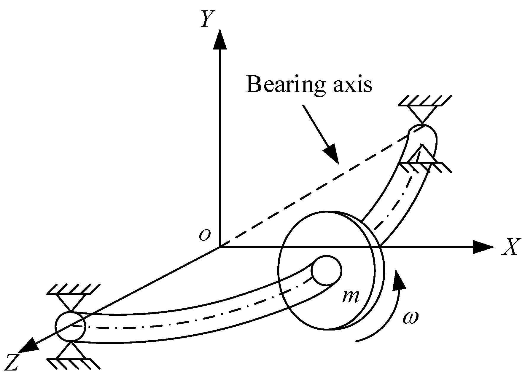
The structure of the cylinder rod that contained the search coil was made from G10 material (composite material) [26]. This has many advantages: (a) it does not affect the measurement of the electromagnetic field; (b) it is designed to look like a round shaft, has a diameter of 80 mm, length of 500 mm, can support the weight of 2 bearings, around itself at a constant speed, and can estimate the mathematical model such like that of the Jeffcott rotor model as shown in Figure 5.
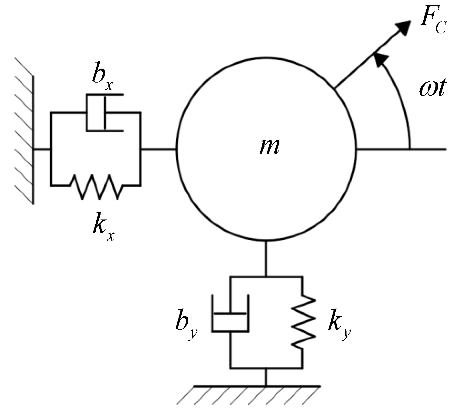
From Jeffcott’s model, the problem of the cylinder rod’s movement results from the weight of the whirling, which causes an unbalance in its rotation. The imbalance in the rotation of the cylinder rod affects the harmonic force, which is a forced tremor. The motion model, due to the fact of an imbalanced rotating coil, is shown in Figure 6.
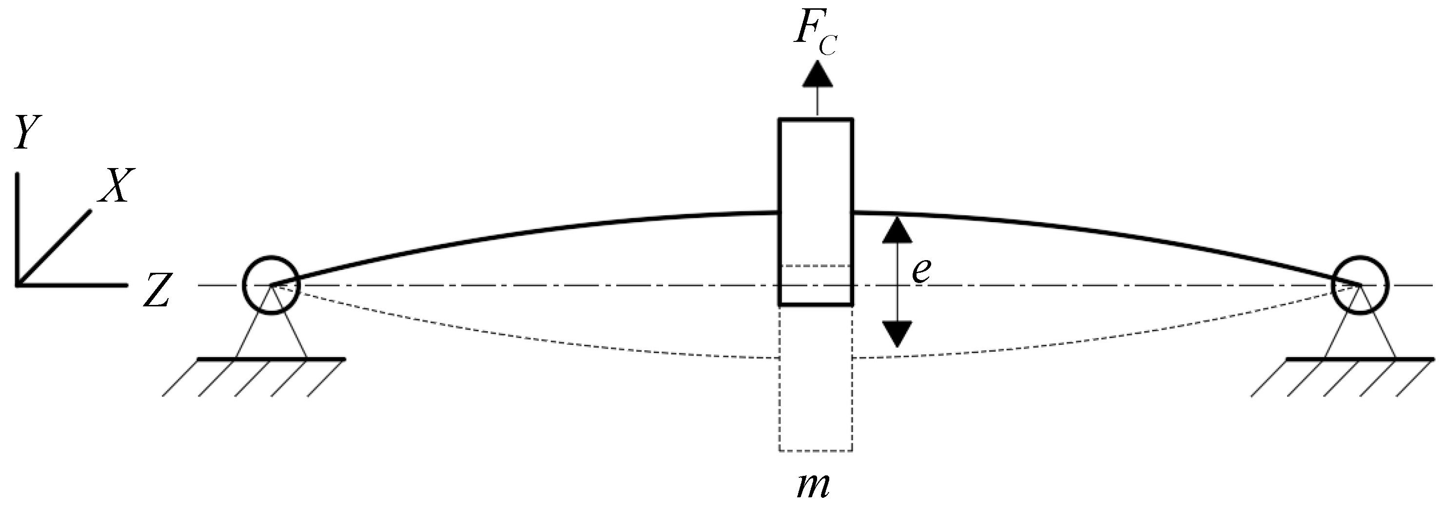
Figure 6 displays a model of rotational unbalance, where m is shaft weight and F C is forced unbalanced as shown in Equation (11).
F C = m e ω 2 ,
where e is the whirling of shaft ( m ) and m e is the mass with distance causing the unbalancing of rotation and affecting the whirling of the cylinder rod as shown in Figure 7.
Figure 7 shows the whirling of the shaft due to the presence of weight that may cause movement in various ways around the rotational axis in a circle or an ellipse as shown in Figure 8.
In this research, the whirling of the cylinder rod is studied and analyzed by considering the bearing that supports it as a strong object, while the cylinder rod supports it as a flexible object. In practice, two axes were considered: vertical axis and horizontal axis. The equation of movement at the vertical axis and horizontal axis is shown in Equations (12) and (13).
Movement of vertical axis equation, y:
m x ¨ + c y y ˙ + k y y = m e ω 2 sin ω t ,
where m is the mass (kg), c y is the damping coefficient in the y direction (N⋅s/m), and k y is stiffness in the y direction (N/m).
Movement of the horizontal axis equation, x:
m x ¨ + c x x ˙ + k x x = m e ω 2 cos ω t ,
where c x is the damping coefficient in the x direction (N⋅s/m), and k x is stiffness in x direction (N/m).
The amplitude of the centrifugal force exerted by the unbalanced rotating of the cylinder rod was m e ω 2 . The amplitude of force directly converted with the rotation ( ω ) of the cylinder rod, where y and x were amplitudes at vertical and horizontal. The whirling distances at the vertical and horizontal are shown in Equations (14) and (15).
Vertical amplitude, y:
y = m e ω 2 ( k y m ω 2 ) 2 + ( c y ω ) ,
Horizontal amplitude, x:
x = m e ω 2 ( k x m ω 2 ) 2 + ( c x ω ) ,
From Equations (13) and (14), the vertical and horizontal whirling distances can be analyzed and calculated using the equation of movement of cylinder rod orbit while rotating. This indicates that the movement is in ideal, horizontal ellipse, and vertical ellipse feature, etc.

3. Experimental Setup

In this research, equipment for the experiment was set-up in two parts: part 1—assembling the magnetic measurement equipment setup; part 2—installation of the whirling measurement equipment for the rotating coil.

3.1. A Magnetic Measurement Equipment Setup

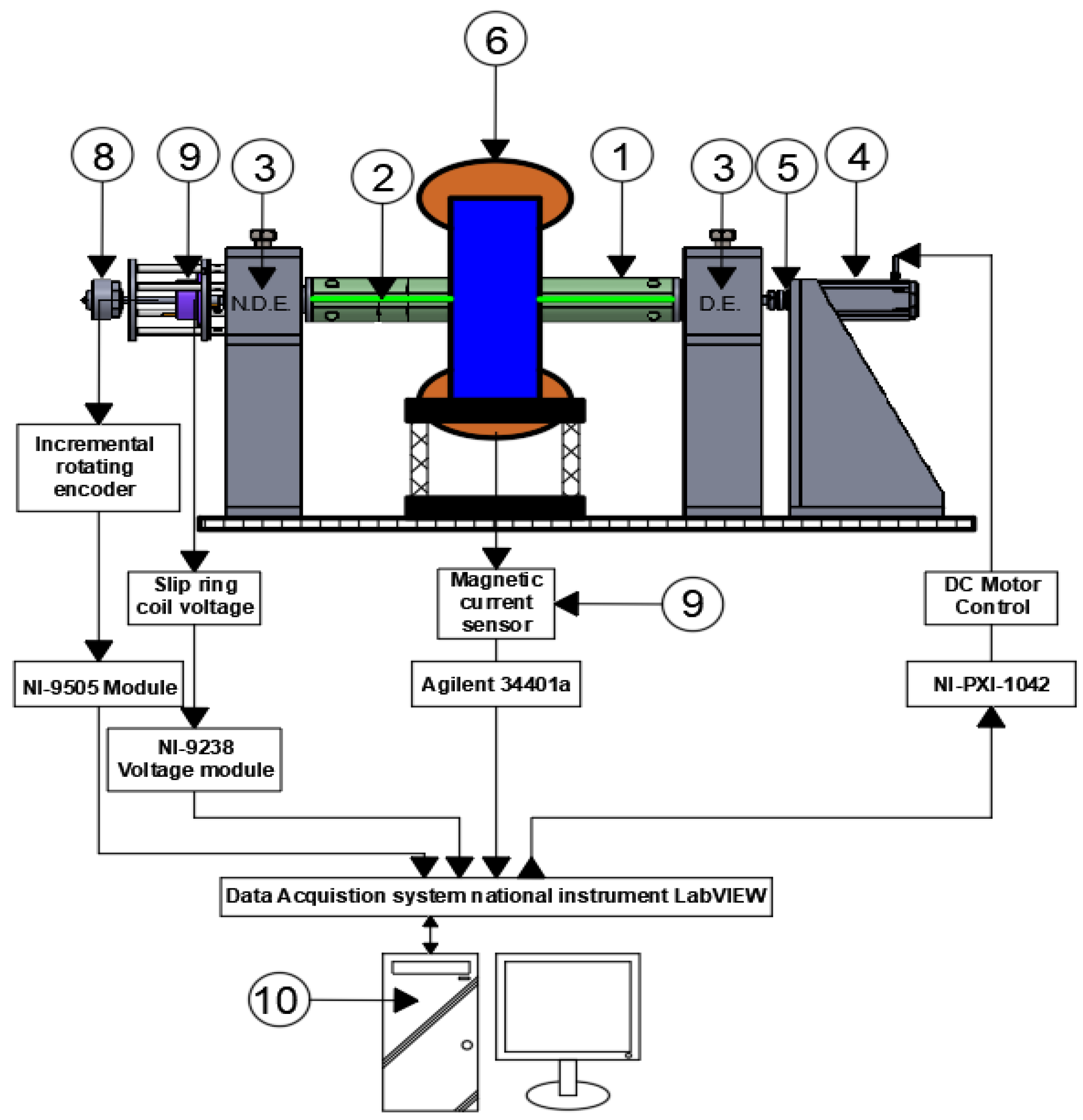
Figure 9 displays a magnetic field measuring device with two important components: (a) A rotating coil drive that consists of a cylinder rod for packing coils made from G10 material (diameter 63.5 mm, length 470 mm); (1) a Printed Circuit Board(PCB) board with a search coil inside (width 53 mm, length 430 mm); (2) multi-row angular contact ball bearings placed on a base made of aluminum as a support point for the cylinder rod; (3) a DC motor worm gear (100 W, 24 V, with a maximum current 4.6 A for driving the rotating coil); (4) flexible coupling for conveying power from the motor to the rotating coils (5). (b) Measurement and data collection, which consisted of electromagnet dipole magnets sized 0.4 Tesla (6), magnetic current sensor and Agilent 3440a for reading the current supplied to the electromagnet (7), slip ring coil voltage and NI-9238 voltage module for measuring the electromotive force obtained by measuring the magnetic field (8), incremental rotating encoder and NI-9505 Module for measuring the speed and angular position of the rotating coil (9), and a computer for recording the results of the experiment with the LabVIEW 2017 program (10).

3.2. A Whirling Measurement Equipment of the Rotating Coil

The equipment in Figure 10 was installed to measure the whirling of the coil containing important equipment including the eddy current probe sensor, which had a measurement range of 4 mm, resolution of 4 micrometers, and a set of amplifier outputs of 0–10 volts. It measures the whirling in all three positions: drive end (DE), center (C), non-driver end (NDE) by measuring two points each in the vertical axis and horizontal axis. The sensor for measuring the rotational phase (photo microsensor) response frequency 1 kHz. Connect via NI-PXI-6259 module and NI-PXI-1071 with the LabVIEW 2017 program (LabVIEW Professional development system version, License No. M76X33883, Synchrotron Light Research Institute (Public Organization), Nakhon Ratchasima, Thailand).

4. Results and Discussion

Once the experimental setup for measuring and storing data was completed, this research was divided into four experiments.

4.1. Estimation of the DC Motor’s Mathematical Model

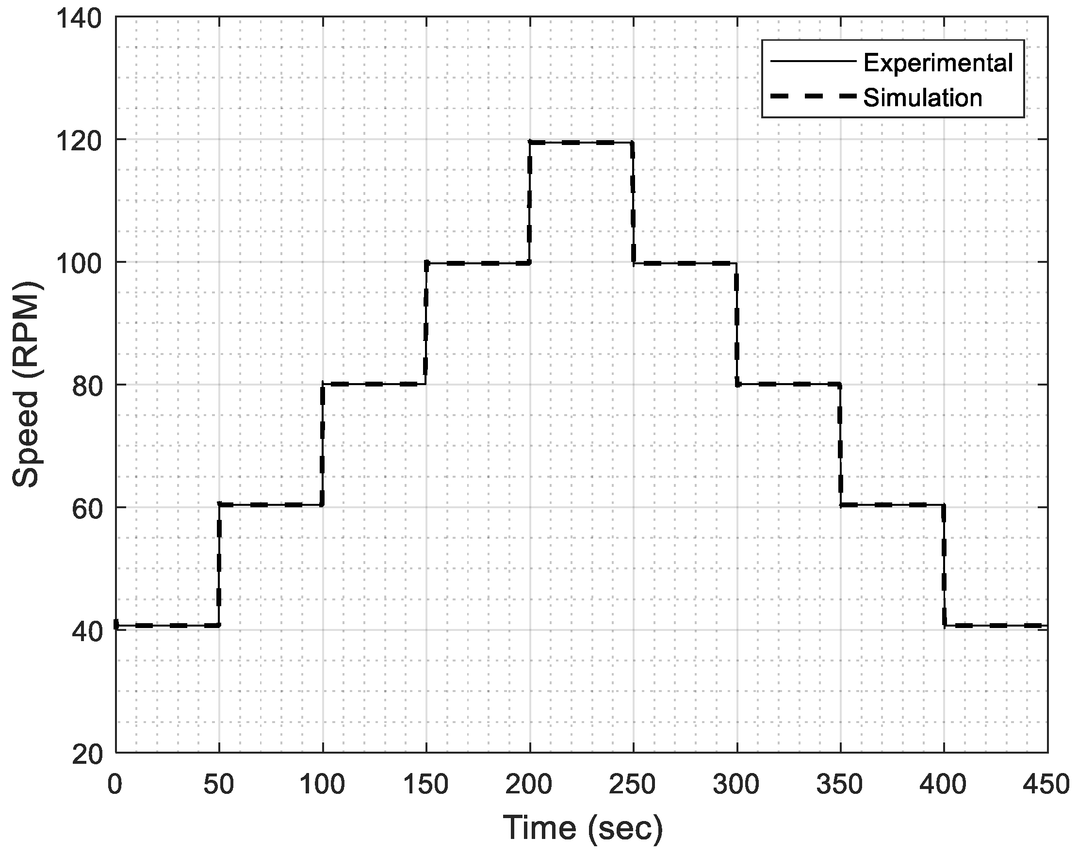
This experiment collected input data that were input voltages and output data that included the speed of the motor tested in the range 40–120 rpm. We used the obtained data to identify the mathematical model of a DC motor by estimating variables with the MATLAB–Simulink program for the function of parameter estimation. Then, we compared the results from the mathematical model with the experimental results as shown in Figure 11. There was an error between the mathematical model and the experimental results of 2.27% as shown.
The values of the variables obtained by identifying the DC motor with the parameter estimation function are shown in Table 1.

4.2. Test Results of the Speed Control System with a PI Controller

In this experiment, the scope of the control variables was defined for designing to achieve the desired response. The specifications of a speed control system with a PI controller are percent overshoot (not more than 5%), rise time (less than 2 s), settling time (less than 5 s), and steady-state error (less than 2%). The results from optimization with MATLAB–Simulink in relation to signal constrain function used to find the optimization PI controller are shown as Table 2.
From Table 2, take the value of the P and the I controller to test the speed control system of a DC motor if they are as designed at 60, 90, and 120 rpm. The step response of closed-loop speed-control system with PI controller are shown in Figure 12.
Figure 12 illustrates that the speed control system can work under the conditions specified for each speed. It was found that the highest whirling speed was 5.527 percent at a speed of 60 rpm and the lowest whirling speed was 2.79 percent at a speed of 120 rpm as shown in Table 3.

4.3. The Results of Dipole Magnet Field Measurement (Skew Dipole Magnets)

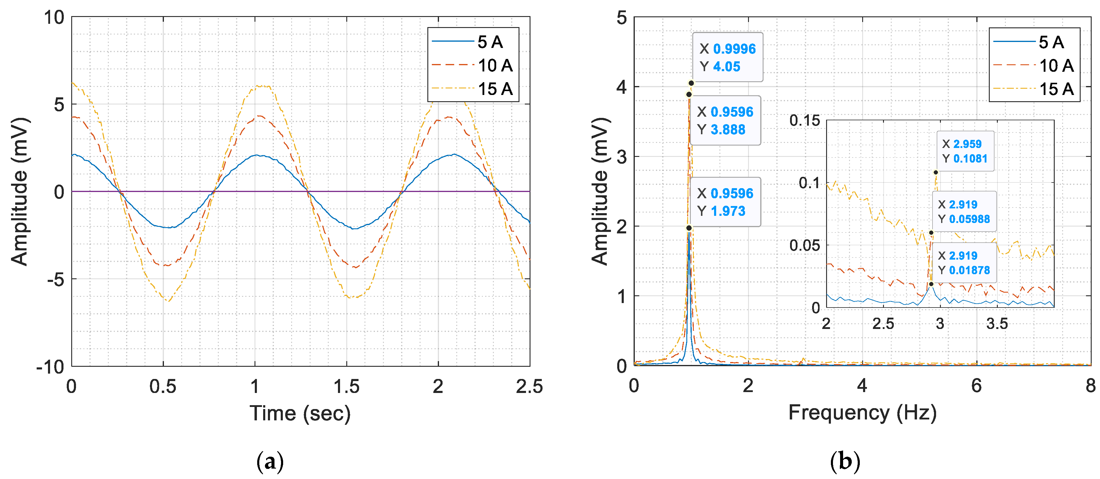
In this section, the voltage supplied to the electromagnet coil (solenoid) was constant at 2 volts, and the current supplied to the magnetic coils were 5, 10, and 15 A. The experiment presented in Section 4.3. was divided into three sub-experiments as shown in Figure 13, Figure 14 and Figure 15.
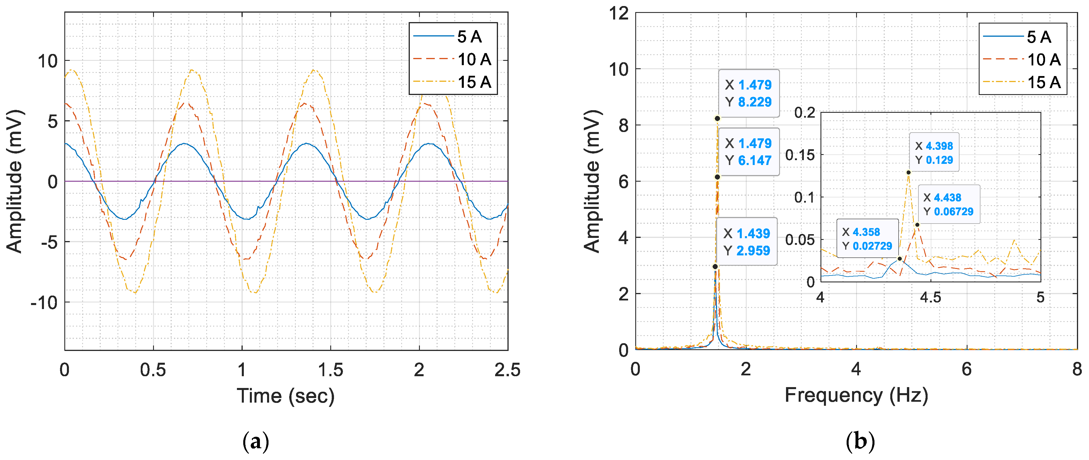
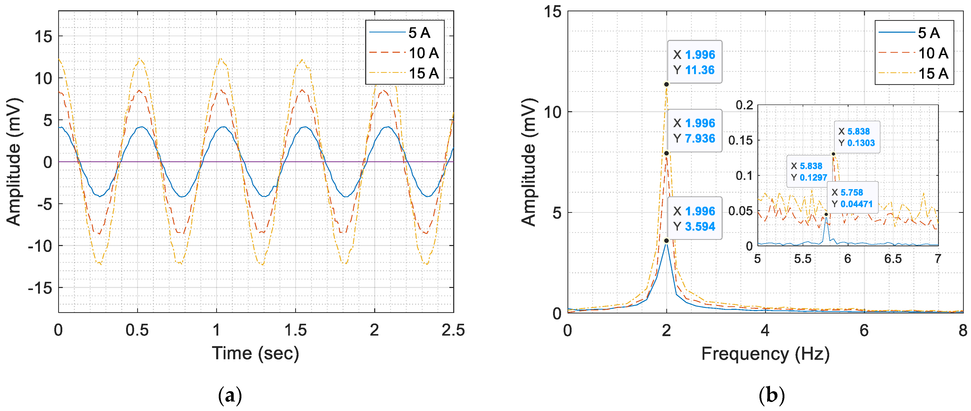
From the experimental results shown in Figure 13, Figure 14 and Figure 15, it was found that when the rotational speed was higher, the electromotive force was higher as well and had the highest electromotive force at a rotational speed ω of 120 rpm. In addition, increasing the electric current to the dipole magnet enhanced the electromotive force too, and the magnetic field value was the highest at 15 amp. The results from the experiment in Section 4.2. reveal that the controller design had a higher number of errors than that of the magnetic measurement system. It affected the magnitude of the electromotive force changes with the speed of rotation. This can be observed from the highest and lowest values as shown in Figure 14a, Figure 15a, and Figure 16a in each movement of the coil around the magnetic cavity. Then, the signal in the form of a spectrum was analyzed as shown in Figure 14b, Figure 15b, and Figure 16b with Equation (16).
O r d e r = C P M R P M ,
From Equation (16), when comparing the induced electromotive force signal obtained from the measurement (CPM, cycles per minute) with the speed of the rotating coil (RPM, revolutions per minute), other harmonic signals are characterized. This research considers this in four orders. It was found that at every rotation speed, a third harmonic (Order 3) occurred. It may cause an error in controlling the speed of a rotating coil which is not within the specified limit or mechanical looseness according to ISO10816-1 in assembly of measuring instruments. This affects the electromagnetic field’s measurement. The measured value is shown in Table 4.

4.4. Measuring the Orbit, the Whirling of the Rotating Coil

In this section, the whirling distance of the coil while rotating around the center of rotation is measured. There are three measuring points along the length including the driver end (DE) point, center point, and non-driver end (NDE) point. The experiment in Section 4.4 was divided into three sub-experiments as shown in Figure 16, Figure 17 and Figure 18.
From the experiment shown in Figure 16, Figure 17 and Figure 18 of each speed in rotation of the coil, they revealed that they all had similar orbital characteristics. That is because the shaft rotated at a low speed (low-speed machine); thus, the motion’s orbit changed little and maximum distance between maximum and minimum movement of the coil at different positions in the vertical and horizontal axis as shown in Table 5. The motion’s behavior moved away from the center of the rotation. At the DE position, the coil rose up; at the C position, it moved to the right; at the NDE position, it moved to the left.
From the experimental orbital motion of the magnetic field measurement using the rotating coil technique, it was found that the movement of the cylinder rods was caused by rotational unbalance, and misalignment and mechanical looseness did not affect the measurement of the dipole magnetic field. This is because the direction of the magnetic field was either a direct line or a single direction in both a skew dipole and a normal dipole.

5. Conclusions

This research displays the measurements and analyses of the results of an instrument for measuring the magnetic field of dipole magnets, such as the normal dipole and the skew dipole, using a rotating coil technique. Via the results of the experiment, the speed control system revealed that the errors in the steady-state response did affect the measured amplitude of the dipole magnetic field, and the orbit of the unbalanced motion was not affected, because the amplitude of the dipole magnetic field was not dependent on the position of the search coil. Although the orbit of the unbalanced motion, misalignment, and mechanical looseness did not affect the measurement of dipole magnetic field using the rotating coil technique, the reason that the designed controller was unable to work under the specified conditions for magnetic field measurement was that it demands only a 0.1% error in rotation. This might result from unchecked assembly without mechanical test such as the natural frequency of the system, imbalance, misalignment, shaft coupling, bearing friction, and mechanical looseness. These factors can trigger a serious impact on the instruments use for measuring quadrupole magnets or sextupole magnets which require higher measurement accuracy than a dipole magnet.

Author Contributions

Conceptualization, S.O. and J.S.; methodology and validation, S.O., P.S. and J.S.; experimental setup and data collection, W.T., C.P. and S.O.; formal analysis and investigation, S.O. and J.S.; writing-original draft preparation, S.O.; writing-review and editing, S.O., and J.S. All authors have read and agreed to the published version of the manuscript.

Funding

This research was funded by Synchrotron Light Research Institute (Public Organization) grant number 03/2558.

Acknowledgments

The authors would like to express sincere gratitude to Suranaree University of Technology (SUT) and Synchrotron Light Research Institute (Public Organization) for their generous support.

Conflicts of Interest

The authors declare no conflict of interest.

References

  1. Kang, W.; Deng, C.D.; Li, Q.; Li, L.; Chen, W.; Yin, B.G.; Zhou, J.X.; Sun, X.J.; Chen, F.S.; Shi, C.T. Research and Development of the AC Magnets for CSNS/RCS. IEEE Trans. Appl. Supercond. 2012, 22, 4001204. [Google Scholar] [CrossRef]
  2. Sunwong, P.; Boonwanna, S.; Chaichuay, P.; Klysubun, P.; Kwankasem, A.; Preecha, C. Design and fabrication of a combined function magnet prototype for Siam photon source. In Proceedings of the 9th international particle accelerator conference (IPAC2018), Vancouver, BC, Canada, 29 April–4 May 2018. [Google Scholar] [CrossRef]
  3. Petrone, C.; Nugteren, J.V.; Bajas, H.; Bottura, L.; Kirby, G.; Rossi, L.; Russenschuck, S. Measurement and Analysis of the Dynamic Effects in an HTS Dipole Magnet. IEEE Trans. Appl. Supercond. 2018, 28, 1–4. [Google Scholar] [CrossRef]
  4. Li, L.; Li, Y.J.; Ni, G.L.; Chen, W.; Sun, X.J. Rotating coil magnetic measurement system and measurement results of quadrupole prototype for BEPCII storage ring. In Proceedings of the 2005 Particle Accelerator Conference (PAC), Knoxville, TN, USA, 16–20 May 2005; ISBN 0-7803-8859-3. [Google Scholar]
  5. Peng, Q.; Yin, B.; Zhou, J.; Wu, Y.; Brueck, H.; Stolper, M.; Shi, W. Harmonic coil design, Fabrication and commissioning for European XFEL linear accelerator superconducting magnets field measurement. IEEE Trans. Appl. Supercond. 2010, 20, 2015–2018. [Google Scholar] [CrossRef]
  6. Rogacki, P.; Fiscarelli, L.; Russenschuck, S.; Hameyer, K. Development of a rotating-coil scanner for superconducting accelerator magnets. J. Sens. Sens. Syst. 2020, 9, 99–107. [Google Scholar] [CrossRef]
  7. Arpaia, P.; Bottura, L.; Cimmino, P.; Giloteaux, D.; Masi, A.; Perez, J.G.; Spiezia, G.; Walckiers, L. A fast-digital integrator for magnetic field measurements at Cern. In Proceedings of the 2006 IEEE Instrumentation and Measurement Technology Conference, Sorrento, Italy, 24–27 April 2006; ISBN 0-7803-9359-7. [Google Scholar]
  8. Li, L.; Kang, W.; Wang, Z.; Li, S.; Zhang, S.; Yin, B.; Zhou, J.; Shi, C. Magnetic Field Measurement of the Quadrupole and sextupole magnets for HLS-II storage ring. IEEE Trans. Appl. Supercond. 2014, 24, 1–4. [Google Scholar] [CrossRef]
  9. DiMarco, J.; Chlachidze, G.; Makulski, G.; Makulski, A.; Orris, D.; Tartaglia, M.; Tompkins, J.C.; Velev, G.V.; Wang, X. Application of PCB and FDM technologies to magnetic measurement probe system development. IEEE Trans. Appl. Supercond. 2012, 23, 9000505. [Google Scholar] [CrossRef]
  10. Gunter, E. Understanding amplitude and phase in rotating machinery. In Proceedings of the Vibration Institute 33 Annual Meeting, Harrisburg, PA, USA, 23–27 June 2009. [Google Scholar]
  11. Xul, J.; Zheng, X.; Zhang, J.; Liu, X. Vibration characteristics of unbalance response for motorized spindle system. Procedia Eng. 2017, 174, 331–340. [Google Scholar] [CrossRef]
  12. Yamamoto, G.K.; Costa, C.; Sousa, J.S.S. A smart experimental setup for vibration measurement and imbalance fault detection in rotating machinery. Case Stud. Mech. Syst. Signal Process. 2016, 4, 8–18. [Google Scholar] [CrossRef] [Green Version]
  13. Verma, A.K.; Sarangi, S.; Kolekar, M.K. Experimental investigation of misalignment effects on rotor shaft vibration and on stator current signature. J. Fail. Anal. Preven. 2014, 14, 125–138. [Google Scholar] [CrossRef]
  14. Hariharan, V.; Srinivasan, P.S.S. Vibration analysis of misaligned shaft-ball bearing system. Indian J. Sci. Technol. 2009, 2, 45–50. [Google Scholar] [CrossRef]
  15. Kumar, P.; Prabhat, P.K.; Kumar, M.; Choudhary, S.D. Speed control of dc motor using PID smart controller. Int. J. Eng. Res. 2014, 5, 1044–1053. [Google Scholar]
  16. Ni, S.A.; Mathew, L.; Chatterji, S. Comparative analysis of speed control of dc motor using AI technique. Int. J. Eng. Res. Appl. 2013, 3, 1137–1146. [Google Scholar]
  17. Othman, K.A.; Kamal, M.M.; Mamat, N.; Yati, N. System identification of discrete model for DC motor positioning. In Proceedings of the 8th WSEAS International Conference on Circuits, systems, electronics, control & signal processing (CSECS), Puerto De La Cruz, Canary Islands, Spain, 14–16 December 2009; pp. 212–216, ISBN 978-960-474-139-7. [Google Scholar]
  18. Tang, W.J.; Liu, Z.T.; Wnag, Q. DC motor speed control based on system identification and PID auto tuning. In Proceedings of the 36th Chinese Control Conference (CCC), Dalian, China, 26–28 July 2017; ISBN 978-988-15639-3-4. [Google Scholar]
  19. Arpaia, P.; Buzio, M.; Golluccio, G.; Walckiers, L. In situ calibration of rotating sensor coils for magnet testing. Rev. Sci. Instrum. 2012, 83, 013306. [Google Scholar] [CrossRef] [PubMed] [Green Version]
  20. Arpaia, P.; Buzio, M.; Köster, O.; Russenschuck, S.; Severino, G. Rotating-coil calibration in a reference quadrupole, considering roll-angle misalignment and higher-order harmonics. Measurement 2016, 87, 74–82. [Google Scholar] [CrossRef] [Green Version]
  21. Arpaia, P.; Bottura, L.; Fiscarelli, L.; Walckiers, L. Performance of a fast-digital integrator in on-file magnetic measurements for particle accelerators. Rev. Sci. Instrum. 2012, 83, 024702. [Google Scholar] [CrossRef] [PubMed] [Green Version]
  22. Arpaia, P.; Buzio, M.; Golluccio, G.; Walckiers, L. A polyvalent harmonic coil testing method for small-aperture magnets. Rev. Sci. Instrum. 2012, 83, 085116. [Google Scholar] [CrossRef] [PubMed]
  23. Zhang, H.X.; Zhou, H.; Guo, X.P.; Yan, Y. Rotor Fault Diagnosis and Simulation Based on LabVIEW. Res. J. Appl. Sci. 2013, 19, 3670–3674. [Google Scholar] [CrossRef]
  24. Costa, C.D.; Gama, R.S.D.; Nascimento, C.E.; Brandao, I.M.; Medeiros, E.C.D.; Mathias, M.H. Orbit analysis for imbalance fault detection in rotating machinery. J. Electr. Electron. Eng. 2018, 13, 43–45. [Google Scholar]
  25. Monte, M.; Verbelen, F.; Vervisch, B. The use of orbitals and full spectra to identify misalignment. In Structural Health Monitoring; Springer: Cham, Switzerland, 2014; Volume 5, pp. 215–222. ISBN 978-3-319-04570-2. [Google Scholar]
  26. Professional Plastics. Available online: https://professionalplastics.com/G-10FR4ROD (accessed on 12 November 2020).
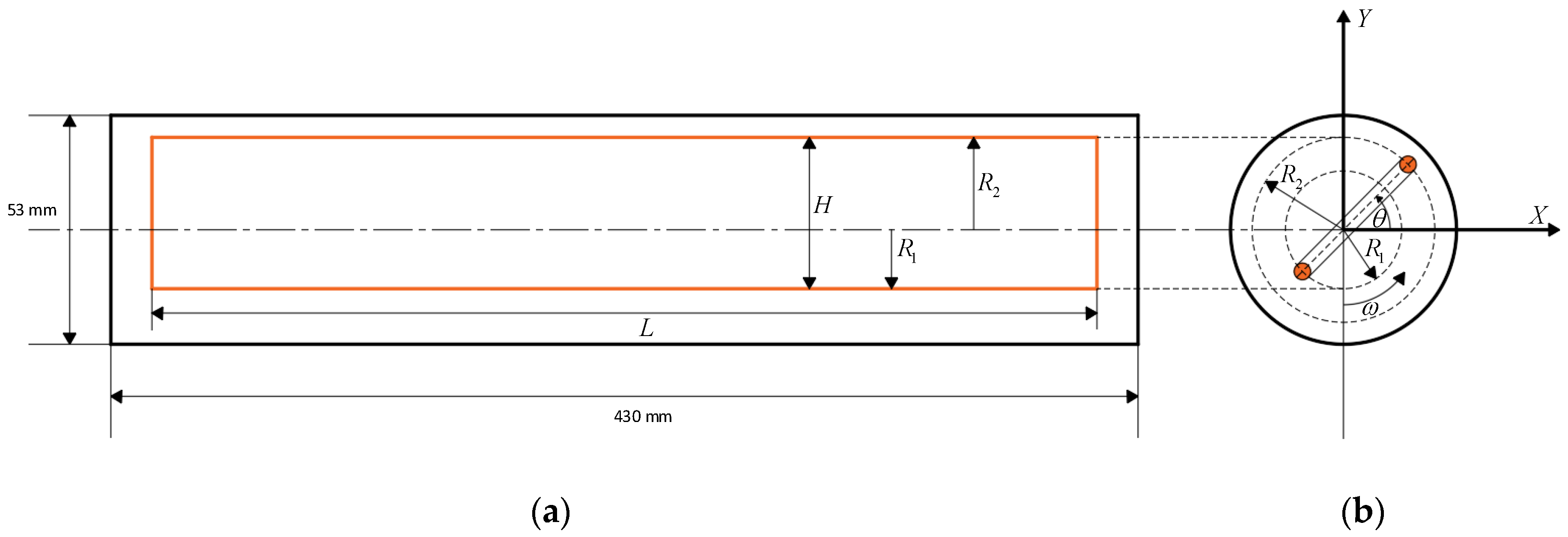
Figure 1. Rotating coil: (a) search coil; (b) orbit of a dipole magnetic field.
Applsci 10 08454 g001
Figure 2. (a) Normal dipole signal; (b) skew dipole signal.
Applsci 10 08454 g002
Figure 3. Block diagram of the DC motor speed control system.
Applsci 10 08454 g003
Figure 4. Diagram of the armature cycle of a DC motor.
Applsci 10 08454 g004
Figure 5. Jeffcott rotor model.
Applsci 10 08454 g005
Figure 6. Model with dampers and springs.
Applsci 10 08454 g006
Figure 7. Model of a rotating coil.
Applsci 10 08454 g007
Figure 8. Shaft orbit: (a) circular motion; (b) elliptical motion.
Applsci 10 08454 g008
Figure 9. Magnetic measurement equipment set up using a rotating coil.
Applsci 10 08454 g009
Figure 10. The installation of the measuring shaft whirling unit.
Applsci 10 08454 g010
Figure 11. The results of the comparison between the mathematical model and the experimental results of the DC motor.
Applsci 10 08454 g011
Figure 12. The speed response with a PI controller: (a) 60 RPM; (b) 90 RPM; (c) 120 RPM.
Applsci 10 08454 g012
Figure 13. This figure shows the speed of the rotating coil 60 rpm (1 Hz): (a) the electromotive force of the magnetic field at 60 rpm; (b) the spectrum of the electromotive force of the magnetic field.
Applsci 10 08454 g013
Figure 14. This figure shows the speed of the rotating coil at 90 rpm (1.5 Hz): (a) the electromotive force of the magnetic field at 90 rpm; (b) the spectrum of the electromotive force of the magnetic field.
Applsci 10 08454 g014
Figure 15. This figure shows the speed of the rotating coil 120 rpm (2 Hz): (a) the electromotive force of the magnetic field at 120 rpm; (b) the spectrum of the electromotive force of the magnetic field.
Applsci 10 08454 g015
Figure 16. The comparison of the movement characters of the rotating coil at 60 RPM: (a) shaft orbit at DE side; (b) shaft orbit at center; (c) shaft orbit at NDE side.
Applsci 10 08454 g016
Figure 17. The comparison of the movement characters of the rotating coil at 90 RPM: (a) shaft orbit at the DE side; (b) shaft orbit at the center; (c) shaft orbit at the NDE side.
Applsci 10 08454 g017
Figure 18. The comparison of the movement characters of the rotating coil at 120 RPM: (a) shaft orbit at the DE side; (b) shaft orbit at the center; (c) the shaft orbit at the NDE side.
Applsci 10 08454 g018
Table 1. Values of the DC motor’s variables.
ParameterValue
RA3.2715
LA2.0487 H
JA14.7729 kg⋅m2
KT9.6361 × 10−3 N⋅m/A
KB7.0103 × 10−2 kg⋅m2
b5.8634 N⋅m/rad/s
Table 2. The value of the PI controller.
ControllerKpKi
Gain0.006970.03100
Table 3. Speed of rotating coil at a steady-state response.
Motor Speed Control
Speed (RPM)6090120
Minimum value56.9785.73116.67
Maximum value63.1993.46122.22
% Error5.534.402.79
Table 4. The electromotive force obtained from change in speed and dipole magnet current.
Speed (RPM)The Current Supplied to the Magnetic Coil
Current 5 ACurrent 10 ACurrent 15 A
1X2X3X4X1X2X3X4X1X2X3X4X
601.973-0.0187-2.959-0.0273-3.594-0.0447-
903.888-0.0589-6.147-0.0672-7.936-0.1297-
1204.050-0.1081-8.229-0.1290-11.360-0.1303-
Table 5. The movement of the coil at different positions in the vertical and horizontal axis.
Speed
(RPM)
Driver End (DE)CenterNon-Driver End (NDE)
Vertical (mm)Horizontal (mm)Vertical (mm)Horizontal (mm)Vertical (mm)Horizontal (mm)
600.451020.411820.336400.360450.675480.71642
900.436180.416100.340740.357400.684220.71754
1200.437470.412290.340250.361740.683250.71866
Publisher’s Note: MDPI stays neutral with regard to jurisdictional claims in published maps and institutional affiliations.