1. Introduction
In the past decade, intelligent control has brought a huge change to our daily lives. Image processing and robot arms play important roles in many intelligent control designs. There are a lot of applications of image processing and robot arms, such as medical surgery, automatic manufacturing, home care, food processing, etc. According to target positions, robot movement needs to be designed for high precision and stability in the control process. As robotic technologies improve in a variety of ways, many difficult or time-consuming tasks can be performed by robots with high precision and recognition capability [
1,
2,
3,
4]. Nowadays, global industry is moving to Industry 4.0, which holds the promise of increased flexibility in manufacturing, better quality, and improved productivity [
5]. This study is mainly focused on improving the efficiency of smartphone testing procedures so that the proposed system can replace the labor force in routine smartphone tests. Intelligent robots have become a key part in many applications [
6,
7,
8,
9,
10]; they can provide health care, home service, entertainment, industrial automation, etc. Intelligent robots are used in many research fields, such as for path planning, obstacle avoidance, simultaneous localization and mapping, visual servoing control and image processing [
11,
12,
13]. Expert knowledge has been integrated into the robot system design that makes interactions between human and robot harmonious. The objective of this study is to replace manual smartphone testing with automatic robot arm adapted to the Chinese character environment. The proposed control scheme can automatically test a smartphone by the use of a robotic system. With support vector machine (SVM) [
14], a histogram of oriented gradients (HOG) [
15], neural networks, and fuzzy theory, complex computation [
16] can be reduced in the control process.
Boser, B.E. et al. [
17] improved SVMs and proposed a method to generate nonlinear classifiers using the kernel trick to the maximum margin hyperplane. With HOG describing local object appearance and shape within an image by the distribution of intensity gradients or edge directions, the SVM was able to classify data more successfully. The method utilized for coordinate conversion so that the robot arm can be driven to target positions is the Denavit–Hartenberg parameters (D-H) model [
18]. In our study, the target positions are on the smartphone, which are the desired buttons to be pressed. Image processing and pattern recognition techniques are needed to locate the target button position. The webcam captures an image using Red-Green-Blue (RGB) color, which is easily affected by lightness. Hue, saturation and lightness (HSL) color space is usually applied to reduce this effect. The histogram of oriented gradient (HOG) can recognize features of the picture. With HOG describing local object appearance and shape within an image by the distribution of intensity gradients or edge directions, the SVM will be able to classify data more successfully. The SVM-HOG can recognize symbol characters on the screen of the smartphone and ignore the effect of lightness and camera angle. Thus, the HSL transformation process can be omitted, which reduces the calculation burden. In image processing, we do not have to convert the image to HSL color space or another form of binary image. This is an advantage of SVM-HOG in system processes. In optical character recognition, the accuracy of Asian characters documents is usually lower than that for English documents [
19,
20,
21]. While using optical character recognition (OCR) [
22,
23] on Chinese characters and Chinese Mandarin phonetic symbol recognition, it is hard to use OCR to compare symbol characters and pictures because the system is based on an English environment. Besides, the performance of OCR is low on symbol recognition. This study replaces OCR character recognition by picture comparison similar to car detection and traffic sign detection. In [
24], a supervised learning model called SVM-HOG is used for a car detection methodology in an outdoor environment. In [
25], the authors compare k-Nearest Neighbor (k-NN) and SVM; SVM-HOG is better than k-NN-HOG. With SVM-HOG, we can recognize symbol characters on the screen of the smartphones and ignore the effects of lightness and camera angle. In addition, we need machine vision to check whether the character typed by the robot arm is correct or incorrect. Geometric matching [
26] can help match the picture of a character in a specific area.
Denavit [
27] established four parameters and transformed the matrix of a robot’s coordinates. The robot can be controlled to track an assigned trajectory. J.C. Wang [
28] designed a system of fast inverse kinematics by using a least-squares approximation that can obtain the joint degree faster. We can transform target coordinates to the robot arm’s motor faster by using this method. When the robot arm grabs an object, the magnitude of joint torque can be obtained as in [
29]. In [
30], fuzzy sliding mode control was applied to a two-link robot arm. The control parameters are tuned by fuzzy-neural techniques. The robot arm consists of forward and inverse kinematics algorithm. In general, forward kinematics is set up by a D-H model [
4,
31]. Differential kinematics has been derived to control and change the posture of a robot arm. With the D-H model, we can obtain the kinematics of robot arms easily. In inverse kinematics, the complexity is usually more difficult than in forward kinematics. Therefore, many studies presented inverse kinematics by different systems. The robot system in [
32] is designed to push the buttons of an elevator using the inverse kinematics technique. In [
33], a system solved the inverse kinematics problem that controls the robot arm to lock a screw with the hybrid fuzzy control. These methods are applied to the proposed control design for a smartphone test system.
3. Image Processing
The purpose of this study is to control the robot arm to touch the target position. Although optical character recognition (OCR) can recognize Chinese characters, it does not work with Chinese Mandarin phonetic symbols. Because each symbol is too simple and similar, OCR easily fails to recognize them. In our testing experiments, the recognition rate of OCR is only around 40% to 50%. Here, we chose the SVM classifier with the HOG feature descript to recognize Chinese Mandarin phonetic symbols. The coordinate calculation of symbols by using SVM-HOG is processed on MATLAB; then, coordinate information is sent to LabView which is used on robot arm control. The recognition rate increases to about 70 percent by doing so. Still, we need pattern matching to see if the symbols or characters typed by the robot arm are correct or incorrect. Geometric matching provides pattern matching at different angles; even those that are covered by other patterns. Geometric matching uses National Instruments Vision Assistant (NIVA) to achieve the specified function. The NIVA allows one to easily configure and benchmark a sequence of visual assistant steps. For NIVA environment setup, used for the purpose of acquiring images, the system must have NI image acquisition (IMAQ) hardware with NI-IMAQ 3.0 or later installed for IEEE 1394 Cameras 1.5 or later. The NIVA is installed on the Microsoft Windows operating system. A webcam provides images and then the words and symbols on the smartphone screen are recognized by the proposed process as shown in
Figure 3. The process has three main steps: image preprocessing, image recognition and dictionary check. Dictionary check is also executed through the NIVA on MATLAB. By using the proposed method, the recognition accuracy increases to 90%.
The angle of image captured by the camera is important. We cut an image into small squares to let each symbol appear in a different square. Because of the viewing angle, symbols might not be completed if cut in the traditional way. The traditional way means a picture is cut into several frames of the same size, and each frame has no overlap with other frames. Thus, we make each square’s half part the same as the previous square. In other words, if one square is composed of 50 × 50 pixels, we cut the image at every 25 pixels. This method ensures that every symbol appears completely in at least one square, as shown in
Figure 4 and
Figure 5. Then, we can use HOG to find features of each symbol in the squares.
The HOG [
15,
35] is applied to object detection. It is a feature descriptor and is used in image processing. It calculates occurrences of gradient orientation in localized portions of an image. It is similar to shape contexts and edge orientation histograms. The difference is that it calculates dense grids of uniformly spaced cells and uses overlapping local contrast normalization for improving accuracy. In image processing, the first step of computation in feature detectors is to ensure normalized color and gamma values. Since the ensuing descriptor normalization essentially achieves the same result, this step can be skipped in HOG computation. Thus, this image processing produces less impact on performance. The first step is the computation of the gradient values. The most-used technique is the 1-D centered, point discrete derivative mask in one or both of the horizontal and vertical directions. This technique needs to filter the color or intensity data of the image with the following filter kernels:
In machine learning, an SVM [
14,
36] is a supervised learning model with an associated learning algorithm for classification and regression analysis. A set of training examples is marked into two categories. The SVM can assign new examples to one category or the other and make it a non-probabilistic binary linear classifier. The SVM can represent the examples as points in space, and the examples of the separate categories are divided by a clear gap that is as wide as possible. New examples can be mapped into the same space and their belonging can be predicted based on which side of the gap they fall on. For unlabeled data, where supervised learning cannot be applied, unsupervised learning is required. Unsupervised learning can obtain natural clustering of the data to groups and then map new data to these formed groups. Support vector clustering provides improvement to the SVM and is often used in industrial applications whether or not the data are unlabeled or partially labeled. It can be used as a preprocessing for a classification pass, as shown in
Figure 6 [
36,
37]. According to the SVM algorithm, we set a training dataset of
points of the form, where
is either 1 or −1 and each
is a
-dimensional real vector.
Then, we can write any hyperplane satisfying the set of points
, where
is the normal vector to the hyperplane and
is the offset.
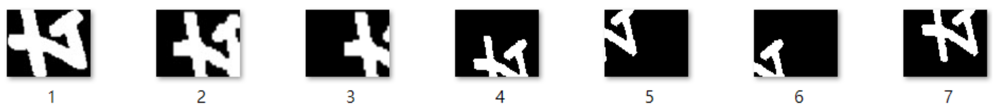
For each symbol, we prepared seven patterns to help the SVM classify correctly, as shown in
Figure 7 and
Figure 8. We tried to choose patterns from different angles and in different lights so that the system can adapt to more situations. We first chose different colors of the picture as our pattern but the correct rate was not satisfactory. The correct rate is determined by using seven target pictures as training patterns and another three pictures as testing patterns. We only checked the clearest and most complete squares to determine the correct rate, such as square 1 in
Figure 7 and
Figure 8. As long as we add more patterns, the correct rate of SVM-HOG will increase generally. However, each pattern for one symbol should not be too similar. When they are too similar, this means the overlap area for different patterns for the same symbol is above 80%. This would cause overfitting, which means the correct rate will be very low when there is a new target picture.
Figure 9 shows the database which includes 37 different symbols and 5 other shapes of the buttons on the screen.
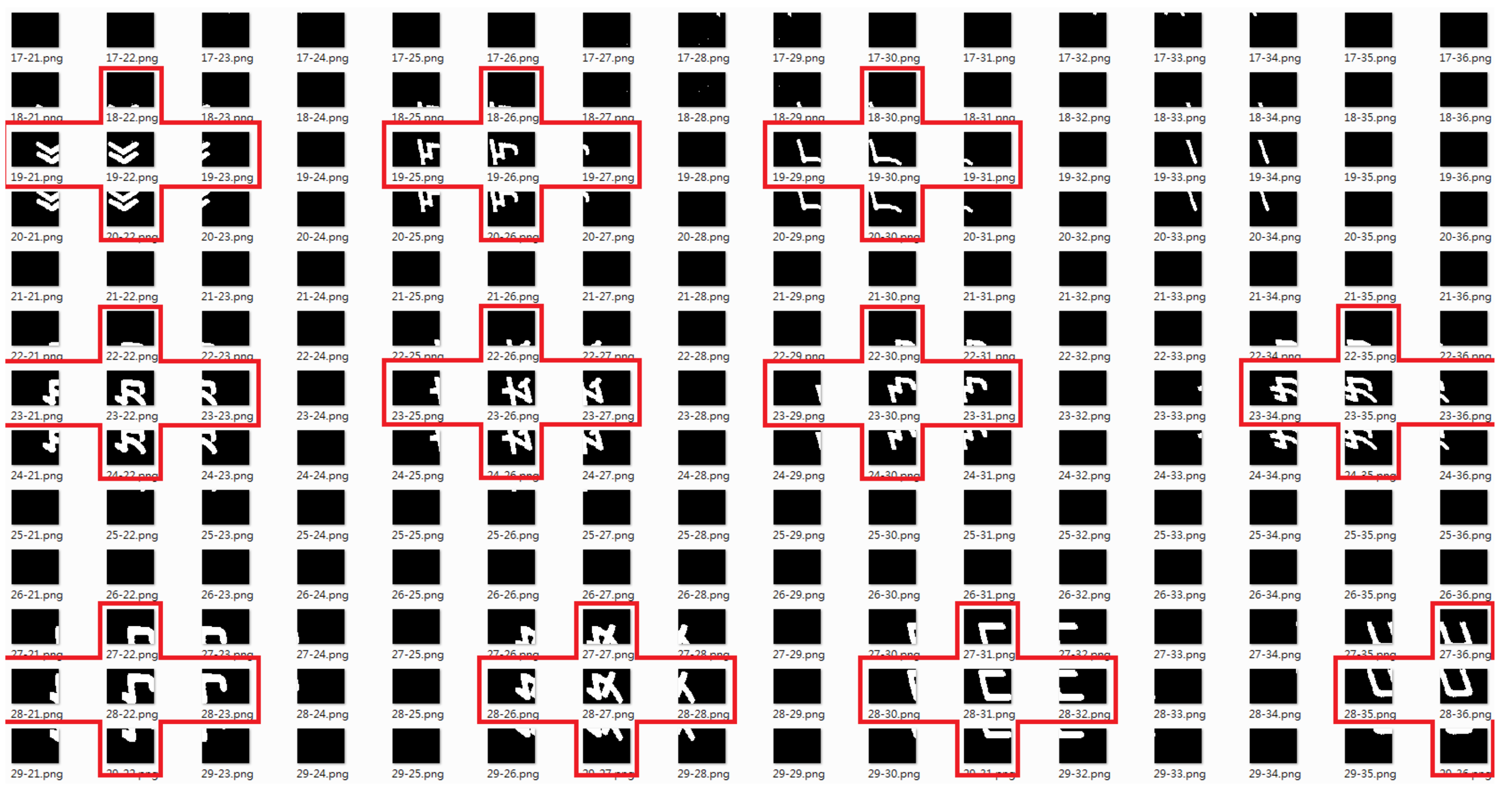
Each square includes one piece of coordinate information. When the SVM finishes classification, there will be several pieces of coordinate information for each classification, as shown in
Table 2 and
Table 3. We can see that the number of information in each classification is different because the correct rate of SVM-HOG is not 100 percent. If we calculate and compare the distance of each set of information, it will be difficult and costly. Therefore, we propose an idea which calculates the most common value. In
Table 2, the most common values are 820 and 1480, and in
Table 3, the most common values are 700 and 1440. This method is positive because there are about five correct squares in each classification, as the red line shown in
Figure 10 indicates. These five squares include the most common values of the
x-coordinate and
y-coordinate which lead to the correct square of the symbol. Instead of calculating all information, we only calculate one set of information which has the most common value. Using this method, the information of other squares will be abandoned immediately.
The recognition technique mainly includes two parts in this study, which are SVM-HOG and geometric matching. The Personal Computer (PC) screen only shows the commands of different characters (numbers or words) from the control system, and we can see that there is a strong contrast between the characters and the background. Smartphones also show the characters but we need to consider if the characters are in poor contrast with the background. Examples are shown in
Figure 11.
We use geometric matching [
21] to locate known references in the image. The image will not be affected by location, orientation, lightness and temperature changes. A desired sample model of the object can be created; then, the similarity of each image can be calculated based on this sample. This model is called a template and should be an ideal representation of the pattern or object. Whether the object is present or not is based on the similarity measurement. The similarity measurement is based on the Euclidean distance. The cross-correlation function is computed from the similarity measurement. If we want to use it for recognizing symbols on the virtual keyboard, we have to regulate the target picture and use YUV (luma component, blue projection and red projection) color space.
Figure 12 shows the metric based on the standard Euclidean distance between two sectors [
1].
I(
x,
y) is the common measure employed when comparing the similarity of two images (e.g., the template
p(
x,
y) and the test image
f(
x,
y)). The normalized cross-correlation (NCC) is used for finding incidences of a pattern or object within an image. NCC uses product concept and is scaled from 0 to 1. When
R equals 1, that means
p(
x,
y) equals
f(
x,
y).
The geometric component feature [
26] is a combination of several primitive features that consist of at least two primitive features, such as blobs, corners and edges. At location
x, the geometric feature vector can be calculated based on the reference point:
Here, x means the location of features, is the orientation and is the intrinsic scale. We determine the correct rate by using 10 target pictures from a camera with different lightness and different angles. The correct rate is 75 percent and geometric matching can successfully find coordinate information on the computer screen.
In addition, the proposed robot system needs to know whether it has pressed the correct button or not. Character recognition and image processes for a poor-contrast smartphone screen were added, which can confirm whether the pressed button is the desired button. The results of geometric matching are shown in
Figure 13. We make a decision by checking the command and geometric matching result. If the camera has been moved, this method can also recognize patterns and confirm the pressed button. When the image rotates, geometric matching can still find patterns and its coordinate information. We also set the system to search for patterns which are composed of a white background and black lines so that symbols on the virtual keyboard will not be considered.
4. Control Scheme
In most image processing applications, the camera that is used to capture the image has to be stationary. If the camera is moved, related coordinates must be calculated again. The test process will be disturbed in the factory and is very inefficient. In previous work, we used an improved back propagation (BP) neural network with the Levenberg–Marquardt Hidden-Layer Partition (LM-HLP) method [
38]. The LM-HLP method is excellent for training the relation of characters and coordinates. Block cyclic data distribution combined the characteristic of block distribution and cyclic distribution. Block distribution distributes source element arrays by the block size that we set up. Cyclic distribution distributes source element arrays to each processor applied by the serial number of the processor. The distribution example is shown in
Figure 14. The scheme, in this case, of LM-HLP is shown in
Figure 15. Here,
ai is the data to be identified and
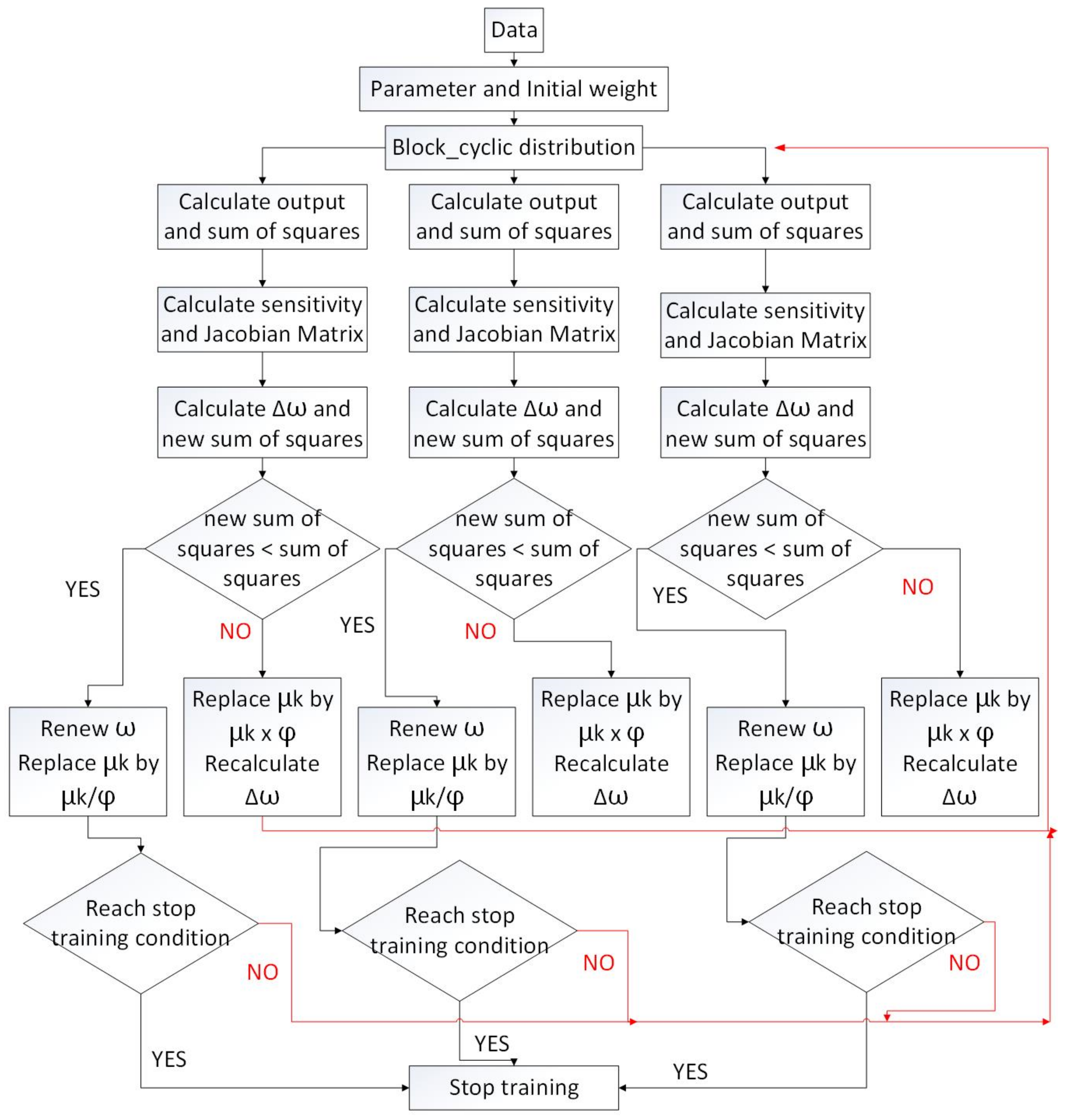
pi is the group number. The LM-HLP neural network uses block cyclic distribution on the parallel processing of the hidden layer. Input data are distributed in a block cyclic fashion to each processor for calculation. Each processor is a group, and the elements of each group are the same. This allows processors to calculate at same time, which reduces the learning time of LM-HLP. The flowchart is shown in
Figure 16. Once training is completed, the system can handle most situations of error recognition.
However, the camera must be stationary. Our solution is to make SVM-HOG keep calculating. As mentioned in previous section, and shown in
Figure 17 and
Figure 18, SVM-HOG does not require that the image be transformed from RGB color space to YUV color space, which is required with LM-HLP. The results of these two methods are almost the same. Further, SVM-HOG can recognize at least one square correctly and at most can recognize five squares correctly. This ensures that unexpected accidents will not disturb the process. We let the system execute SVM-HOG every 30 s, which keeps the robot arm from continuously pressing the wrong button. In addition to the camera being moved, the smartphone itself being moved has also been considered. As long as the smartphone is still in field of view of the camera, the proposed method is very useful.
Figure 19 and
Figure 20 show the camera being moved, which causes the target picture to change.
Figure 21 and
Figure 22 compare the changes between the original and latest coordinate information. Compare with [
38]: its scheme is executed every 30 s and can also complete this task, but the proposed method only uses 25 s and is custom fit to a Chinese and Mandarin phonetic symbols environment.
Fuzzy logic controllers have been utilized to control nonlinear systems successfully.
Figure 23 shows the position control scheme with the D-H model and a fuzzy controller. The target coordinates obtained from the camera are normalized and sent into the D-H model to obtain five angles for each joint of the robot arm.
Figure 24 shows the control sequence.
Fuzzy theory is used to reduce error between commanded and returned degrees of five servo motors. In a fuzzy system, the complex mathematical model of the robot arm is not required. Each layer has only one input and one output. Fuzzy rules are given as follows:
Rule 1: If Error is negative big, then M is NB.
Rule 2: If Error is negative small, then M is NS.
Rule 3: If Error is zero, then M is Z.
Rule 4: If Error is positive small, then M is PS.
Rule 5: If Error is positive big, then M is PB.
where Error is , M is θ, C is command degree and R is returned degree.
Fuzzy sets are NB, NS, Z, PS and PB, which represent turning negative big, negative small, zero, positive small and positive big, respectively.
Figure 25 shows the membership functions of the degree
Error.
Figure 26 shows the membership functions of the angle error.
Figure 27 shows the fuzzy control block diagram.
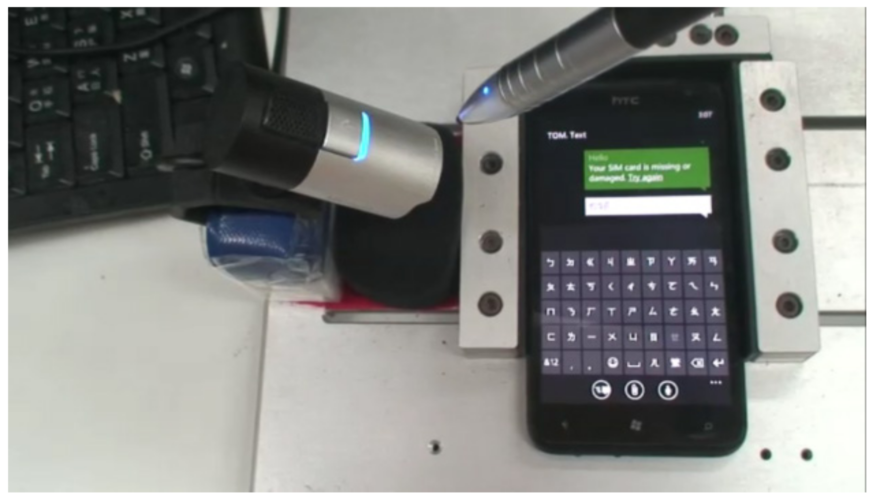
5. Experiments
In our experiments, we designed three kinds of motions for the robot arm; these are Automatically update coordinate information, Delete wrong symbols and Select the right Chinese characters.
Table 4 shows the recognition performance of different symbols and characters recognized by the proposed system. The average recognition rate is 90.3%. Symbols that are difficult to recognize are “ㄧ” and “ㄏ”, which is because of false recognition and unrecognized symbols. Performance can be improved by adding a dictionary process. The recognition accuracy can reach up to 98%. This experiment presents automatically updated coordinate information, as shown in
Figure 28. First, type four symbols “ㄋ”, “ㄧ”, “ㄏ”, “ㄠ” and characters “你好”. We used geometric matching to confirm whether it is right or wrong at every interval. Second, the camera is move to change the target picture. After the system calculates and updates the new coordinate information, we let the robot arm type four symbols, “ㄋ”, “ㄧ”, “ㄏ” and “ㄠ”, and the characters “你好” again with the new coordinate information. There are 15 steps in
Figure 28.
The next experiment presents the robot arm deleting wrong symbols, as shown in
Figure 29. We used geometric matching to confirm whether it is right or wrong at every interval. If the system fails to find a pattern, the robot arm will press the delete button and then press the right button again. For example, when the symbol “ㄨ” appears on the screen but not the symbol “ㄏ”, then the system will fail to find the pattern “ㄏ”. There are eight steps in
Figure 29.
The last experiment presents a mechanism for the robot arm to select the right Chinese characters, as shown in
Figure 30. The purpose of this mechanism is to make system select the correct characters without the five tones in Traditional Chinese. With geometric matching, the system does not need to press all of steps as in the first experiment. There are five steps in
Figure 30.
An intelligent control scheme based on image processing, SVM-HOG, the D-H model and fuzzy control was applied to a robot arm for position control. Using these methods, the control system can compute an accurate position of the coordinate information that results in a success rate of symbol recognition of up to 98% in real time. Characters can be checked by the use of geometric matching.
Table 5 shows the success rates of experiments after 10 times. The second mechanism, Delete wrong symbols, has the lowest success rate. Because different wrong symbols will cause different results, there are some symbols very similar to each other and they are difficult to identify. The third mechanism, Select the right Chinese characters, has the highest success rate because the pattern of Chinese characters is very clear to recognize.
6. Conclusions
This study proposed a control scheme that applied pattern recognition, fuzzy control, and SVM-HOG to a robotic smartphone testing system that can replace manual testing and reduce manpower. The inverse kinematics, SVM-HOG, fuzzy theory, and transformation between webcam coordinates and robot arm coordinates are used for catching the digits or letters outside of the target center. The solution for the inverse kinematics is obtained by use of the D-H model. The images are transformed from the RGB color space to the binary color space. Generally speaking, binary color space is not necessary for SVM-HOG. SVM-HOG is also capable of analyzing and classifying RGB color space images, but for a higher correct rate and geometric matching, transforming RGB color space to binary color space is less burdensome than transforming to YUV color space. A frame of image is cut into small squares, and its half part is the same as the previous one. The SVM classifies symbols with 42 classifications after the HOG analyzes features of the squares. Vision Assistant allows one to configure and benchmark a sequence of visual inspection steps and apply a visual inspection system for automated inspection. A geometric matching recognition program has been employed by the use of NIVA, and patterns can be corrected by a dictionary process. In addition, characters can be checked by image-processing techniques and the program is able to recognize patterns that are incomplete. In the control scheme, the robot system can compute a position in real time using the D-H model and fuzzy controller. By converting coordinates every time through the D-H model, the degrees of robot joints can be updated by SVM-HOG. Recognition accuracy is 90.3% for images taken from the webcam and 98% after using a dictionary process. From the experiments, the proposed control scheme can allow the robot arm to perform different mechanisms of the smartphone test in a Traditional Chinese language environment successfully. Most importantly, the robot arm is able to deal with the situation of the camera or smartphone being slightly moved. The limitation is that the movement of the camera or the smartphone cannot be greater than 1 cm, and in such a case, the system setup needs to be recalibrated.


