Article

Novel Thermal Management Strategy for Improved Inverter Reliability in Electric Vehicles

1
Industry and Transport Unit, Tecnalia Research and Innovation, 48160 Derio, Spain
2
Department of Electronic Technology, University of the Basque Country (UPV/EHU), 48013 Bilbao, Spain
3
Departament d’Enginyeria Electrònica, Institut d’Organització i Control, Universitat Politécnica de Catalunya (UPC), 08028 Barcelona, Spain
4
Infineon Technologies AG, Am Campeon 1-15, 85579 Neubiberg, Germany
*
Author to whom correspondence should be addressed.
Appl. Sci. 2020, 10(22), 8024; https://doi.org/10.3390/app10228024
Submission received: 20 October 2020 / Revised: 8 November 2020 / Accepted: 10 November 2020 / Published: 12 November 2020
(This article belongs to the Special Issue Modeling, Design and Control of Electric Machines)

Abstract

:

Featured Application

Battery powered electric vehicles.

Abstract

Requirements for electric vehicle (EV) propulsion systems—i.e., power density, switching frequency and cost—are becoming more stringent, while high reliability also needs to be ensured to maximize a vehicle’s life-cycle. Thus, the incorporation of a thermal management strategy is convenient, as most power inverter failure mechanisms are related to excessive semiconductor junction temperatures. This paper proposes a novel thermal management strategy which smartly varies the switching frequency to keep the semiconductors’ junction temperatures low enough and consequently extend the EV life-cycle. Thanks to the proposal, the drivetrain can operate safely at maximum attainable performance limits. The proposal is validated through simulation in an advanced digital platform, considering a 75-kW in-wheel Interior Permanent Magnet Synchronous Machine (IPMSM) drive fed by an automotive Silicon Carbide (SiC) power converter.

1. Introduction

Transport is one of the main sources of greenhouse gas emissions of anthropogenic origin. For example, road transport accounts for 27% of total emissions in Europe, being the greatest contributor among all sectors [1]. There is almost a consensus on the idea that a shift to electro-mobility will be mandatory to meet the Paris Agreement goals, as is confirmed by the meta-analysis conducted in [2]. In this context, a comprehensive evaluation of CO 2 emissions generated by battery powered electric vehicles (EV) vs. internal combustion engine (gasoline and diesel) vehicles has been conducted in [3]. A life-cycle assessment (LCA) was carried out considering not only emissions during vehicle operation, but also the ones generated from fuel extraction, refining, power generation, raw material extraction, vehicle manufacturing, regional particularities (electrical mix, driving distances, etc.), maintenance and end-of-life phase. The authors in [3] conclude that, with some particular exception, the longer the EV’s driven distance, the more the CO 2 emissions would be reduced (note that battery manufacturing significantly penalizes EVs in terms of emissions), performing research focused on improving reliability and maximizing the life-cycle of EVs extremely important. In particular, EVs in Europe would outperform gasoline and diesel vehicles regarding emissions from a range of 76,545 km and 109,415 km, respectively.
However, for the general adoption of battery powered EVs by end users, features need to be comparable to the ones of internal combustion engine based vehicles. Thus, ambitious technological targets have been set for both electric machines (power density of 5.7 kW/L, overall efficiency of 93% and cost of 4.7 $/kW) and power electronics (power density of 13.4 kW/L, overall efficiency of 97% and cost of 3.3 $/kW) [4]. With regard to high power density and efficiency requirements, surface mounted or interior permanent magnet synchronous machines (PMSM) are commonly adopted [5,6,7,8]. Current trends on PMSM technology focus on multiphase configurations [9,10], high speed electric machines (HSEM) [11,12,13], and on in-wheel direct drive solutions [14,15]. In this context, wide band-gap semiconductor technologies are being investigated for their introduction in PMSM drive power inverters [16,17] due to the following reasons:
(i)
Both HSEM and in-wheel multi-pole direct drive solutions lead to high electrical stator frequencies. These trends exhibit regulation issues to be addressed [13,18,19], which can be overcome by introducing power electronics technologies that can operate at high switching frequencies with reasonable power losses [20].
(ii)
Cost reduction trends consider sharing the high temperature cooling loop of the electric machine (at 105 C) with power electronics [21,22], or also using air cooling technologies that adopt convenient power converter placement to take advantage of circulating air during EV motion [23]. Thus, the utilization of power semiconductor technologies that can withstand higher junction temperatures is required [20].
As a consequence of such stringent operation conditions, reliability of power converters can be jeopardized. According to [24], approximately 60% of power semiconductor breakages are a consequence of thermal issues. Moreover, an increment of 10 C in the operation mean temperature of a power semiconductor can double its failure-ratio [25]; consequently, special care of inverter thermal management must be taken. Such failures are a consecuence of the mismatches between the coefficients of thermal expansion of the materials that constitute power modules, which suffer from significant thermo-mechanical fatigue during thermal or power cycling [26].
In such a context, operation point-dependant predefined current and/or switching frequency derating schemes are commonly used in the traction industry to avoid excessively high junction temperatures. However, in many cases such derating values can be conservative, and the operation limits of the drive can be reduced unnecessarily [27]. Thus, the incorporation of active thermal management solutions is being investigated to maximize vehicle performance. Active control of power losses can be applied in different layers (drivers, modulation and control) of an electric drive [28]. Control approaches aiming at the active modification of the PWM strategy (changing between different space vector sequences, continuous and discontinuous) are presented in [29]. Simple switching frequency hysteresis regulators can also be implemented [29]. Although hysteresis regulators are mainly used by the industry due to their simplicity, their unique usage possesses some drawbacks, as they do not cancel steady state errors. Thus, more advanced approaches can be found in the literature. For example, the authors in [27,30] propose a control algorithm for traction drives that considers electro-thermal constraints and real-time temperature estimation to impose current (torque) and switching frequency limits. By incorporating not only hysteresis but also discrete regulators, such limits are modified to precisely track a given temperature constraint. Similarly, an active thermal management algorithm is proposed in [31] based on a model predictive controller.
In this work, a novel online Temperature Constraint Tracking (TCT) based switching frequency regulator is proposed to improve the reliability of automotive power converters in the whole EV operation range: (i) at low speeds and standstill, where high acceleration and regenerative braking is required under urban traffic; (ii) at high speeds, where controllability needs to be ensured by determining a minimum switching frequency value. This novel solution focuses on simplicity and low computational burden, as automotive microcontrollers have limited processing capabilities and the incorporation of an increasing number of software functionalities is demanded by the industry. The proposal is successfully incorporated in the control architecture of a 75 kW in-wheel direct drive IPMSM fed by an automotive grade Silicon Carbide (SiC) power converter, and is validated in an OPAL-RT RT-Lab OP4510 platform by means of simulation under realistic driving conditions.

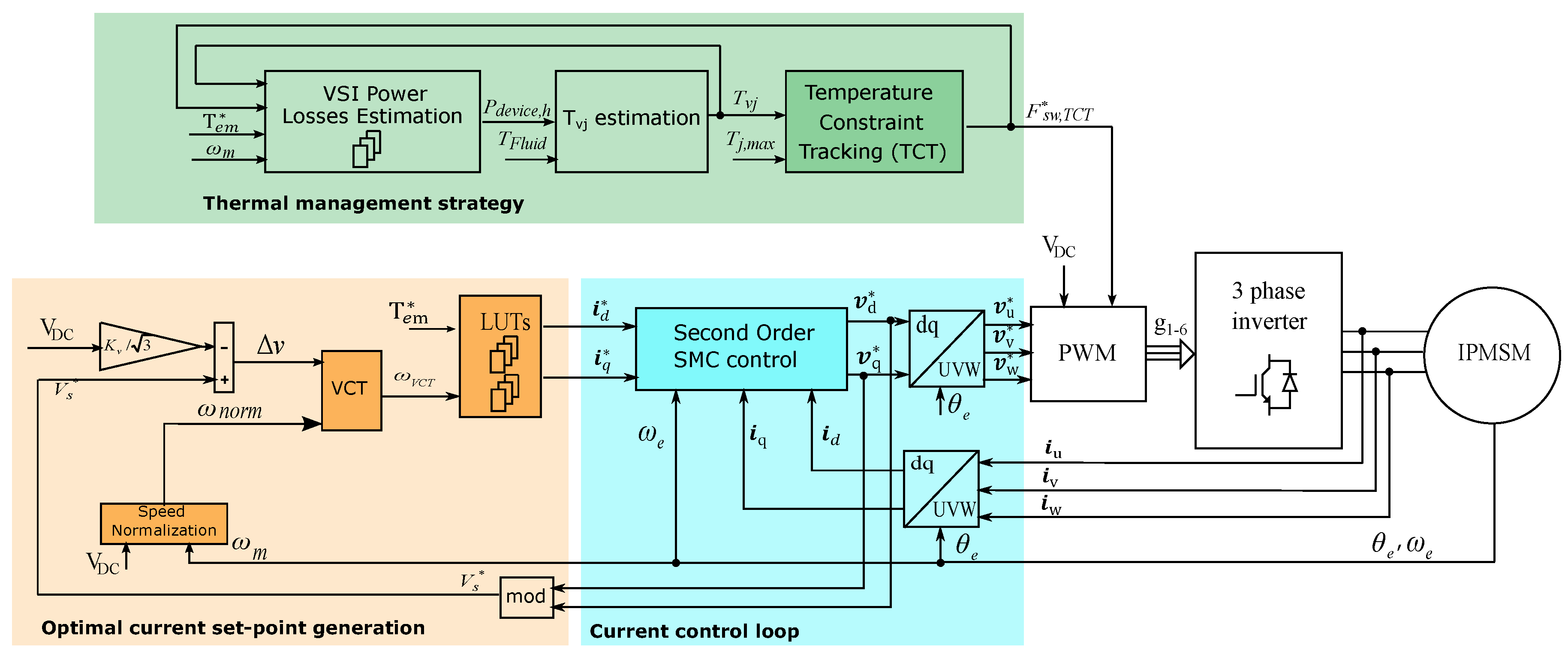
2. Torque Regulation of the IPMSM

Figure 1 shows the general diagram of the implemented IPMSM torque regulation strategy including an optimum set-point generation block, a field oriented current control loop (with the required vector transformations), and the proposed TCT thermal management strategy, this last one incorporating a power loss estimator, a highest virtual junction temperature estimator and a TCT algorithm.
From the reference torque T e m , the current set-point generation block determines the i d and i q stator current references from two 2-D Look-Up Tables (LUTs). (From data obtained by Finite Element Analysis (FEM), current trajectories are determined offline and stored in the LUTs for Maximum Torque Per Ampere (MTPA), Field Weakening (FW) and Maximum Torque Per Volt (MTPV) regions. DC-link voltage dependency has been eliminated from the LUTs using the speed normalization ( w n o r m ) concept proposed in [32], requiring one less dimension in the LUTs.) Unlike in conventional LUT-based current set-point generation approaches [33], the controller incorporates an additional Voltage Constraint Tracking feedback loop (VCT, Figure 1), ensuring that maximum stator voltage modulus of V D C / 3 is never exceeded during field weakening even if significant electrical machine parameter deviations exist [34].
Once the reference currents are determined, the IPMSM torque is indirectly regulated by the current control loop. This loop follows the well-known field oriented control (FOC) approach in the synchronous reference frame ( d q ). However, although PI-based regulators are generally used, a second order Sliding Mode Control (SMC) with super-twisting has been implemented, as such an approach is more robust under machine non-linearities that are common in automotive IPMSMs [34,35].
The d q reference voltages to be synthesized by PWM have been obtained by [34]:
v d = v d , S T + v d , e q ,
v q = v q , S T + v q , e q ,
where v d , e q (3) and v q , e q (4) are the equivalent control signals, while v d , S T and v q , S T are computed by applying the Super-Twisting Algorithm (STA) in (5) and (6).
v d , e q = L d c d e i d R s i d + w e Ψ q ( i d , i q ) L d ( i d , i q ) ,
v q , e q = L q c q e i q R s i q w e Ψ d ( i d , i q ) L q ( i d , i q ) ,
v d , S T = L d λ d | s i d | 1 / 2 s g n ( s i d ) + Ω d s g n ( s i d ) d t ,
v q , S T = L q λ q | s i q | 1 / 2 s g n ( s i q ) + Ω q s g n ( s i q ) d t ,
where R s is the stator resistance, L d ( i d , i q ) , L q ( i d , i q ) , Ψ d ( i d , i q ) and Ψ q ( i d , i q ) are the current dependant stator inductances and fluxes, ω e is the electrical speed, e i d = ( i d i d ) and e i q = ( i q i q ) are the error signals, c d , c q , λ d , λ q , Ω d and Ω q are the positive gains for tuning, s g n ( s i d ) = s i d / | s i d | , s g n ( s i q ) = s i q / | s i q | , where s i d and s i q are the sliding surfaces:
s i d = e i d + c d e i d d t ,
s i q = e i q + c d e i q d t .

3. Proposed Thermal Management Strategy

The thermal management strategy (Figure 1) is responsible for regulating the switching frequency F s w , T C T of the PWM to keep semiconductors’ junction temperatures below excessive limits. As a first step, the highest virtual junction temperature T v j between all of the power semiconductors must be determined by this block prior to sending it to the TCT algorithm. This procedure is detailed in the next section.

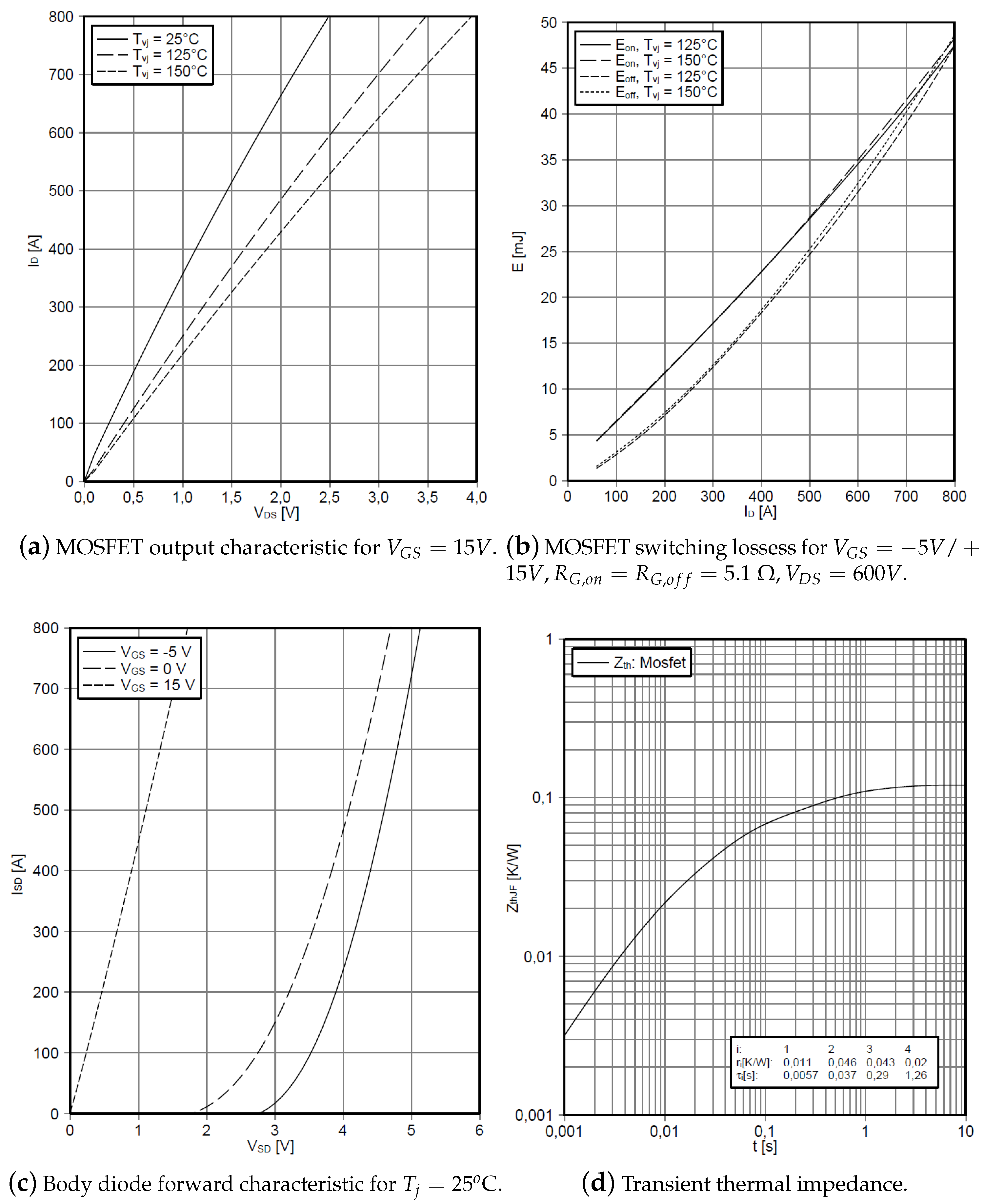
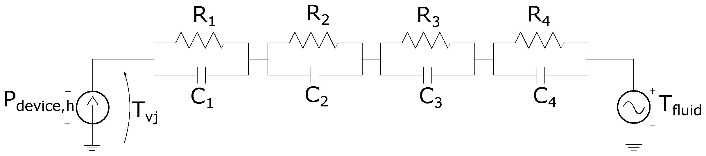
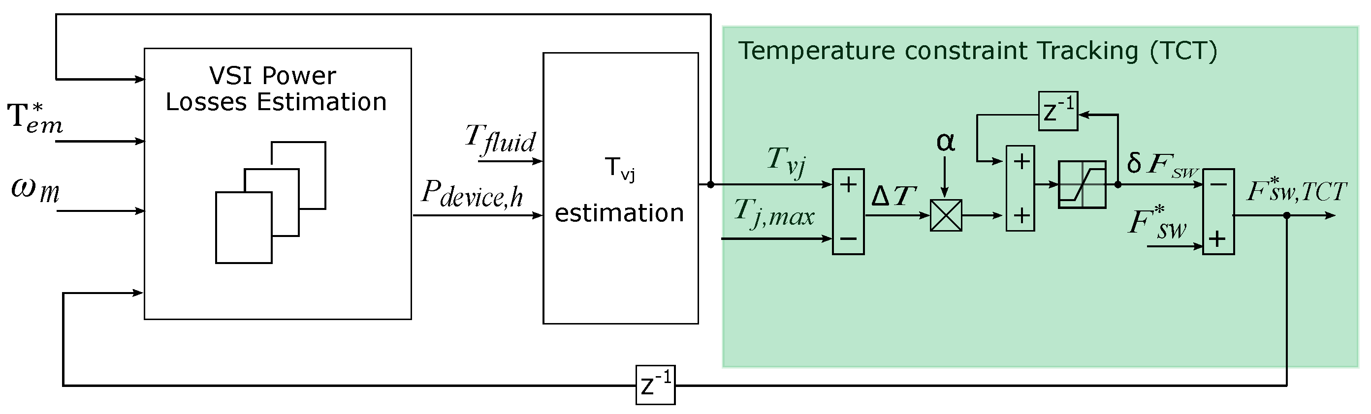
3.1. Power Loss and Highest Virtual Junction Temperature Estimation

In general, two possible approaches can be considered to estimate the highest T v j among all switches:
  • If reliable estimation of semiconductor T v j through temperature measurement sensors (thermistor, NTC or PTC) soldered on the Direct Bonded Copper (DBC) substrate of the power module is possible [36], the highest of all the estimated temperatures is provided to the TCT algorithm for its regulation. (As temperature sensors are placed at a given distance to the semiconductor die, it provides a lower temperature than T v j . To obtain accurate results, such a measurement point can be treated as a node within a simplified Foster thermal network to compensate the temperature underestimation (which is not straightforward) or, for simplicity, a security margin can be considered instead [36].)
  • If the previous is not possible, temperature should be estimated by using accurate thermal and power loss models in conjunction with an external temperature sensor (measuring heatsink or coolant temperature) [36]. This approach has been proven successful in [27,30], as estimated and measured temperatures matched very well. In such works, power losses of all semiconductors were estimated online.
This work follows the latter approach for the temperature estimation. However, as stated in the introduction of the document, low computational burden is a key feature demanded by the automotive industry. Thus, it is proposed to calculate the highest single semiconductor average power losses (worst case) per electrical period offline for all the torque/speed map of the machine and store these results in a 4-D LUT (Figure 1), considering T v j , F s w , T e m and ω m as inputs. (Although at high speeds the junction temperatures are balanced, unbalances occur at very low speeds that need to be considered for obtaining accurate estimations.)
For the offline power loss estimation, an accurate electric drive model has been implemented in Matlab/Simulink incorporating a per-device power loss model. In this work, a novel automotive grade SiC power module FS03MR12A6MA1B [37] of Infineon Technologies has been used to validate the proposal. This module offers state-of-the-art Trench SiC MOSFET technology with very low switching and conduction losses, which is necessary to reach high efficiency in traction inverters. It is packaged in a stray-inductance optimized module, which is also necessary for reaching high switching speeds as the ones considered for this application ( f s w = 25 kHz). Figure 2 shows the most significant power loss related parameters considered from the datasheet.
Regarding MOSFETs, the average conduction ( P c o n d , M O S ) and switching ( P s w , M O S ) losses during a modulation period T s w are calculated as:
P c o n d , M O S = 1 T s w 0 T s w V D S ( i D , T v j , M O S ) i D ( t ) d t ,
P s w , M O S = 1 T s w V D C V D C ( t e s t ) K V [ E O N ( i D , T v j , M O S ) + E O F F ( i D , T v j , M O S ) ] ,
where V D S ( i D , T v j , M O S ) is the drain-to-source voltage drop (Figure 2a), i D ( t ) is the drain current, T v j , M O S is the virtual junction temperature of the MOSFET, E O N ( i D , T v j , M O S ) and E O F F ( i D , T v j , M O S ) are the energy losses produced during turn-on and turn-off (Figure 2b), V D C is the DC-link voltage value, and V D C ( t e s t ) is the blocking voltage from which E O N ( i D , T v j , M O S ) and E O F F ( i D , T v j , M O S ) were calculated by the manufacturer [38]. For the sake of simplicity, the compensation factor K V 1 .
Similarly, the average conduction losses of the body diode during a modulation period are calculated as [38]:
P c o n d , D = 1 T s w 0 T s w V S D ( i S D , T v j , D ) i S D ( t ) d t ,
where V S D ( i S D , T v j , D ) is the body diode forward voltage (Figure 2c), i S D ( t ) is the current circulating through the body diode, and T v j , D is the diode virtual junction temperature. Note that in SiC MOSFETs the reverse recovery energy loss E R R is negligible; thus, diode switching losses P s w , D have not been considered. Additionally, as both MOSFET and body diode share the same die, it has been considered that T v j , M O S T v j , D T v j .
When executing the thermal management strategy online (Figure 1), highest average power losses of a power device ( P d e v i c e , h = P c o n d , M O S + P s w , M O S + P c o n d , D ) are estimated at each modulation period from the precalculated 4-D LUT, according to the operation point of the power inverter. Then, fluid temperature T f l u i d is measured, and T v j is calculated from the equivalent Foster network (Figure 3) whose thermal resistances R i and capacitances C i have been obtained form the datasheet (Figure 2d). Note that the R t h nomenclature used follows the AQG 324 Automotive Qualification Guideline. A detailed explanation regarding R i and C i estimations can be found in [39].
The transient thermal impedance Z t h , J F of the circuit of Figure 3 can be expressed in the Laplace domain as follows:
Z t h , J F = i = 1 n R i 1 + τ i s ,
where n is the number of the RC equivalent circuits and τ i = R i C i . For the digital implementation of the foster network, such continuous transfer function is transformed into the z domain, with a sample-time of T s w , and T v j is numerically obtained.

3.2. Temperature Constraint Tracking Algorithm

Finally, the estimated highest T v j value is sent to the TCT algorithm, whose block diagram is shown in Figure 4. This regulator aims not to exceed a given temperature limit T j , m a x by computing the difference between T v j and T j , m a x :
Δ T = T v j T j , m a x .
The switching frequency of the PWM modulator, determined by the TCT algorithm for the k-th instant is:
F s w , T C T ( k ) = F s w δ F s w ( k ) ,
where F s w is the predefined PWM frequency of the inverter and δ F s w is a correction term that reduces the switching frequency when T v j exceeds T j , m a x :
δ F s w ( k ) = δ F s w ( k 1 ) + α Δ T ,
where α is a positive tunable parameter that sets the dynamics of the TCT algorithm.
Finally, the correction term δ F s w is saturated as follows:
δ F s w ( k ) | s a t = 0 i f δ F s w ( k ) 0 , F s w F s w , m i n ( k ) i f δ F s w ( k ) > 0 .
Saturation in (16) has two purposes. On the one hand, the predefined switching frequency F s w cannot be exceeded; thus, δ F s w is saturated to zero when the compensation term is positive. On the other, the minimum switching frequency that ensures electric machine controllability ( F s w , m i n ( k ) ) for the operation conditions of the k-th instant is established as follows:
F s w , m i n ( k ) = f e ( k ) S p = ω m ( k ) P 2 π S p ,
where f e ( k ) is the electrical frequency of the IPMSM in the k-th instant, P is the pole-pair number of the machine, ω m ( k ) is the mechanical speed of the machine, and S p is the number of samples per period required to ensure system controllability. In this work, S p has been set to eight, while the minimum value that F s w , m i n can acquire has been saturated to 2 kHz in order not to exceed a given torque ripple during near standstill operation. (Despite some recent research works [13,40,41] try to minimize the S p to as low as 2 in order to fulfil the well-known Nyquist frequency (which must be half of the sampling one in order to guarantee stability); it is known that the conservative value should not be lower than 8.)

4. Validation of the Proposed Thermal Management Algorithm

4.1. Simulation Platform Description

The proposed thermal management algorithm has been validated in an advanced simulation platform. An RT-Lab OP4510 real-time simulator (OPAL-RT, Montreal, QC, Canada) with four computational nodes (Intel Xeon E3 v5 CPU, 8MB cache, 3.5GHz, 16G B RAM, 128 GB SSD) has been used to accelerate simulations and evaluate the performance of the proposal under realistic driving conditions. On the one hand, a rear-wheel drive SUV Full Electric vehicular model has been implemented, whose mathematical model is summarized in Appendix A. The vehicle powertrain has two in-wheel electric machines fed by two three-phase power inverters constituted by the SiC semiconductors presented in Section 3.1, whose most significant parameters are shown in Table 1. In this application, a nominal switching frequency of 25 kHz has been selected to take advantage of the SiC technology capabilities. This way a smooth operation is provided when operating at very high electrical frequencies that result due to the multi-pole nature of the machine. Note also that, for cost saving, both the electric machine and the power inverter share the same high temperature liquid cooling loop. Table 2 shows the nominal parameters of each 75 kW IPMSM, while the TCT control settings are provided in Table 3. Note that, in the following section, a single in-wheel drive is simulated.
In the following section, thermal management validation tests under low speed operation (close to standstill operation) and during a World Harmonized Light-duty Vehicle Test Procedure (WLTP) [42] driving cycle are provided.

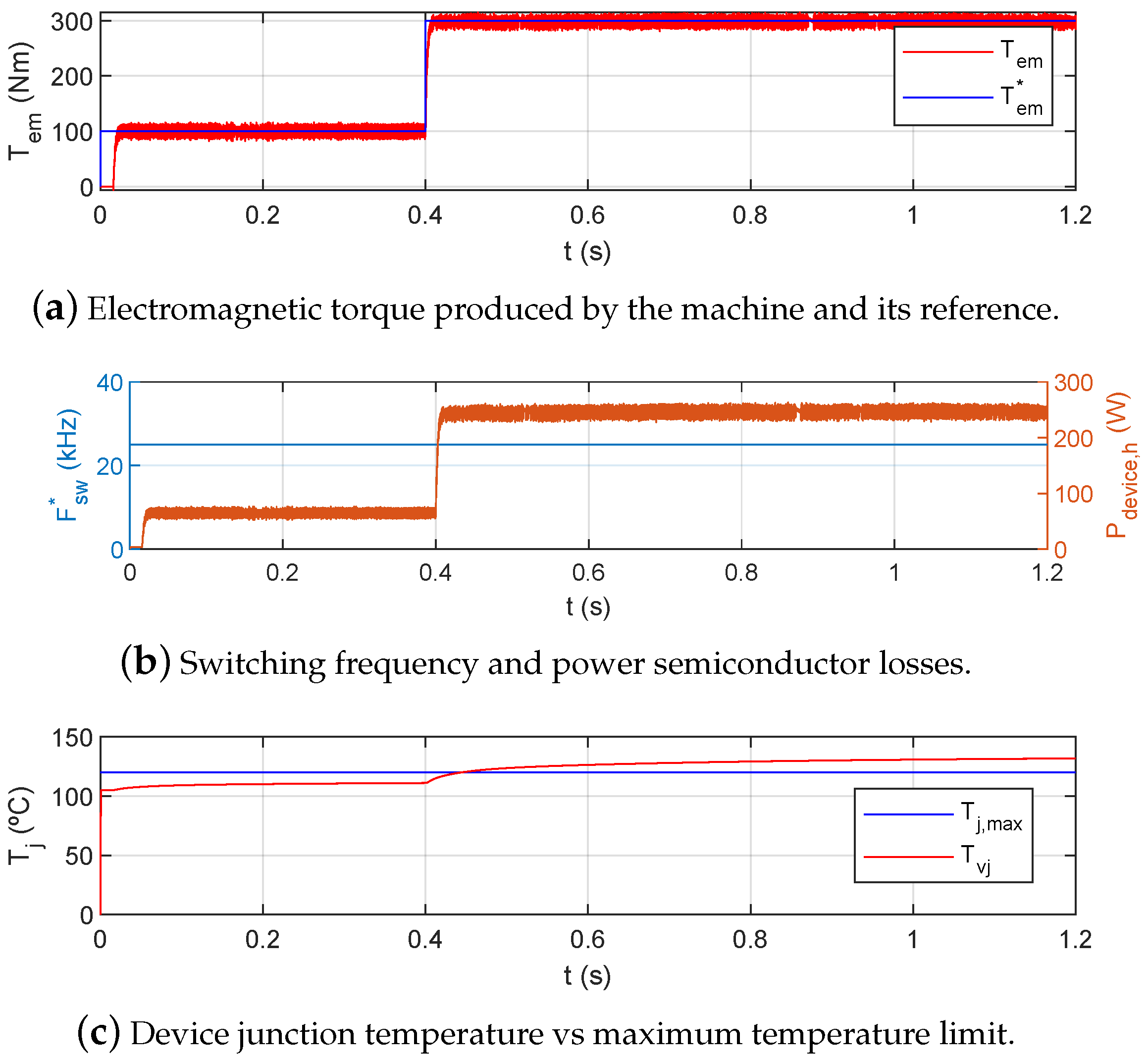
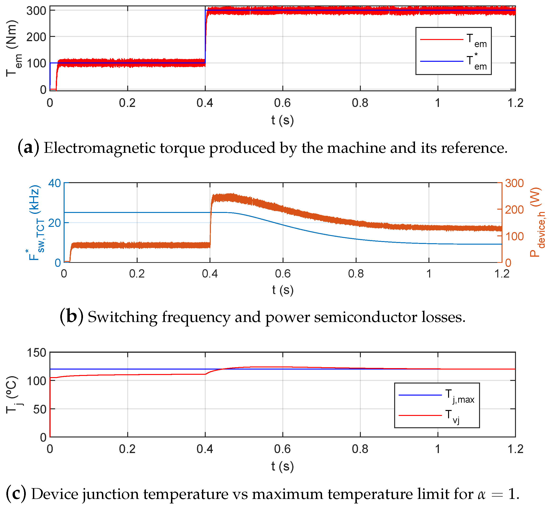
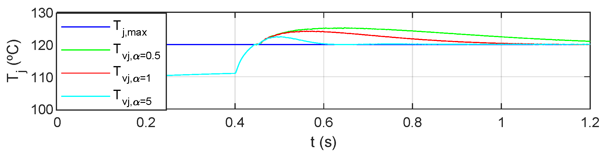
4.2. Low Speed and High Torque Operation Results

EV drives usually operate at low speeds with high torque, for example starting uphill, or also when driving in urban driving conditions with a dense traffic, intersections and traffic lights. These operation conditions are critical, as at very low speeds power losses are concentrated in a few power semiconductors, which implies high junction temperatures. Thus, a high torque step demand (from 100 Nm to 300 Nm) has been simulated while driving at ω m = 1 rpm (Figure 5a).
When no TCT algorithm is applied, the high power losses on the semiconductors produced by the high torque step (Figure 5b, from t = 0.4 s) result on a high junction temperature (Figure 5c). As a consequence, the power converter overheats, significantly reducing its life-cycle if such operation conditions are constantly repeated. However, such temperature can be constrained by using the proposed thermal management algorithm (Figure 6). Figure 6b shows that power losses are reduced when the TCT algorithm reduces the switching frequency from 25 kHz to approximately 10 kHz, maintaining the temperature around the maximum allowed one, which in this work has been set at 120 C (Figure 6c). Note that the switching frequency regulation dynamics can be set by adjusting such a parameter. In this context, Figure 7 exemplifies the temperature response of the system obtained for various values of α . The higher the value of α , the faster the settling time and the lower the overshoot. However, a trade-off between temperature settling time and current regulation robustness must be considered. In this particular application, the TCT regulation parameter α has been set to 1.
It is important to remark that a small temperature overshoot (Figure 6c) has been produced due to the high torque step. However, as torque reference is always ramped in EVs to ensure driving comfort and vehicle’s mechanical integrity, the TCT algorithm has enough time to react and ensure that the power semiconductor junction temperature does not exceed a given temperature constraint.

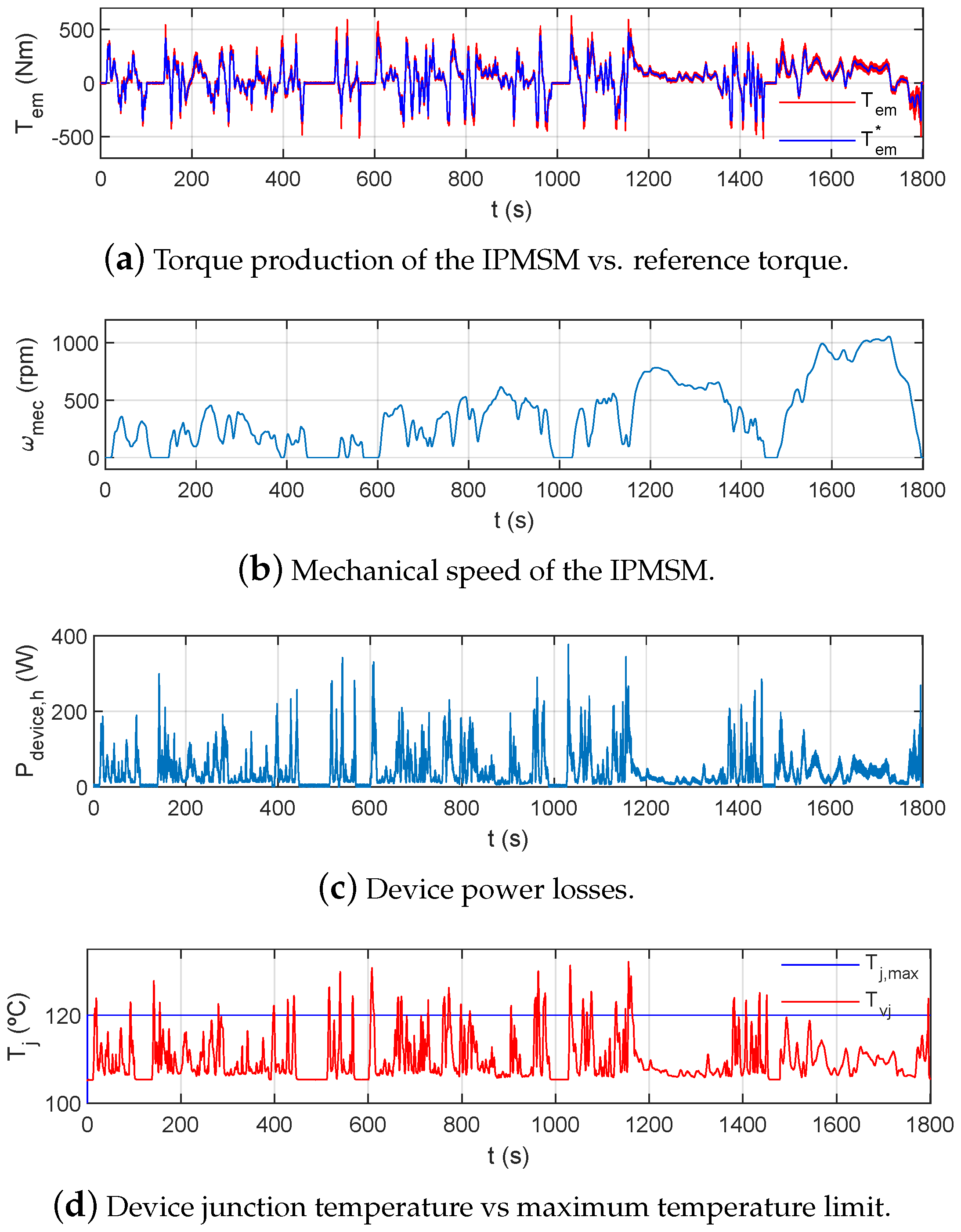
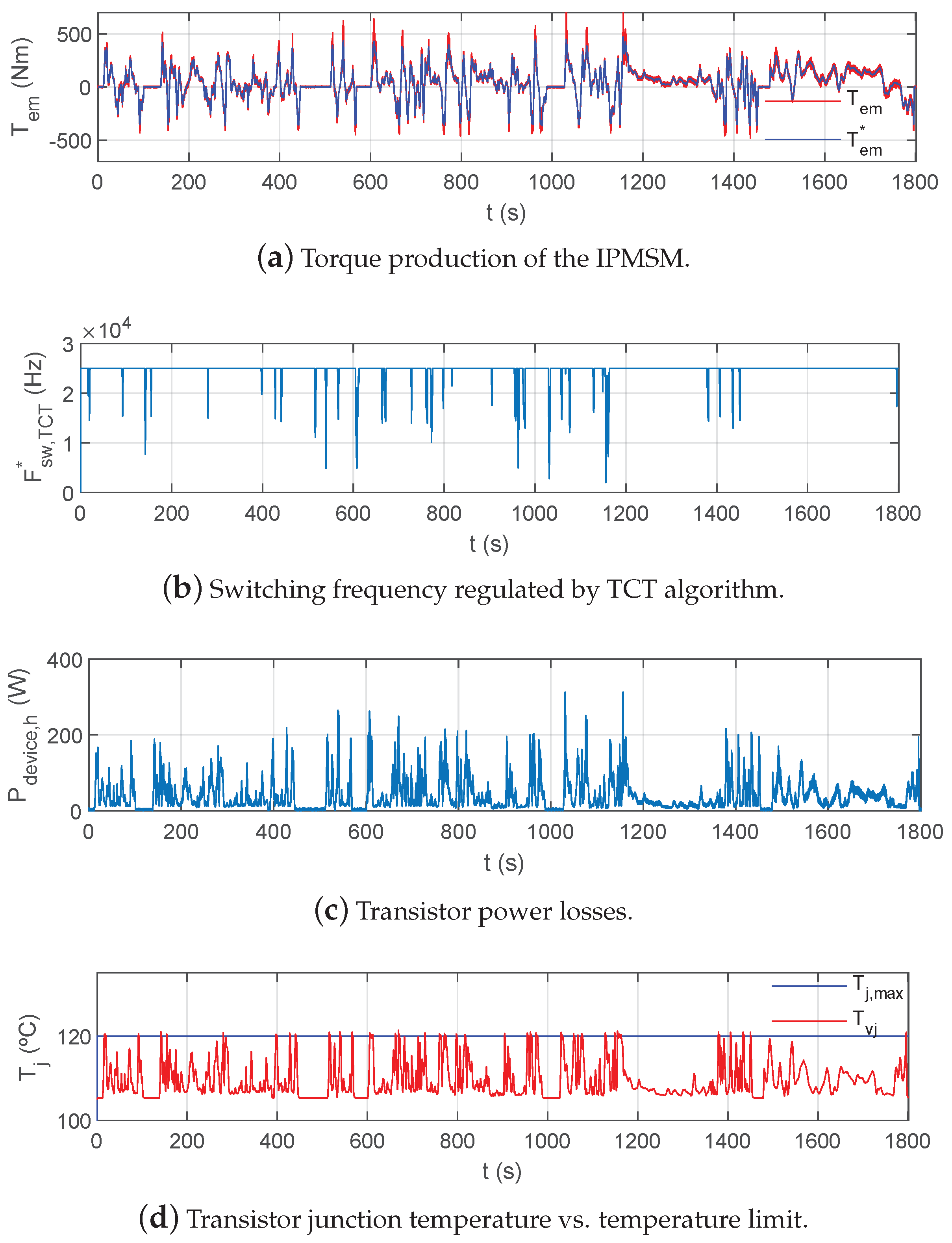
4.3. Validation under Standardized WLTP Driving Cycle

Finally, the proposed TCT algorithm has been evaluated through a WLTP driving cycle. Figure 8 shows the results obtained when the thermal management strategy is not active. In this scenario and as a consequence of the high power losses (Figure 8c), T j , m a x is exceeded in various intervals of the WLTP cycle (Figure 8d). However, when using the proposed thermal management approach (Figure 9), the junction temperature does not exceed the limit value thanks to the regulation of the switching frequency (Figure 9d). It is important to remark that when the junction temperature remains under the maximum limit, δ F s w is saturated to zero, and the nominal switching frequency is restored to its default value of 25 kHz. Additionally, as shown in Figure 9a, the thermal management strategy does not interfere in the normal operation of the drive, extending its life-cycle and helping to achieve the C O 2 emission reduction goals. Although a slightly higher torque ripple is present when the TCT algorithm reduces the switching frequency, its effects are filtered by the EV’s large inertia, making such a ripple negligible for the passengers’ comfort.

5. Conclusions

Maximizing the life-cycle of modern EVs and their constituting elements is a relevant research topic. Due to the increasingly demanding requirements of the automotive industry, EV traction inverters must operate under high power semiconductor junction temperatures and stringent thermal cycles. Under these extreme working conditions it is difficult to ensure the power converter reliability while not excessively reducing the performance of the drive. In this context, a novel online thermal management algorithm based on a TCT switching frequency regulator that maintains the semiconductors’ junction temperature below excessive temperatures has been proposed in this paper. The algorithm has been designed to be easily fitted in automotive microcontrollers in order to meet the always exigent computational requirements of the automotive industry.
A realistic 75 kW in–wheel direct drive IPMSM fed by an automotive grade SiC power converter has been accurately modelled and used to validate the proposal through numerous and precise simulations, which also include standardized and therefore representative driving cycles. From the results obtained, it can be concluded that the introduction of the proposed TCT algorithm improves the thermal behaviour of the drive power converter without jeopardizing the system controllability and performance. As a final remark, it is worth mentioning that for some applications where a much lower temperature constraint or more severe load conditions are imposed, only regulating the switching frequency could not be sufficient to track the temperature limit. In such cases, the proposed thermal management strategy could be extended by incorporating a torque limiting regulator.

Author Contributions

E.T.: conceptualization, thermal management algorithm implementation, analysis, original draft preparation; E.I.: RT-Lab simulation, original draft preparation; P.P.: Vehicular model implementation, review and editing; A.A.: Torque regulation algorithm, review and editing; A.L.: SiC power module characterization; A.P.P.: SiC power module characterization and document review. All authors have read and agreed to the published version of the manuscript.

Funding

This work has been supported in part by the European Commission through ECSEL Joint Undertaking (JU) under Grant Agreement No. 783174 (HiPERFORM project), by the Government of the Basque Country within the research program ELKARTEK as the projects ELPIVE (KK-2019/0006) and ENSOL 2 (KK-2020/00077), by the Government of the Basque Country within the fund for research groups of the Basque University system IT978-16, by the Government of Spain through the Agencia Estatal de Investigación Project DPI2017-85404-P, and by the Generalitat de Catalunya through the Project 2017 SGR 872.

Conflicts of Interest

The authors declare no conflict of interest.

Appendix A. Mathematical Model of the Vehicle

In this appendix, the mathematical expressions of the backward model used for vehicular simulation are presented. In an in-wheel direct drive, the mechanical speed ω m and torque of the drive T e m equal the ones of the wheel. For a given EV linear speed of v d c , the wheel angular speed and torque can be determined by:
ω m = ω w h e e l = v d c r w h e e l ,
T e m = T w h e e l = r w h e e l ( F R o l l + F A e r o + F I n e r t i a ) ,
where r w h e e l is the wheel radius, and F R o l l , F A e r o , and F I n e r t i a are the rolling resistance, aerodynamic resistance, and inertia forces, respectively. These last three can be defined as:
F R o l l = μ a g M c a r ,
F A e r o = ρ v d c 2 C d A f 2 ,
F I n e r t i a = M c a r ( 1 + M r o t ) a c a r ,
where M c a r is the total vehicle mass, a g is the gravity acceleration, μ is the rolling friction coefficient, ρ is the air density, C d is the drag coefficient, A f is the vehicle cross section; M r o t is the equivalent mass of the rotating parts of the car (in %), and, a c a r is the car acceleration defined as d v / d t . The grade force was not considered in this simplified vehicle model.

References

  1. Grelier, F. CO2 Emissions Form Cars: The Facts; Technical Report; European Federation for Transport and Environment, AISBL: Brussels, Belgium, 2018. [Google Scholar]
  2. Ivanova, D.; Barrett, J.; Wiedenhofer, D.; Macura, B.; Callagham, M.; Creutzig, F. Quantifying the potential for climate change mitigation of consumption options. Environ. Res. Lett. 2020. [Google Scholar] [CrossRef]
  3. Kawamoto, R.; Mochizuki, H.; Moriguchi, Y.; Nakano, T.; Motohashi, M.; Sakai, Y.; Inaba, A. Estimation of CO2 emissions of internal combustion engine vehicle and battery electric vehicle using LCA. Sustainability 2019, 11, 2690. [Google Scholar] [CrossRef] [Green Version]
  4. Kumar, L.; Jain, S. Electric Propulsion System for Electric Vehicular Technology: A Review. Renew. Sustain. Energy Rev. 2014, 29, 924–940. [Google Scholar] [CrossRef]
  5. Wang, H.; Li, C.; Zhang, G.; Geng, Q.; Shi, T. Maximum Torque Per Ampere (MTPA) Control of IPMSM Systems Based on Controller Parameters Self-Modification. IEEE Trans. Veh. Technol. 2020, 69, 2613–2620. [Google Scholar] [CrossRef]
  6. Lu, J.; Hu, Y.; Chen, G.; Wang, Z.; Liu, J. Mutual Calibration of Multiple Current Sensors With Accuracy Uncertainties in IPMSM Drives for Electric Vehicles. IEEE Trans. Ind. Electron. 2020, 67, 69–79. [Google Scholar] [CrossRef]
  7. Hwang, Y.; Jang, J.; Lee, S. A Flux-Controllable NI HTS Flux-Switching Machine for Electric Vehicle Applications. Appl. Sci. 2020, 10, 1564. [Google Scholar] [CrossRef] [Green Version]
  8. Ginzarly, R.; Hoblos, G.; Moubayed, N. From Modeling to Failure Prognosis of Permanent Magnet Synchronous Machine. Appl. Sci. 2020, 10, 691. [Google Scholar] [CrossRef] [Green Version]
  9. He, S.; Li, Y.; Zhou, G.; Gai, J.; Hu, Y.; Li, Y.; Zhang, Y.; Chen, Y.; Lou, D.; Feng, Y.; et al. Digital Collaborative Development of a High Reliable Auxiliary Electric Drive System for eTransportation: From Dual Three-Phase PMSM to Control Algorithm. IEEE Access 2020, 8, 178755–178769. [Google Scholar] [CrossRef]
  10. Hu, Y.; Huang, K.; Li, X.; Luo, D.; Huang, S.; Ma, X. Torque enhancement of dual three-phase PMSM by harmonic injection. IET Electr. Power Appl. 2020, 14, 1735–1744. [Google Scholar] [CrossRef]
  11. Damiano, A.; Floris, A.; Fois, G.; Marongiu, I.; Porru, M.; Serpi, A. Design of a high-speed ferrite-based brushless DC machine for electric vehicles. IEEE Trans. Ind. Appl. 2017, 53, 4279–4287. [Google Scholar] [CrossRef]
  12. Fodorean, D.; Idoumghar, L.; Brevilliers, M.; Minciunescu, P.; Irima, C. Hybrid differential evolution algorithm employed for the optimum design of a high-speed PMSM used for EV propulsion. IEEE Trans. Ind. Electron. 2017, 64, 9824–9833. [Google Scholar] [CrossRef]
  13. Arias, A.; Ibarra, E.; Trancho, E.; Griñó, R.; Kortabarria, I.; Caum, J. Comprehensive high speed automotive SM-PMSM torque control stability analysis including novel control approach. Int. J. Electr. Power Energy Syst. 2019, 109, 423–433. [Google Scholar] [CrossRef]
  14. Dhulipati, H.; Ghosh, E.; Mukundan, S.; Korta, P.; Tjong, J.; Kar, N. Advanced Design Optimization Technique for Torque Profile Improvement in Six-Phase PMSM Using Supervised Machine Learning for Direct-Drive EV. IEEE Trans. Energy Convers. 2019, 34, 2041–2051. [Google Scholar] [CrossRef]
  15. Ma, C.; Gao, Y.; Degano, M.; Wang, Y.; Fang, J.; Gerada, C.; Zhou, S.; Mu, Y. Eccentric position diagnosis of static eccentricity fault of external rotor permanent magnet synchronous motor as an in-wheel motor. IET Electr. Power Appl. 2020, 14, 2263–2272. [Google Scholar] [CrossRef]
  16. Bittner, R.; Bulovic, S.; Kujath, M.; Becker, N.; Butow, S.; Burani, N. 110 kW, 2.6 l SiC-inverter for DRIVEMODE—A highly integrated automotive drivetrain. In Proceedings of the PCIM Europe Conference, Nuremberg, Germany, 7–8 July 2020; pp. 1742–1746. [Google Scholar]
  17. Allca-Pekarovic, A.; Kollmeyer, P.; Mahvelatishamsabadi, P.; Mirfakhrai, T.; Naghshtabriz, P.; Emadi, A. Comparison of IGBT and SiC Inverter Loss for 400V and 800V DC Bus Electric Vehicle Drivetrains. In Proceedings of the IEEE Energy Conversion Congress and Exposition (ECCE), Detroit, MI, USA, 11–15 October 2020; pp. 6338–6344. [Google Scholar]
  18. Sepulchre, L.; Fadel, M.; Pietrzak-David, M. Improvement of the digital control of a high speed PMSM for vehicle application. In Proceedings of the Ecological Vehicles and Renewable Energies (EVER) Conference, Monte Carlo, Monaco, 6–8 April 2016. [Google Scholar]
  19. Altomare, A.; Guagnano, A.; Cupertino, F.; Naso, D. Discrete-time control of high-speed salient machines. IEEE Trans. Ind. Appl. 2016, 52, 293–301. [Google Scholar] [CrossRef]
  20. Matallana, A.; Ibarra, E.; López, I.; Andreu, J.; Garate, J.; Jorda, X.; Rebollo, J. Power module electronics in HEV/EV applications: New trends in widebandgap semiconductor technologies and design aspects. Renew. Sustain. Energy Rev. 2019, 113, 1–33. [Google Scholar] [CrossRef]
  21. Wang, Y.; Dai, X.; Liu, G.; Jones, S. An overview of advanced power semiconductor packaging for automotive systems. In Proceedings of the Conference on Integrated Power Electronics Systems (CIPS), Nuremberg, Germany, 8–10 March 2016; pp. 1–6. [Google Scholar]
  22. Electrical and Electronics Technical Team Roadmap; Technical Report; FreedomCAR Power Electronics and Electric Machines, Office of Energy Efficiency & Renewable Energy: Washington, DC, USA, 2017. Available online: https://www.osti.gov/biblio/1220125-electrical-electronics-technical-team-roadmap (accessed on 11 November 2020).
  23. De Gennaro, M.; Jurgens, J.; Zanon, A.; Gragger, J.; Schlemmer, E.; Fricasse, A.; Marengo, L.; Ponick, B.; Trancho, E.; Kinder, J.; et al. Designing, prototyping and testing of a ferrite permanent magnet assisted synchronous reluctance machine for hybrid and electric vehicles applications. Sustain. Energy Technol. Assess. 2019, 31, 86–101. [Google Scholar] [CrossRef]
  24. Ciappa, M.; Carbonami, F. Lifetime prediction and design of reliability tests for high power devices in automotive applications. IEEE Trans. Device Mater. Reliab. 2003, 3, 191–196. [Google Scholar] [CrossRef]
  25. Du, B.; Hudgins, J.; Santi, E.; Bryant, A.; Palmer, P.; Mantooth, H. Transient Electrothermal Simulation of Power Semiconductor Devices. IEEE Trans. Power Electron. 2010, 25, 237–248. [Google Scholar]
  26. Soldati, A.; Pietrini, G.; Dalboni, M.; Concari, C. Electric-vehicle power converters model-based design-for-reliability. CPSS Trans. Power Electron. 2018, 3, 102–110. [Google Scholar] [CrossRef]
  27. Lemmens, J.; Vanassche, P.; Driesen, J. Optimal Control of Traction Motor Drives Under Electrothermal Constraints. IEEE J. Emerg. Sel. Top. Power Electron. 2014, 2, 249–263. [Google Scholar] [CrossRef]
  28. Andresen, M.; Buticchi, G.; Liserre, M. Study of reliability-efficiency tradeoff of active thermal control for power electronic systems. Microelectron. Reliab. 2016, 58, 119–125. [Google Scholar] [CrossRef] [Green Version]
  29. Lo Cazlo, G.; Lidozzi, A.; Solero, L.; Crescimbini, F.; Cardi, V. Thermal Regulation as Control Reference in Electric Drives. In Proceedings of the International Power Electronics and Motion Control Conference (EPE-PEMC), Novi Sad, Serbia, 4–6 September 2012; pp. 1–7. [Google Scholar]
  30. Lemmens, J.; Driesen, J.; Vanassche, P. Dynamic DC-link voltage adaptation for thermal management of traction drives. In Proceedings of the IEEE Energy Conversion Congress and Exhibition, Denver, CO, USA, 15–19 September 2013; pp. 180–187. [Google Scholar]
  31. Sun, T.; Wang, J.; Griffo, A.; Sen, B. Active Thermal Management for Interior Permanent Magnet Synchronous Machine (IPMSM) Drives Based on Model Predictive Control. IEEE Trans. Ind. Appl. 2018, 54, 4506–4514. [Google Scholar] [CrossRef] [Green Version]
  32. Lee, J.; Wong, C.; Lee, B.; Baek, J.; Han, K.; Chung, U. IPMSM torque control method considering DC-link voltage variation and friction torque for EV/HEV applications. In Proceedings of the IEEE Vehicle Power and Propulsion Conference, Seoul, Korea, 9–12 October 2012; pp. 1063–1069. [Google Scholar]
  33. Morimoto, S.; Takeda, Y.; Hirasa, T.; Taniguchi, K. Expansion ofoperating limits for permanent magnet motor by current vector control considering inverter capacity. IEEE Trans. Ind. Appl. 1990, 26, 866–871. [Google Scholar] [CrossRef]
  34. Trancho, E.; Ibarra, E.; Arias, A.; Kortabarria, I.; Jurgens, J.; Marengo, L.; Fricasse, A.; Gragger, J. PM-Assisted Synchronous Reluctance Machine Flux Weakening Control for EV and HEV Applications. IEEE Trans. Ind. Electron. 2018, 65, 2986–2995. [Google Scholar] [CrossRef] [Green Version]
  35. Susperregui, A.; Martinez, M.; Zubia, I.; Tapia, G. Design and tuning of fixed-switching-frequency second-order sliding-mode controller for doubly fed induction generator power control. IET Electr. Power Appl. 2012, 6, 696–706. [Google Scholar] [CrossRef]
  36. Drexhage, P.; Wintrich, A. Application Note AN 20-001. In Calculating Junction Temperature Using a Module Temperature Sensor; Technical Report; Semikron: Nuremberg, Germany, 2020. [Google Scholar]
  37. Silicon Carbide CoolSiCTM MOSFETs. Available online: https://www.infineon.com/cms/en/product/power/mosfet/silicon-carbide/ (accessed on 11 November 2020).
  38. Ibarra, E.; Ceballos, S.; Andreu, J.; Pérez-Basante, A.; Martínez de Alegría, I. Power loss analysis of Si and SiC devices applied to 1500 V photovoltaic string inverters. In Proceedings of the SAAEI Conference, Ciudad Real, Spain, 2–4 September 2020; pp. 361–365. [Google Scholar]
  39. Infineon. HybridPACK Automotive Power Modules. Explanation of Technical Information; Technical Report; Infineon Technologies: Neubiberg, Germany, 2010. [Google Scholar]
  40. Bae, B.; Sul, S. A compensation method for time delay of full-digital synchronous frame current regulator of PWM AC drives. IEEE Trans. Ind. Appl. 2003, 39, 802–810. [Google Scholar] [CrossRef]
  41. Yim, J.; Sul, S.; Bae, B.; Patel, N.; Hiti, S. odified current control schemes for high performance permanent-magnet AC drives with low sampling to operating frequency. IEEE Trans. Ind. Appl. 2009, 45, 763–771. [Google Scholar] [CrossRef]
  42. Tsokolis, D.; Tsiakmakis, S.; Dimaratos, A.; Fontaras, G.; Pistikopoulos, P.; Ciuffo, B.; Samaras, Z. Fuel consumption and CO2 emissions of passenger cars over the new worldwide harmonized test protocol. Appl. Energy 2016, 179, 1152–1165. [Google Scholar] [CrossRef]
Figure 1. General diagram of the Interior Permanent Magnet Synchronous Machine (IPMSM) controller including the proposed Temperature Constraint Tracking (TCT) algorithm.
Applsci 10 08024 g001
Figure 2. MOSFET and body diode curves for the offline determination of power losses of the FS03MR12A6MA1B Silicon Carbide (SiC) power module. Source: “Target Datasheet of FS03MR12A6MA1B: Version 1.1”.
Applsci 10 08024 g002
Figure 3. Equivalent Foster thermal network.
Applsci 10 08024 g003
Figure 4. Block diagram of the proposed TCT control algorithm.
Applsci 10 08024 g004
Figure 5. Simulation results obtained at very low speed and under a high torque step without using the proposed TCT algorithm.
Applsci 10 08024 g005
Figure 6. Simulation results obtained at very low speed and under a high torque step when using the TCT algorithm.
Applsci 10 08024 g006
Figure 7. Thermal regulation dynamics vs. TCT parameter α .
Applsci 10 08024 g007
Figure 8. Simulation results of the SiC based IPMSM drive under standardized World Harmonized Light-duty Vehicle Test Procedure (WLTP) driving cycle without TCT regulation.
Applsci 10 08024 g008
Figure 9. Simulation results of the SiC based IPMSM drive under standardized WLTP driving cycle when using TCT regulation.
Applsci 10 08024 g009
Table 1. Most relevant parameters of the simulated power electronics system.
ParameterSymbolValueUnits
Power semiconductor maximum drain-source voltage V D S S 1200V
Power semiconductor nominal drain current I D , n o m 400A
Nominal switching frequency F s w 25kHz
Nominal battery (DC-link) voltage V D C 300V
Cooling fluid temperature T f l u i d 105 C
Table 2. Most relevant parameters of the automotive Interior Permanent Magnet Synchronous Machine (IPMSM).
ParameterSymbolValueUnits
Maximum power P m a x 75kW
Nominal power P n o m 50kW
Maximum mechanical speed ω m a x 1500rpm
Stator maximum current I m a x 400 A r m s
Table 3. Regulation parameters of the Temperature Constraint Tracking (TCT) controller.
ParameterSymbolValueUnits
Maximum junction temperature constraint T j , m a x 120 C
TCT tunable parameter α 1-
Publisher’s Note: MDPI stays neutral with regard to jurisdictional claims in published maps and institutional affiliations.

