Abstract
Nowadays, the rising gap between the global energy supply and demand is a well-known circumstance in society. Exploring the solution to invert this tendency leads to several different scenarios of energy demand saving strategies that can be improved using phase change materials (PCM), especially in cold-formed steel-framed buildings. The present research reports the overheating (indoor air temperature above 26 °C expressed as an annualized percentage rate) reduction in south-oriented compartments and energy performance of a detached house located in the Aveiro region, in Portugal. An optimisation study was performed incorporating different phase change materials (PCMs) solutions and their position in the exterior envelope focusing overheating rate reduction and heating demand. The optimisations were managed by using a hybrid evolutionary algorithm coupled with EnergyPlus® simulation software. The overheating risk was reduced by up to 24% in the cooling season, for the case of the building compartments with south orientation. Thus, the use of construction solutions using PCMs with different melting temperatures revealed to be a good strategy to maximise PCM efficiency as a passive solution.
1. Introduction
Concerning statistical data at the world level [1] from the International Energy Agency (IEA) source, the growth between the year 2000 to 2016 shows an alarming rise of around 40% in CO2 emissions (Figure 1). In the last 4 years, a slight reduction in CO2 in the buildings sector is still playing a crucial role in the global values, knowing that buildings are responsible for 40% of the total CO2 emissions.
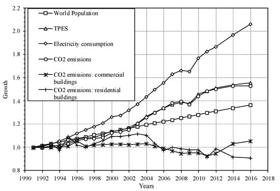
Figure 1.
Global indicators evolution [1]. TPES—Total Primary Energy Supply.
Regarding the period from 2000 to the present, the total energy consumption in the European Union (EU) buildings has not changed significantly. However, in Southern Europe, a growth in the energy demand for cooling was observed [1,2,3]. Thus, the rise in the energy for cooling demand is expected to be about 150% by 2050 (globally) and between 300 and 600% in developing countries [1].
Pursuing a reduction in the energy demand, while maintaining the thermal comfort of the occupants, the continuous research to find new solution, materials and constructive solutions is necessary in the buildings sector [4]. Focusing on the cooling demand and the overheating risk, the use of phase change materials (PCMs) in constructive solutions has attracted the attention of the research community due to their capacity for energy storage [5], which allows the delay of cooling peak load reducing the maximum and minimum indoor air temperature.
Recent researches in this field, particularly aimed at cooling energy reduction focusing on the different systems and strategies incorporating PCM is separated into: microencapsulated PCM inside the material, such as concrete [6,7,8]; Trombe solar wall integrating microencapsulated PCM [9]; gypsum [10,11,12,13]; installed into constructive solutions as an independent layer [14,15]; wallboard and gypsum board [16,17,18]; as a shading device [19]; and macro-encapsulated PCM [20,21,22]. Moreover, in buildings, the use of PCM could be extended to other interior space envelopes [23], such as suspended ceilings [14,24], floors [8,25], windows [19] and active equipment for cooling or heating [26,27].
Passive techniques have attracted several researchers to fully utilizing natural and hybrid ventilation integrated with the use of PCM components and solutions for overheating reduction [28,29]. Regarding cooling performance, Yuekuan Zhou [29] used the night-time ventilation to decrease the indoor air temperature at night and a layer of PCM in the exterior surface of the constructive solution to decrease the peak of indoor temperature at midday. On the other hand, the widespread application of advanced renewable systems with optimal design led to several developments combining PCM solutions and active systems using machine learning, optimisation as well as artificial intelligence in the design phase [30,31,32,33].
Recently, several authors have focused on the study of new strategies to incorporate PCM into composite foams for applications as insulation layers in the buildings. Charles and Mohammed [34] performed a critical review regarding the advances in the incorporation of PCM into the polyurethane foams using different methods as well as the potential and economic benefits regarding these PCM applications in buildings. They highlight that the use of PCM in foam composite is associated to a double benefit of providing a thermal constraint to heat flow as well as a thermoregulation effect [35]. Focusing on the trend regarding the use of PCM into polyurethane foams, Amaral and other researchers [36,37,38] studied the evaluation of thermophysical properties (thermal conductivity) of polyurethane foams with or without microencapsulated PCM in different percentages. In these studies, three different approaches were analysed: the thermal flux meter approach, the guarded hot plate and the transient plane source. Regarding results, they highlight that the use of the microencapsulated PCM in the rigid polyurethane foams leads to an enhanced behaviour of the thermal properties.
Regarding the economic analysis, focusing the PCM application on buildings has been widely discussed by several authors. According to Chan [39], the global application of PCM as a passive constructive solution for buildings has a significant potential of energy-saving; however, this requires high investment cost in PCM materials. Sun et al. [40] performed an economic and energy analysis using the Life Cycle Cost (LCC) based on the payback period for PCM wallboards related to the cooling season. From their findings, for an expected reduction in electric rates, PCM application achieves a minimum payback of 9 years in moderate climates regarding the natural cold energy use. On the other hand, Solgi et al. [41] investigated the use of PCM materials for both heating and cooling reduction by optimal melting points, showing that their incorporation has a great impact on energy-savings. However, PCM materials are not cost effective, leading to huge paybacks periods over 42 years. The present paper presents several optimised strategies for constructive solutions containing PCM in cold-formed steel-framed buildings. Reduction in the overheating rate (total number of hours when indoor temperature is above 26 °C, given as a percentage in one year) was improved either by changing the position of the PCM and by adding a solution containing PCM with different melting points. This paper focuses on the development of an integrated multiscale modelling approach interfacing two linked domains: a combination of different temperature melting values of PCM into the same constructive solution; different possibilities of the PCM position into the same construction solutions. The findings are considered a novel contribution in respect to the multiscale optimised design approach to the definition of solutions containing the incorporation of PCM for overheating rate reduction.
2. Methodology
This work focuses on the building construction envelope solutions incorporating PCM (walls and ceiling) optimisation, to minimise the overheating risk and total heating demand. Thus, a whole building dynamic simulation of a cold-formed steel-framed (low thermal inertia) detached building was performed, with EnergyPlus® 8.7.0 software. EnergyPlus® is highly accredited as a software with the capability to simulate PCMs. Nevertheless, several different approaches to simulate the melting and solidification process have been widespread and can be consulted in [42].
The overheating rate was studied for constant passive parameters applied continuously (considering day or night time) regardless of specific occupation schedules.
The implemented methodology to assess the impact of the PCM incorporation into the building fabric (see Figure 2) is divided into four main steps:
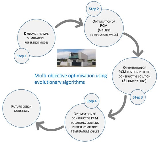
Figure 2.
Methodology framework/outline.
- Step 1
- —Dynamic Thermal Simulation: Reference model
This step starts with the characterization of the building thermal performance considering the constructive solutions applied in the construction (without solutions containing PCM or additional features).
- Step 2
- —Optimisation of PCM (melting temperature value)
This step targets the simulation and optimisation of different peak temperature melting values of the PCM. Combining PCM with different melting temperature values as a discrete parameter was simulated to attain the best scenarios that lead to the lowest annual energy demand and lowest overheating risk rate. For this step, the mechanical ventilation system and night ventilation (free cooling through opening windows) were optimised as well.
Solutions containing PCM were applied and combined in the surfaces with south orientation on the first floor and ceiling to avoid the indoor air temperature stratification effect along the south- and north-orientated surfaces. Results are compared with the reference model (Step 1).
- Step 3
- —Optimisation of the PCM position into constructive solutions (3 approaches)
The procedure defined in Step 3 defines the optimisation premise, including the features of the PCM and the layer position into the building envelope solutions.
The uncertainty of the PCM position into a building construction solution to promote the charging–discharging cycles is an issue. In this step, three situations of the construction solutions incorporating PCM are modelled varying the position of the PCM layer as follows (see Section 5.3):
- -
- (1) Positioned as the most inner surface layer of the construction solution;
- -
- (2) Positioned behind the double gypsum board (interior to the exterior);
- -
- (3) Positioned in the middle of the solution, behind the acoustic layer.
- Step 4
- —Using a multiscale modelling approach interfacing the combination of different temperature melting values of PCM and PCM position into the constructive solution
The influence of incorporation two PCMs solutions into the walls and ceiling, with different melting temperature values, was evaluated.
The best combination of PCM with different melting temperature values was evaluated and optimised for the south-orientated thermal zones. The three possibilities of the PCM position into the construction solutions (defined in Step 3) were simulated in the present step.
Finally, a list of recommendations is provided to aid designers when choosing PCM and placing this unique layer into building solutions, as well as to demystify several issues in the research community.
Figure 2 presents the framework/outline of the proposed simulation.
3. Building Characterization
The building under study is in Aveiro region, at about 5 km from the city centre and 10 km from the Atlantic Ocean, in the northern region of mainland Portugal. The building geometry is composed of a rectangular shape in the plan and consists of a two-story building, constructed using prefabricated cold-formed steel-framed elements (see Figure 3).
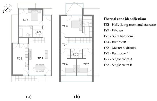
Figure 3.
Building plans: (a) ground floor (b) first floor.
The envelope of the building (see Table 1) is composed of a massive ground floor concrete slab, with 10 cm of thermal insulation positioned underneath. This solution is the support of the cold-formed steel structure and has an Uvalue of 0.32 W m−2 K−1. The exterior walls consist of a thermal insulation layer with 12 cm thickness, assembled with a primary steel structure. Additionally, a second insulation layer (due to acoustic requirements) of 5 cm was positioned after the gypsum plasterboard. This solution has an Uvalue of 0.21 W m−2 K−1. Finally, the flat roof is composed of 15 cm of thermal insulation fixed to a zinc sheeting supported over the main steel structure, and 5 cm of acoustic and thermal insulation over the plasterboard, representing an Uvalue of 0.18 W m−2 K−1. The envelope constructive solutions were analytically calculated following the standard [43] and analysed taking into account the linear thermal bridges following EN ISO 10211 [44].

Table 1.
Case study: general characterization.
Regarding windows solutions, a Solar Heat Gain Coefficient (SHGC) of 0.57 and Uw,installed of 1.72 W m−2 K−1 for the glazing areas to the northeast and Uw,installed of 1.69 W m−2 K−1 to the southwest was used. The entrance door has an Uw,installed of 1.90 W m−2 K−1. The presented values were obtained considering the interface between the glass edge and the frame following the standard ISO 10077 [45], as well as the thermal bridge due to the installation process in agreement with EN ISO 10211 [44].
The building has a treated floor area of 141.6 m2 and the global percentage of glazing is 16.4% in respect to opaque façade area, distributed by a relative percentage of 32.3% with northeast orientation and 58.7% with southwest orientation.
The main properties of the building are detailed in [46] with a schematic view.
4. Dynamic Thermal Simulation Model Definition and Calibration
The building model was drawn using the SketchUp® (Trimble Inc., Sunnyvale, CA, USA) software with a graphical interface (OpenStudio plugin—a registered trademark of the Alliance for Sustainable Energy, U.S.), reproducing the geometry of the model and the thermal zoning division.
The annual thermal behaviour of the building was simulated using EnergyPlus® (managed by the National Renewable Energy Laboratory, U.S.) software considering the conduction transfer function model with a time step considering 6 divisions in one hour. A multi-zone model was defined using eight thermal zones, according to the internal spaces of the building (see thermal zones division in Figure 3).
Regarding the monitoring, thermo-hygrometer sensors were installed in 6 interior zones, to measure the air temperature and relative humidity during the period from 22 October to 21 December with a data acquisition frequency equal to 10 min−1. Exterior dry bulb temperature, relative humidity, solar irradiation and wind speed and direction were also monitored for calibration purposes. Considering that air infiltration has a significant influence on indoor thermal behaviour, a blower door test was also performed. An infiltration of 0.9 h−1 with a pressure difference of 50 Pa was observed, indicating a very airtight building envelope.
Figure 4 depicts the coefficient of determination (r2) for the simulated and real temperatures results. The point cloud obtained reveals a good agreement of temperatures with deviations of ±1 °C.
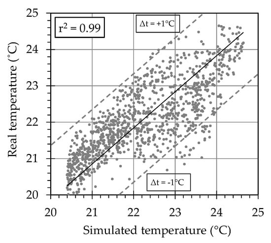
Figure 4.
Coefficient of determination for the best model calibrated.
All data from monitoring were used to calibrate the dynamic model. Thus, the calibration was performed by using the index of coefficient-of-variation of the root mean square error (CV RMSE) between the real building and the numerical model.
A CV RMSE of 3.28 was attained, meaning a good agreement between measured and simulated data, according to ASHRAE, IPMVP and FEMP standards [47,48,49].
Additional features, including real schedules, ventilation system characterization with heat recovery as well as monitoring plots are fully detailed in Oliveira et al. [46].
5. Attained Results and Discussion
5.1. Whole Building Thermal Characterization: Reference Model (Step 1)
The reference building was modelled using an ideal air system for heating, activated at 20 °C using an ACR (air change rate) of 0.6 h−1. The thermal performance of the building was assessed in terms of calculating the accumulated overheating hours over the whole year (when the indoor temperature rises above 26 °C). In the case of cooling, a constant airflow from the outdoor air at a rate of 0.6 h−1 was considered. This ventilation system has no capacity for air-conditioning.
The attained results were 14.32 kWh m−2 a−1 for the total heating demand and 24.39% of overheating rate considering the limit of 26 °C on an annual basis.
Focusing on the overheating issue, TZ7 and TZ8 (thermal zones at the elevated floor with south orientation presented in Figure 3) were chosen due to the fairly high indoor temperatures registered during the summer season. Thus, for these two thermal zones, the annual results for the total heating demand and overheating rate were attained—6.36 kWh m−2 a−1 and 35.20%, respectively. As expected, the heating demand decreased, and the overheating rate increased due to the higher heat gains through the southwest-oriented glazing.
5.2. Thermal Behaviour Improvements Using PCM: Melting Temperature Value Optimisation (Step 2)
The strategy of this step starts with the use of PCM incorporated into the walls and ceiling in thermal zones TZ7 and TZ8. PCM was considered to be applied behind the double plasterboard for both constructive solutions (walls and ceiling). Then, an evolutionary algorithm to operate the EnergyPlus software in the model definition was used for performance assessment of the different solutions incorporating PCM. This evolutionary algorithm is based on the CMA-ES (covariance matrix adaptation evolution strategies) and HDE (hybrid differential evolution) that operates in series, repeating a sequence of generations for each algorithm until the objective function is achieved [50,51].
The goal of this step is the PCM melting temperature value optimisation, combined with the ventilation parameters, using continuous and discrete variables in the optimisation process (see Table 2).
Table 2.
Input parameters.
The nomenclature used for the discrete variables, named by BioPCM® ‘Ma/Qb_c’, are:
- Ma
- —Manufacturer’s internal code for product identification, related to the thermal storage capacity of the material;
- Qb
- —Manufacturer’s internal code for phase change temperature of the product, where b is the phase change temperature value in °C;
- C
- —Thickness of the manufacturer’s product, in m.
Natural ventilation through window opening was computed by the EnergyPlus algorithm depending on the infiltration level, openings aperture and wind intensity and direction.
The optimisation process was run using heating demand and overheating rate as the objective functions to be minimised. Overheating was estimated considering an upper limit of 26 °C and using the Energy Management System (EMS) feature in EnergyPlus to program new outputs. With this optimisation, higher reductions in the overheating rate and a significant reduction in annual heating demand were achieved, when compared to the reference solution. The results observed in Figure 5 contain the Pareto front [52,53], composed of points that are not strictly dominated by any other (black triangles), which represent a set of optimal solutions. The improvement attained concerning the overheating rate and heating demand reductions is remarkable compared with the reference model.
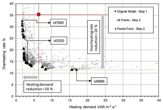
Figure 5.
Pareto front using all simulated results: Steps 1 and 2.
From the set of optimal solutions, three scenarios were chosen according to the following premises: 1—the minimum value of the heating demand; 2—the minimum value of the overheating rate; 3—balanced/trade-off solution between both objective functions (heating demand and overheating rate).
For scenario 2, a melting temperature value below the upper limit of thermal comfort (26 °C), combined with the higher ventilation rate, was chosen.
Concerning the heating demand, a reduction was attained with the PCM optimised to a melting temperature value of 23 °C along with a lower ventilation rate.
Regarding the window opening and operation, the definition of a temperature trigger that can automatically lead to window opening was considered as a good solution to counteract overheating (Table 3). In the presented case, the window was opened when the indoor temperature rose above 23 °C in the best scenario to reduce overheating (id8986).
Table 3.
Parameters results for Step 2.
In addition to the above conclusions, the obtained results reveal better behaviour when the phase change temperature of the PCM is close to the room indoor comfort temperature.
5.3. Thermal Behaviour Improvement: PCM Position Optimisation in the Construction Solution (Step 3)
At this step, the goal is the cumulative improvement of the results attained in Step 2. Thus, the strategy was the optimisation of the PCM position into construction solutions.
Kosny [54] proposes a distribution of the PCM into the constructive solutions to take advantage of the full capacity of the charge–discharge cycles of PCM during a daily amplitude temperature (Figure 6).
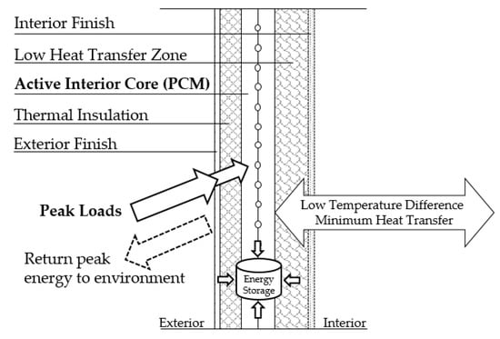
Figure 6.
Constructive solution with enhanced PCM (adapted from [54]).
Thus, to develop this issue, the simulations were carried out considering the PCM layers in different positions (1 to 3) according to Figure 7.
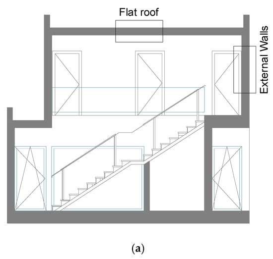
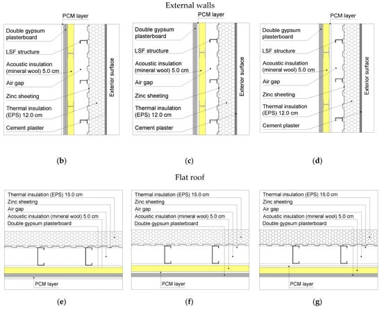
Figure 7.
Constructive solutions details including PCM and positioning into the construction solutions: (a) cross-sections identification; (b,e) position 1: inner surface layer; (c,f) position 2: behind the double gypsum plasterboard; (d,g) position 3: behind the acoustic layer.
To assess the impact and the optimised PCM position, a new set of parameters and strings were added to Table 2 (see Table 4).
Table 4.
New set of parameters and strings.
The objective functions listed in Step 2 were maintained.
Figure 8 shows that the PCM position has a significant impact on overheating reduction of about 2%. Regarding the heating demand, similar results were attained with a small difference of about 1%.
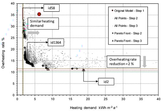
Figure 8.
Pareto fronts and all simulated results: Step 3.
Solely targeting the reduction in the overheating rate, the best solution was attained with BioPCM® M27/Q27_0.011 in position 2 for the walls and BioPCM® M27/Q27_0.011 in position 1 (see Figure 6) for the roof. Thus, the PCM positioning into the construction solution, walls and ceiling is not a straightforward decision. Regarding the scenario with the PCM layer positioned after the acoustic insulation layer (id2), the zone considered to have low heat transfer (Figure 5) was never chosen by the optimiser. Therefore, a detailed analysis was performed changing the PCM only in position 1 and 2, and it was possible to conclude that small differences were attained for the overheating rate reduction (less than 1%). Thus, the use of the PCM layer as the most inner layer is recommended. Additionally, the increase in the wall surface heat coefficient, due to the increase in the air velocity, promotes the PCM charge and discharge process.
5.4. Thermal Behaviour Improvement: PCM Solution Combination (Step 4)
Focusing on the overheating risk and the fact that the use of one type of PCM in some situations during a daily cycle cannot be totally discharged, an additional analysis was carried out, combining two PCMs with different melting temperature values.
To achieve the optimised PCM combination with two different melting temperature values, the parameter related to the partial amount (in thickness) of the PCM employed was conditioned in the optimiser code. Thus, the different thickness of the PCM of each type was defined in the code as input according to the Equation (1):
where:
- = thickness of the chosen PCM (M91 or M51 or M27);
- = thickness of the chosen PCM (M91 or M51 or M27);
- = total thickness of the PCM solution (see Figure 9).
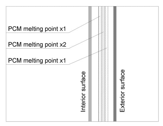 Figure 9. Combination scheme of the PCMs.
The parameter assumes the range of values: ]0.001 m; 0.037 m] for PCM type M91; ]0.001 m; 0.021 m] for PCM type M51; and ]0.001 m; 0.011 m] for PCM type M27 for PCM type M27. Thus, the final constructive solution combines layers of the different PCMs as shown in Figure 9.
Using this formulation, the total thickness of incorporated PCM is always the same for all simulation steps.
The obtained results reveal a better behaviour in terms of heating demand and overheating rate (reducing both) in the case of the use of PCM solutions with different melting temperatures. Thus, a reduction of 3% of the overheating rate was attained compared with the results from Step 3 (Figure 10).
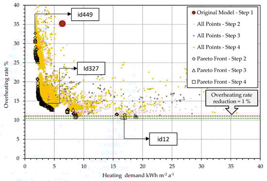
Figure 10.
Pareto fronts and all simulated results: Step 4.
This solution (id12) combines 51% of BioPCM type M91 with a melting temperature of 23 °C and 49% of BioPCM type M91 with a melting temperature of 27 °C.
Regarding the PCM position, in the case of the walls, the best position for the PCM layer is position 2 and for the roof, position 1.
Thus, designers should specify a blend of PCM with melting points closest to the upper limit of the desirable range of temperature, as well as the positioning of the PCM in the inner surface of the habited space.
Despite the small reduction attained using the solution with a combination of different PCMs, the strategy to combine PCM with different melting temperature values can potentiate a more effective impact of the use of PCM to compensate situations where the discharging process is not complete, as is the case on hotter days.
6. Final Comments
The goal of this study was the overheating issue mitigation in buildings, which typically occurs in those with low thermal inertia, focusing on the constructive solutions optimisations incorporating PCM. Thus, different PCM solutions were modelled, and a step-by-step parametric study was carried out to optimise the PCM melting temperature, positioning and potential combination of different PCMs into walls and ceilings with south orientation. In addition to the parametric analysis, a novel integrated multiscale modelling approach was developed to quantify the combined effect of the use of different melting points with different positioning of the PCM into construction solutions.
Regarding the use of PCM into lightweight construction solutions, five mains aspects are highlighted:
- -
- The completely charge–discharge cycles of the PCM is only possible considering an effective compromise with the PCM melting temperature and ventilation rate selection;
- -
- The selection of the melting temperature of the PCM is crucial to fully take advantage of the PCM latent heat capacity (charge–discharge on a daily cycle);
- -
- The PCM position into construction solutions is of paramount importance, since charging and discharging is more effective when PCM is positioned as the most superficial inner layer;
- -
- Combining constructive solutions incorporating PCM with different melting temperatures is an effective strategy to reduce overheating risk when compared with constructive solutions containing solely one type of PCM;
- -
- The results reveal that the methodology should be incentivized to be used by the designers, combining different amounts of PCM with different melting point temperature values into the constructive solutions using the PCM as the innermost surface of the envelope walls.
In sum, fairly good results in terms of heating energy demand and overheating rate reductions prove that the use of PCM solutions in such construction typologies is suitable to compensate for the lack of thermal inertia of cold-formed steel-framed buildings. On the other hand, for further developments, a Life Cycle Assessment (LCA) and Life Cycle Cost (LCC) analysis is strongly recommended to identify the economic feasibility of the PCM approach.
Author Contributions
Conceptualization, A.F., R.O., R.V., A.S. and F.R.; methodology, A.F., R.O. and R.V.; software, A.F. and R.O.; validation, A.F. and R.O.; formal analysis, A.F. and R.O.; investigation, A.F. and R.O.; resources, R.O., M.F. and A.S.; data curation, A.F. and R.O.; writing—original draft preparation, A.F. and R.O.; writing—review and editing, A.F., R.O., R.V., A.S. and F.R.; visualization, A.F., R.O., R.V., A.S. and F.R.; supervision, A.F., A.S.; project administration, A.S.; funding acquisition, A.S. All authors have read and agreed to the published version of the manuscript.
Funding
This research was funded by the project THERMACORE—Performance of a wall or slab with a thermally active core in buildings in Portugal, POCI-01-0145-FEDER-030364, with the financial support of FCT—Fundação para a Ciência e Tecnologia/MCTES.
Acknowledgments
The authors would like to thank the project THERMACORE—POCI-01-0145-FEDER-030364.
Conflicts of Interest
The authors declare no conflict of interest.
References
- International Energy Agency. Energy Efficiency 2018 Analysis and Outlooks to 2040; International Energy Agency: Paris, France, 2018. [Google Scholar]
- Eurostat. Energy Statistics—Residential Consumption. Eurostat. European Commission. 2011. Available online: http://epp.eurostat.ecs.europa.eu/ (accessed on 10 July 2020).
- Balaras, C.A.; Grossman, G.; Henning, H.-M.; Ferreira, C.A.I.; Podesser, E.; Wang, L.; Wiemken, E. Solar air conditioning in Europe—An overview. Renew. Sustain. Energy Rev. 2007, 11, 299–314. [Google Scholar] [CrossRef]
- Torgal, F.P.; Jalali, S. Eco-Efficient Construction and Building Materials; Springer: Berlin/Heidelberg, Germany, 2011. [Google Scholar]
- De Gracia, A. Dynamic building envelope with PCM for cooling purposes—Proof of concept. Appl. Energy 2019, 235, 1245–1253. [Google Scholar] [CrossRef]
- Cabeza, L.F.; Castellón, C.; Nogués, M.; Medrano, M.; Leppers, R.; Zubillaga, O. Use of microencapsulated PCM in concrete walls for energy savings. Energy Build. 2007, 39, 113–119. [Google Scholar] [CrossRef]
- Bahrar, M.; Djamai, Z.I.; El Mankibi, M.; Larbi, A.S.; Salvia, M. Numerical and experimental study on the use of microencapsulated phase change materials (PCMs) in textile reinforced concrete panels for energy storage. Sustain. Cities Soc. 2018, 41, 455–468. [Google Scholar] [CrossRef]
- Figueiredo, A.; Lapa, J.A.M.; Vicente, R.; Cardoso, C. Mechanical and thermal characterization of concrete with incorporation of microencapsulated PCM for applications in thermally activated slabs. Constr. Build. Mater. 2016, 112, 639–647. [Google Scholar] [CrossRef]
- Leang, E.; Tittelein, P.; Zalewski, L.; Lassue, S. Numerical study of a composite Trombe solar wall integrating microencapsulated PCM. Energy Procedia 2017, 122, 1009–1014. [Google Scholar] [CrossRef]
- Schossig, P.; Henning, H.-M.; Gschwander, S.; Haussmann, T. Micro-encapsulated phase-change materials integrated into construction materials. Sol. Energy Mater. Sol. Cells 2005, 89, 297–306. [Google Scholar] [CrossRef]
- Serrano, S.; Barreneche, C.; Fernandez, A.I.; Farid, M.M.; Cabeza, L. Composite gypsum containing fatty-ester PCM to be used as constructive system: Thermophysical characterization of two shape-stabilized formulations. Energy Build. 2015, 86, 190–193. [Google Scholar] [CrossRef]
- Jeong, S.-G.; Wi, S.; Chang, S.J.; Lee, J.; Kim, S. An experimental study on applying organic PCMs to gypsum-cement board for improving thermal performance of buildings in different climates. Energy Build. 2019, 190, 183–194. [Google Scholar] [CrossRef]
- Li, C.; Yu, H.; Song, Y. Experimental investigation of thermal performance of microencapsulated PCM-contained wallboard by two measurement modes. Energy Build. 2019, 184, 34–43. [Google Scholar] [CrossRef]
- Figueiredo, A.; Vicente, R.; Lapa, J.; Cardoso, C.; Rodrigues, F.; Kämpf, J. Indoor thermal comfort assessment using different constructive solutions incorporating PCM. Appl. Energy 2017, 208, 1208–1221. [Google Scholar] [CrossRef]
- Vicente, R.; Silva, T. Brick masonry walls with PCM macrocapsules: An experimental approach. Appl. Therm. Eng. 2014, 67, 24–34. [Google Scholar] [CrossRef]
- Scalat, S.; Banu, D.; Hawes, D.; Parish, J.; Haghighata, F.; Feldman, D. Full scale thermal testing of latent heat storage in wallboard. Sol. Energy Mater. Sol. Cells 1996, 44, 49–61. [Google Scholar] [CrossRef]
- Chhugani, B.; Klinker, F.; Weinlaeder, H.; Reim, M. Energetic performance of two different PCM wallboards and their regeneration behavior in office rooms. Energy Procedia 2017, 122, 625–630. [Google Scholar] [CrossRef]
- Xie, J.; Wang, W.; Liu, J.; Pan, S. Thermal performance analysis of PCM wallboards for building application based on numerical simulation. Sol. Energy 2018, 162, 533–540. [Google Scholar] [CrossRef]
- Silva, T.; Vicente, R.; Amaral, C.; Figueiredo, A. Thermal performance of a window shutter containing PCM: Numerical validation and experimental analysis. Appl. Energy 2016, 179, 64–84. [Google Scholar] [CrossRef]
- Navarro, L.; De Gracia, A.; Castell, A.; Álvarez, S.; Cabeza, L. Design of a Prefabricated Concrete Slab with PCM Inside the Hollows. Energy Procedia 2014, 57, 2324–2332. [Google Scholar] [CrossRef]
- De Gracia, A.; Navarro, L.; Castell, A.; Cabeza, L. Numerical study on the thermal performance of a ventilated facade with PCM. Appl. Therm. Eng. 2013, 61, 372–380. [Google Scholar] [CrossRef]
- Navarro, L.; De Gracia, A.; Castell, A.; Álvarez, S.; Cabeza, L. PCM incorporation in a concrete core slab as a thermal storage and supply system: Proof of concept. Energy Build. 2015, 103, 70–82. [Google Scholar] [CrossRef]
- Kuznik, F.; Virgone, J.; Johannes, K. In-situ study of thermal comfort enhancement in a renovated building equipped with phase change material wallboard. Renew. Energy 2011, 36, 1458–1462. [Google Scholar] [CrossRef]
- Alqallaf, H.J.; Alawadhi, E.M. Concrete roof with cylindrical holes containing PCM to reduce the heat gain. Energy Build. 2013, 61, 73–80. [Google Scholar] [CrossRef]
- Royon, L.; Karim, L.; Bontemps, A. Thermal energy storage and release of a new component with PCM for integration in floors for thermal management of buildings. Energy Build. 2013, 63, 29–35. [Google Scholar] [CrossRef]
- Hu, W.; Song, M.; Jiang, Y.; Yao, Y.; Gao, Y. A modeling study on the heat storage and release characteristics of a phase change material based double-spiral coiled heat exchanger in an air source heat pump for defrosting. Appl. Energy 2019, 236, 877–892. [Google Scholar] [CrossRef]
- Mengjie, S.; Niu, F.; Mao, N.; Hu, Y.; Deng, S. Review on building energy performance improvement using phase change materials. Energy Build. 2018, 158, 776–793. [Google Scholar] [CrossRef]
- Zhou, Y.; Zheng, S. Multi-level uncertainty optimisation on phase change materials integrated renewable systems with hybrid ventilations and active cooling. Energy 2020, 202, 117747. [Google Scholar] [CrossRef]
- Zhou, Y.; Zheng, S.; Zhang, G. Study on the energy performance enhancement of a new PCMs integrated hybrid system with the active cooling and hybrid ventilations. Energy 2019, 179, 111–128. [Google Scholar] [CrossRef]
- Zhou, Y.; Zheng, S.; Zhang, G. Machine learning-based optimal design of a phase change material integrated renewable system with on-site PV, radiative cooling and hybrid ventilations—Study of modelling and application in five climatic regions. Energy 2020, 192, 116608. [Google Scholar] [CrossRef]
- Zhou, Y.; Zheng, S.; Zhang, G. Machine-learning based study on the on-site renewable electrical performance of an optimal hybrid PCMs integrated renewable system with high-level parameters’ uncertainties. Renew. Energy 2020, 151, 403–418. [Google Scholar] [CrossRef]
- Zhou, Y.; Zheng, S.; Liu, Z.; Wen, T.; Ding, Z.; Yan, J.; Zhang, G. Passive and active phase change materials integrated building energy systems with advanced machine-learning based climate-adaptive designs, intelligent operations, uncertainty-based analysis and optimisations: A state-of-the-art review. Renew. Sustain. Energy Rev. 2020, 130, 109889. [Google Scholar] [CrossRef]
- Zhou, Y.; Zheng, S.; Zhang, G. Artificial neural network based multivariable optimization of a hybrid system integrated with phase change materials, active cooling and hybrid ventilations. Energy Convers. Manag. 2019, 197. [Google Scholar] [CrossRef]
- Ikutegbe, C.A.; Farid, M.M. Application of phase change material foam composites in the built environment: A critical review. Renew. Sustain. Energy Rev. 2020, 131, 110008. [Google Scholar] [CrossRef]
- Jelle, B.P. Nano-based thermal insulation for energy-efficient buildings. In Start-Up Creation: The Smart Eco-Efficient Built Environment; Elsevier Science & Technology: Cambridge, UK, 2016. [Google Scholar]
- Amaral, C.; Vicente, R.; Ferreira, V.; Silva, T. Polyurethane foams with microencapsulated phase change material: Comparative analysis of thermal conductivity characterization approaches. Energy Build. 2017, 153, 392–402. [Google Scholar] [CrossRef]
- Amaral, C.; Vicente, R.; Eisenblätter, J.; Marques, P.A.A.P. Thermal characterization of polyurethane foams with phase change material. Ciênc. Tecnol. Mater. 2017, 29, 1–7. [Google Scholar] [CrossRef]
- Amaral, C.; Pinto, S.; Silva, T.; Mohseni, F.; Amaral, J.; Marques, P.; Barros-Timmons, A.; Vicente, R. Development of polyurethane foam incorporating phase change material for thermal energy storage. J. Energy Storage 2020, 28, 101177. [Google Scholar] [CrossRef]
- Chan, A.L.S. Energy and environmental performance of building faç ades integrated with phase change material in subtropical Hong Kong. Energy Build. 2011, 43, 2947–2955. [Google Scholar] [CrossRef]
- Sun, X.; Zhang, Q.; Medina, M.A.; Lee, K.O. Energy and economic analysis of a building enclosure outfitted with a phase change material board (PCMB). Energy Convers. Manag. 2014, 83, 73–78. [Google Scholar] [CrossRef]
- Solgi, E.; Memarian, S.; Moud, G.N. Financial viability of PCMs in countries with low energy cost: A case study of different climates in Iran. Energy Build. 2018, 173, 128–137. [Google Scholar] [CrossRef]
- Ehms, J.H.N.; Oliveski, R.D.C.; Rocha, L.; Biserni, C.; Garai, M. Fixed Grid Numerical Models for Solidification and Melting of Phase Change Materials (PCMs). Appl. Sci. 2019, 9, 4334. [Google Scholar] [CrossRef]
- ISO. ISO 6946, Building Components and Building Elements—Thermal Resistance and Thermal Transmittance—Calculation Method; International Organization for Standardization: Geneva, Switzerland, 2007. [Google Scholar]
- International Organization for Standardization. “ISO 10211”, Thermal Bridges in Building Construction—Heat Flows and Surface Temperatures—Detailed Calculations; International Organization for Standardization: Geneva, Switzerland, 2007. [Google Scholar]
- ISO. Thermal Performance of Windows, Doors and Shutters—Calculation of Thermal Transmittance ISO; 10077-1; International Organization for Standardization: Geneva, Switzerland, 2006. [Google Scholar]
- Oliveira, R.; Figueiredo, A.; Vicente, R.; Almeida, R.M. Multi-Objective Optimisation of the Energy Performance of Lightweight Constructions Combining Evolutionary Algorithms and Life Cycle Cost. Energies 2018, 11, 1863. [Google Scholar] [CrossRef]
- IPMVP. International Performance Measurement and Verification Protocol–Concepts and Options for Determining Energy and Water Savings; International Performance Measurement and Verification Protocol Committee: Washington, DC, USA, 2002; Volume 1. [Google Scholar]
- Harmer, L.C.; Henze, G.P. Using calibrated energy models for building commissioning and load prediction. Energy Build. 2015, 92, 204–215. [Google Scholar] [CrossRef]
- FEMP. M&V Guidelines: Measurement and Verification for Federal Energy Projects Version 3.0; Federal Energy Management Program; US Department of Energy: Washington, DC, USA, 2008.
- Kämpf, J.H.; Robinson, D. A hybrid CMA-ES and HDE optimisation algorithm with application to solar energy potential. Appl. Soft Comput. 2009, 9, 738–745. [Google Scholar] [CrossRef]
- Kämpf, J.H.; Robinson, D. Optimisation of building form for solar energy utilisation using constrained evolutionary algorithms. Energy Build. 2010, 42, 807–814. [Google Scholar] [CrossRef]
- Dalbem, R.; Da Cunha, E.G.; Vicente, R.; Figueiredo, A.; Oliveira, R.; Da Silva, A.C.S.B. Optimisation of a social housing for south of Brazil: From basic performance standard to passive house concept. Energy 2019, 167, 1278–1296. [Google Scholar] [CrossRef]
- Ou, J.; Zheng, J.; Ruan, G.; Hu, Y.; Zou, J.; Li, M.; Yang, S.; Tan, X. A pareto-based evolutionary algorithm using decomposition and truncation for dynamic multi-objective optimization. Appl. Soft Comput. 2019, 85, 105673. [Google Scholar] [CrossRef]
- Kosny, J.; Kossecka, E.; Brzezinski, A.; Tleoubaev, A.; Yarbrough, D.W. Dynamic thermal performance analysis of fiber insulations containing bio-based phase change materials (PCMs). Energy Build. 2012, 52, 122–131. [Google Scholar] [CrossRef]

Publisher’s Note: MDPI stays neutral with regard to jurisdictional claims in published maps and institutional affiliations. |
© 2020 by the authors. Licensee MDPI, Basel, Switzerland. This article is an open access article distributed under the terms and conditions of the Creative Commons Attribution (CC BY) license (http://creativecommons.org/licenses/by/4.0/).