Article

Identification of Multiple Local Damage to an Offshore Jacket Substructure Using a Novel Strain Expansion–Reduction Approach

1
Department of Engineering Science and Ocean Engineering, National Taiwan University, Taipei 10617, Taiwan
2
Ship and Ocean Industries R&D Center, New Taipei City 251401, Taiwan
*
Author to whom correspondence should be addressed.
Appl. Sci. 2020, 10(22), 7991; https://doi.org/10.3390/app10227991
Submission received: 14 October 2020 / Revised: 5 November 2020 / Accepted: 8 November 2020 / Published: 11 November 2020
(This article belongs to the Special Issue Nondestructive Testing (NDT): Volume II)

Abstract

:
Modal parameter monitoring is a widely used structural health monitoring method. However, among other limitations, this method cannot effectively identify slight damage under ambient conditions. This study proposed a novel strain expansion–reduction approach for identifying damage. To verify the feasibility of the proposed method, we numerically and experimentally tested the method using a rigid acrylic frame. The frame was artificially damaged at various depths to reflect various damage scenarios. The increase in the damage index provided an accurate estimation of damage severity. For the case with merely 0.5% damage zone in one slat, the index is increased by 259% of the intact case. When the damage zone was doubled, the index increases significantly by 467% of the intact case, demonstrating excellent sensitivity of the proposed method. To guarantee practical use, the numerical model of the proposed method was applied to an offshore wind turbine jacket substructure and successfully identified multiple damage sites and the damage severity with extremely high (>10) damage index.

1. Introduction

Structural health monitoring (SHM) is a multidisciplinary field combining sensor technology, signal processing, and statistical analysis. SHM involves continuously monitoring structural health, identifying structural damage at an early stage, assessing structural performance in real time, preventing catastrophic failure through safety warnings, and providing critical information for planning and maintenance. The SHM technique has been used in civil engineering and aviation for many years. In the late 1970s, the aerospace community began to investigate vibration-based damage identification methods [1]. The numerical analysis model was updated using modal parameters measured by comparing damaged and intact structures. The method quantified damage in terms of the change in stiffness [2]; however, applying the method in practice is inconvenient because of the considerable computation involved. Since the 1980s, the civil engineering community has continued to study vibration-based damage identification in bridges and buildings [3,4] through changes in modal parameters such as the natural frequency, damping ratio, and vibration mode. During the same period, the oil and gas industry developed vibration-based damage identification technology and applied it to offshore oil industries [5]. Modal parameter monitoring is a widely used health monitoring method [6,7,8,9,10]. However, severe damage induced in the structure alters the global mode shapes, which may result in inaccurate damage prediction. The higher-order derivatives of the mode shapes of the structure can provide crucial information and are sensitive to local damage [11]. However, a structure requires high energy to become into its higher modes; it cannot be excited under ambient conditions.
Modal parameter monitoring is a critical method to monitoring support and rotor structures in offshore wind turbine (OWT) structures [10,12]. Modal parameter monitoring reveals the overall condition of supporting structures; therefore, local damage in support structures cannot be identified accurately. However, damage typically starts from the joints in the support structure, and the local damage expands gradually to affect the entire structure.
Several reduction–expansion approaches for damage detection have been proposed. Expansion techniques have been commonly used for modal vectors to provide augmented data for correlation studies, model updating, and other applications. Conventionally, researchers have used Guyan condensation [13], dynamic condensation [14], the system equivalent reduction expansion process (SEREP) [15], and the improved reduced system [16]. These approaches have been commonly used for reduction–expansion purposes. Researchers have used these approaches to expand real-time operating data. Chipman and Avitabile [17] used the SEREP to expand real-time operating data measured using accelerometers to predict the response of structures. Baqersad et al. [18] used the SEREP to expand the displacement response on a rotating structure and then calculated the strain response of the structure. Baqersad and Bharadwaj [19] developed a novel strain expansion-reduction (SER) approach based on the strain mode shapes of a structure to accurately predict the dynamic strain.
To evaluate the feasibility of damage identification approaches, frame structures were widely employed for investigation using experimental testing and Finite Element (FE) model validation. Yu et al. [20] adopted three kinds of frame structures to evaluate the efficiency of their FE model-updating technique. Betti et al. [21] employed a genetic algorithm to express identified stiffness reduction as the damage parameters, and experimental results were compared with the results of the optimization algorithm to verify the ability of their approach. In addition, jacket structure or substructures were adopted to evaluate the practical applications of damage identification approaches. Han et al. [22] used a curvature method to perform the damage simulation, and the method was applied to a derrick steel structure to verify feasibility of the proposal. Guo et al. [23] proposed the approach using measured results and artificial intelligence neural networks to present a damage identification procedure applicable to offshore jacket platforms.
In this study, we proposed a novel local damage identification technique that uses the SER approach under ambient conditions. The method was experimentally and numerically verified on an acrylic frame structure, which comprised a cracked beam [24]. Additionally, an OWT jacket substructure was used for numerical verification of the ability of the method to detect multiple damage sites and the severity of damage. The results indicated that the proposed damage identification method can effectively identify multiple damage sites and the severity of damage.

2. Methods

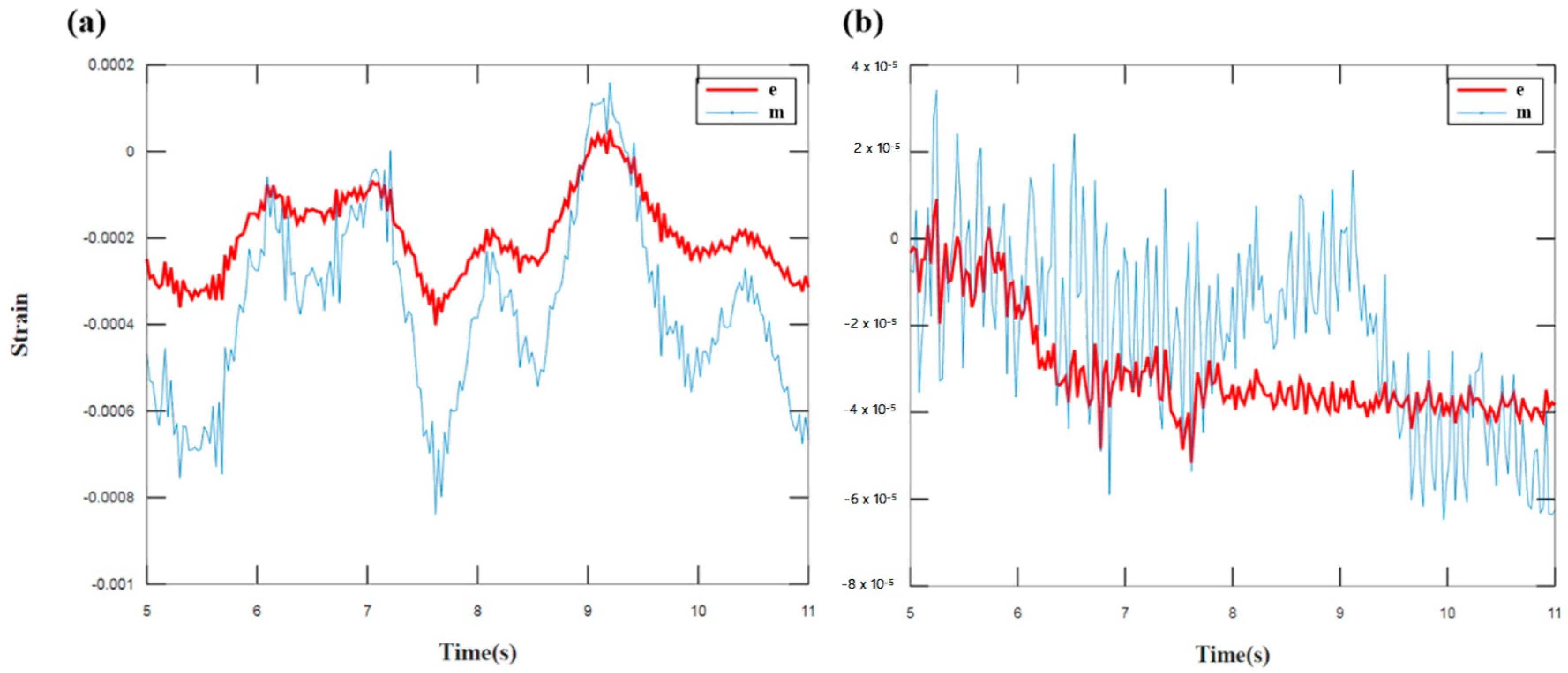
2.1. Theory of the SER Approach

Modal reduction and expansion approaches have been conventionally used in modal analysis for validation and correlation. The SEREP is an approach in which the displacement mode shapes of a structure are employed and a transfer matrix is found using least-square minimization. The method can be used to expand or reduce (the inverse of the matrix) data. In this study, we expanded this approach and used strain mode shapes to develop a transformation matrix for reducing and expanding strain.
To extract the equations for strain mode shapes, we first focused on displacement mode shapes. Equation (1) presents the basic expression of modal analysis. This theory states that the response of a structure to excitations is a linear combination of mode shapes.
{ X n } = [ ϕ n ] { P } ,
where [ ϕ n ] and { X n } represent the displacement mode shapes and displacement response, respectively, of the structure at the full set degrees of freedom (DOFs), and {P} denotes the contribution of each mode to the system’s response. A similar equation for strain response is expressed as follows:
{ ε n } = [ V n ] { P } ,
where [ V n ] denotes the full-space strain mode shapes of the system and { ε n } is the full-field strain response of the structure. The full set of DOFs can be expressed as a combination of active a and deleted d DOFs. Active degrees of freedom are those included in the limited set of measurements as follows:
{ ε n } = { ε a ε d } .
Combining (2) and (3), we obtain the following expression:
{ ε a ε d } = [ V n ] { P } = [ V a V d ] { P } ,
where V a and V d are the strain mode shapes of the structure for the active and deleted DOFs. For the active DOFs, (4) can be expressed as follows:
{ ε a } = [ V a ] { P } .
There are more unknowns in (5) than there are equations. Therefore, (5) should be solved using the generalized inverse method. In the generalized inverse method, these equations are solved using the least squares approach. Premultiplying both sides of (5) by [ V a ] T results in the following:
[ V a ] T { ε a } = [ V a ] T [ V a ] { P } .
Premultiplying (6) by ( [ V a ] T [ V a ] ) 1 , we obtain
( [ V a ] T [ V a ] ) 1 [ V a ] T { ε a } = ( [ V a ] T [ V a ] ) 1 [ V a ] T [ V a ] { P } .
Equation (7) can be expressed as follows:
{ P } = ( [ V a ] T [ V a ] ) 1 [ V a ] T { ε a } ,
{ P } = [ V a ] g { ε a } ,
where g refers to the generalized inverse of the matrix. To determine the full-space response, we substitute {P} from (9) into (2) to obtain
{ ε n } = [ V n ] [ V a ] g { ε a } .
Using (10), the following transformation matrix for the SER approach is formed:
[ T ] = [ V n ] [ V a ] g .
Therefore, (11) can be used to expand real-time operating strain data measured using strain gauges {RTO S a } in the expanded (full-space) real-time operating data {RTO S n }.
{ RTO S n } = [ T ] { RTO S a }
In the proposed technique, the strain mode shapes of the structure are obtained using the structure’s finite element model.

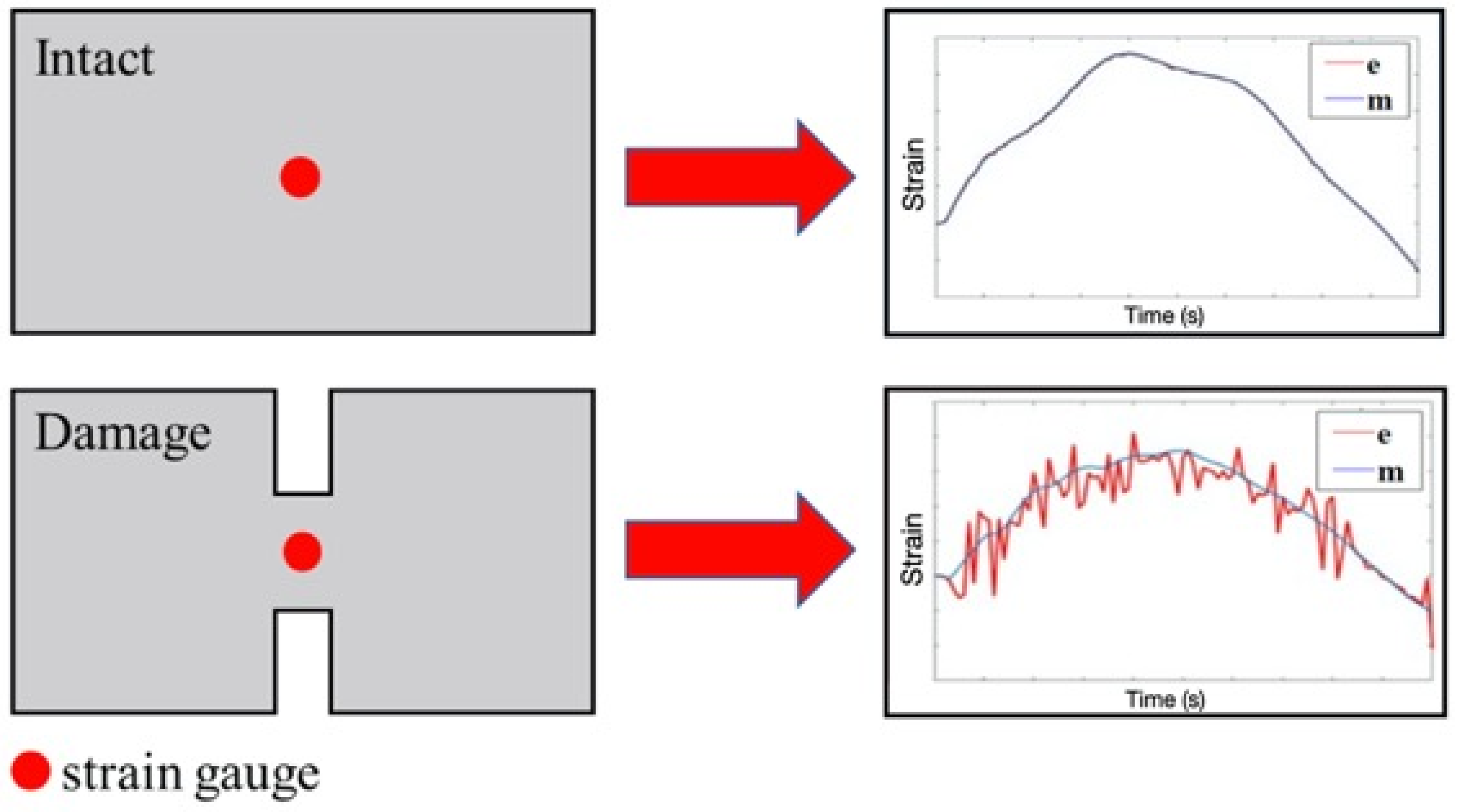
2.2. Damage Identification Approach
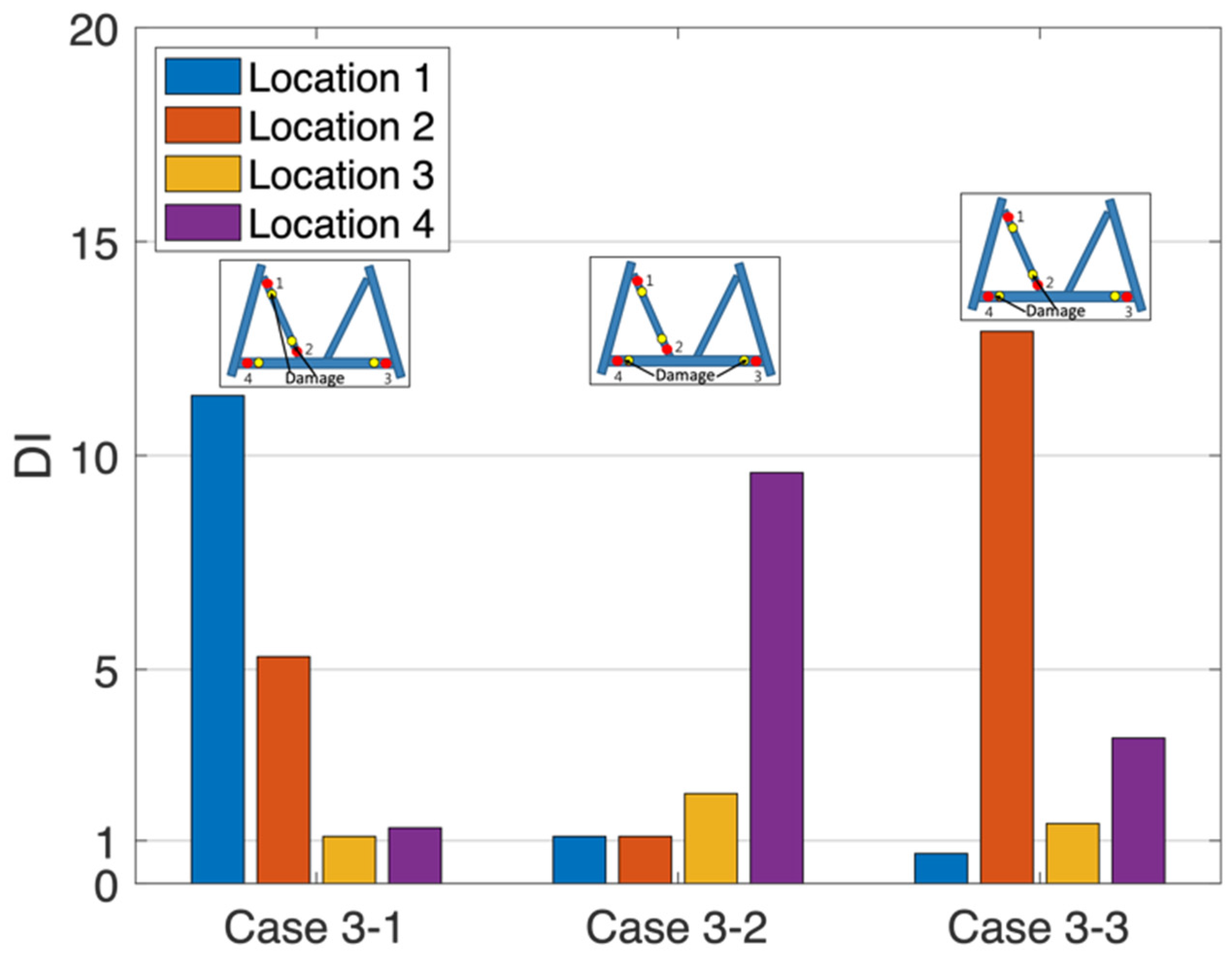
In this study, the proposed damage identification approach was investigated experimentally and numerically. In Figure 1, a schematic of the approach, “e” and “m” denote the expanded strain and measured strain. When the structure is intact, the calculated expanded strain is equal to the measured strain at the same location. However, when the structure is damaged, the expanded strain differs from the measured strain at the same position. This study used these differences to identify damage and employed the degree of difference to determine damage severity.

2.3. Damage Index

To quantify the difference between the expanded and measured strains, we define a quantitative index D as follows:
D = 1 n | m 2 e 2 | A v g ( e 2 )
where m is the measured strain, e is the expanded strain, and n is the number of data points of the time-domain strain. The difference between the two sets of signals can be quantified through D . The larger the value of D , the greater the difference. Although the structure may be healthy, the measured and expanded strains differ from each other slightly. The index D can be calculated using (13) and D 0 is defined as if the structure is healthy. The damage index ( D I ) under different degrees of damage is calculated using the following equation:
D I = D D 0
where D 0 is the D in the health situation. We investigated damage through an increase in the D I and then quantified the destruction level.

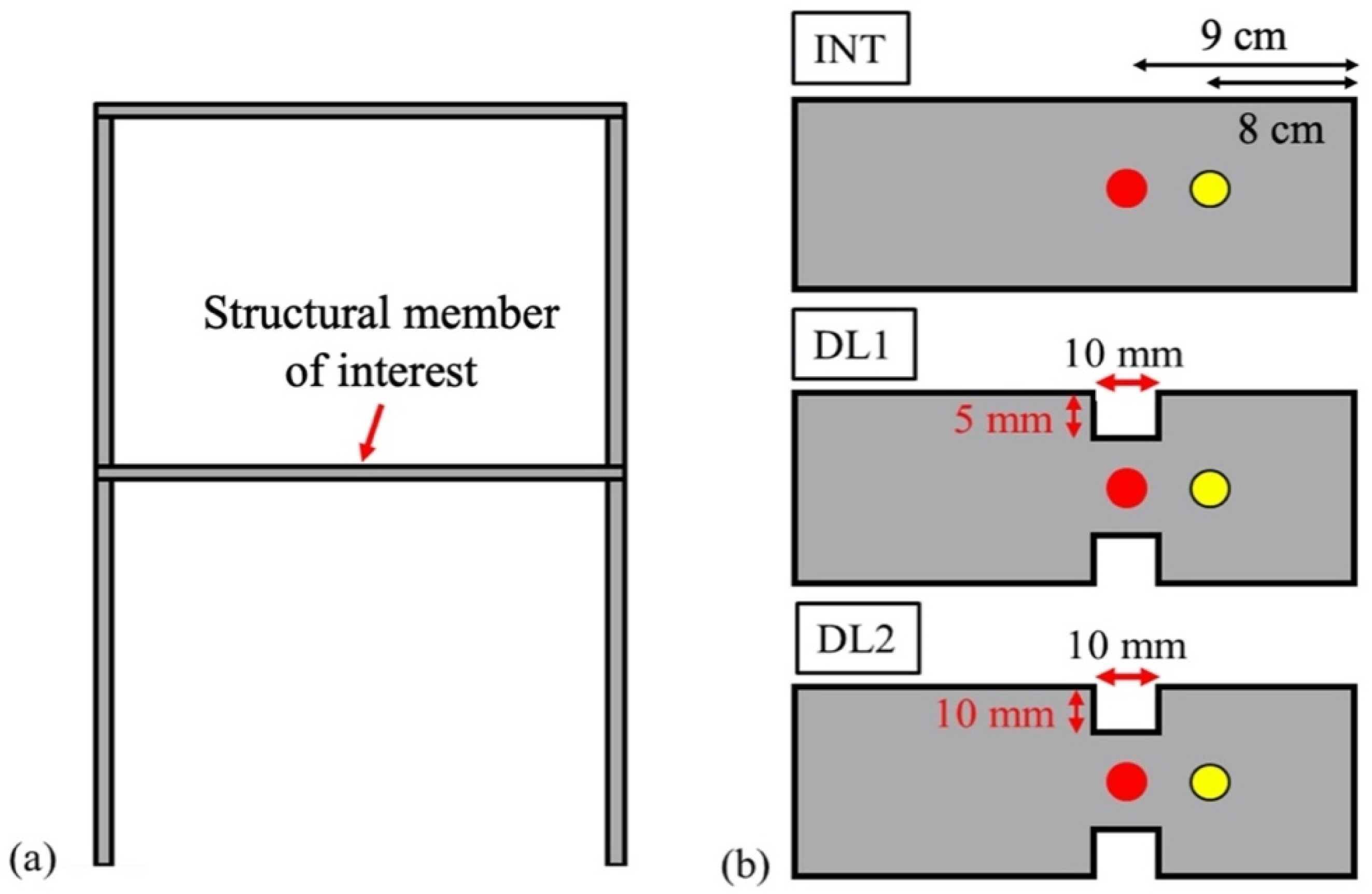
2.4. Validation Model

2.4.1. Numerical Model

An acrylic rigid frame with beam elements consisting of 20,760 elements and 20,767 nodes was modeled in the commercial finite element software Abaqus. For the purpose of validation, we assumed nearly identical, to our best, geometric and material properties between the numerical model and experimental setup. A geometric model of the frame (Figure 2a) included six 400 mm × 50 mm × 5 mm acrylic slats fastened with stainless steel joints. The bottom of the frame was assumed fixed. The material properties of the acrylic and stainless steel included the following: Young’s modulus E = 2.74 and 200 GPa, mass density ρ = 1190 and 7930 kg/m3, and Poisson’s ratio ν = 0.32 and 0.247. To emulate the scenarios of damage and no damage, the horizontal middle section was categorized into three types of slats (Figure 2b), namely intact (INT), mildly (DL1) and severely (DL2) damaged structures, indicated by no cracks and cracks of 5 mm and 10 mm in depth, respectively.
Modal dynamic analysis was then performed on the model by applying a horizontal impact force (representing a hammer shock applied on the structure over a short time period) of 1 N at the top right corner of the frame to obtain the strain (node data). Strain data were calculated at the yellow and red points in Figure 2b, which were 8 and 9 cm away from the right boundary, respectively. Strain data obtained at the red points, defined as expanded points, were expanded to extract full-field strain over the entire frame by using the transformed matrix in (11). Then, D 0 and D were obtained by comparing the data at the expanded point and corresponding measured data at the yellow point, which was defined as the measured point in (13). Furthermore, the D I in the DL1 and DL2 scenarios were obtained using (14).

2.4.2. Experimental Setup

The acrylic rigid frame was measured to experimentally validate the damage identification method. The test frame was excited using an impact hammer (PCB-086C03), and its vibration responses were measured by attaching two uniaxial strain gauges with 5.0 % for strain limits, 2.10 ± 1.0% for gage factor at normal temperature and resistance 120 Ω ± 0.2% (KYOWA-KFGS-5-350-C1-11-L3M3R). Similar to the process of numerical calculation, the strain gauges were mounted at the yellow and red points, which were 8 and 9 cm away from the right boundary, respectively (Figure 2b), and connected to a data acquisition system with the noise of 50 μVrms at maximum sample rate (NI-9234) to measure the time-domain strain response. The full-field strain at the expanded points was obtained using the transformation matrix. Then, the full-field strain was compared with the measured strain to obtain D , and furthermore, D I .

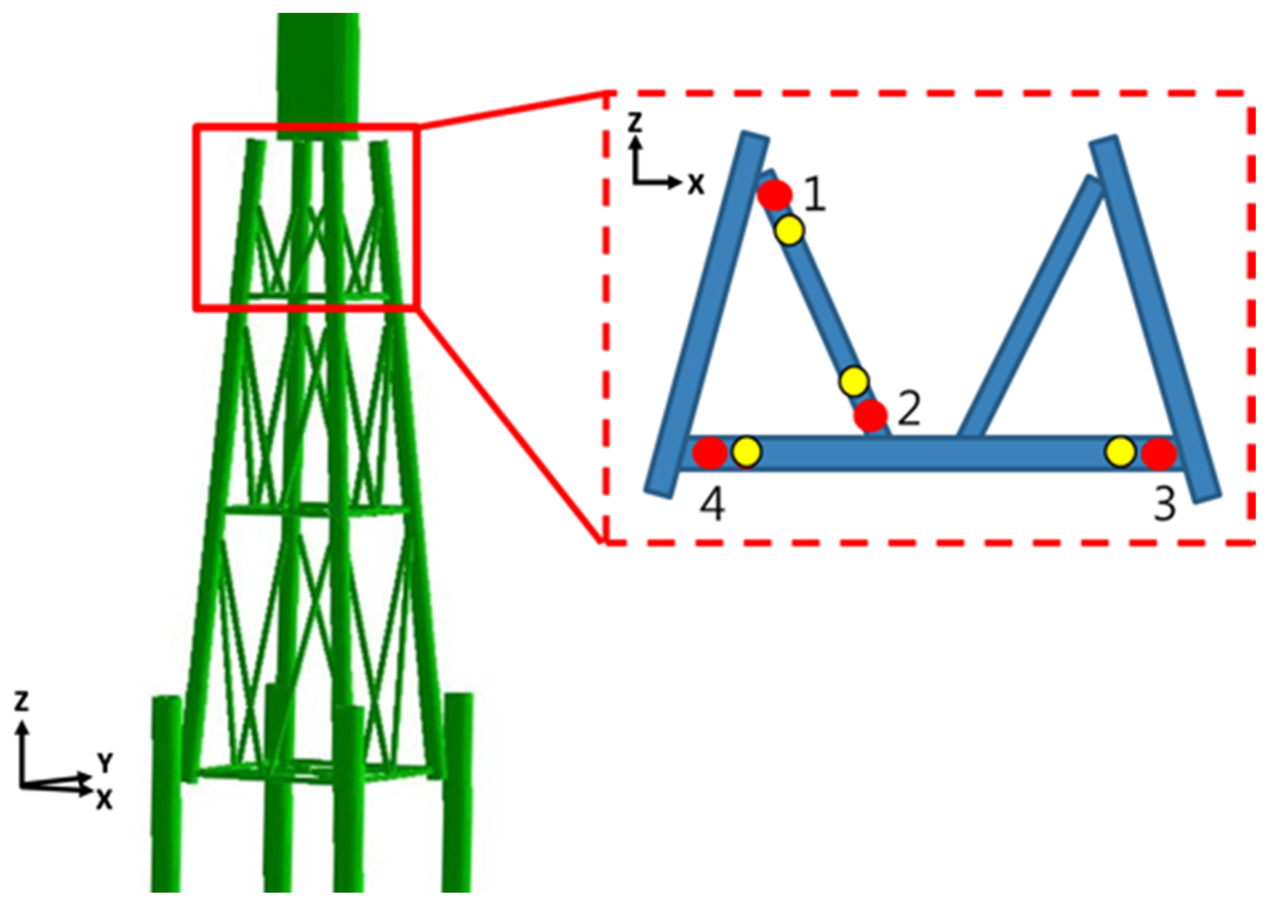
2.4.3. Model for Multiple Damage Site Identification and Damage Scenarios

Multiple damage site identification was numerically investigated using a fixed K-type jacket substructure of an OWT designed by the Fuhai Offshore Wind Farm for a water depth of 23 m. The parameters of the wind turbine in the preliminary design stage were as follows: 3.6 MW rated power output, 120 m diameter of the rotor, 3 m/s cut-in wind speed, 25 m/s cut-out wind speed, 12 m/s nominal wind speed, 68.39 m tower height, and 39.22 m jacket height [25]. The model included a tower with a rotor nacelle assembly of simplified mass on the top of the tower and a jacket substructure that was rooted on four piles, with which the interaction with the soil was reproduced using nonlinear elastic spring connectors. The aerodynamic forces acting on the wind turbine were calculated, and the equivalent load was then applied to the top of the wind tower as a concentrated force in the structural finite element model. Only the x and y components were considered; the z component was neglected because the tilt angle was only 5°. The bending moment at the root of a rotor blade was assumed to be in balance because there were three blades.
For the load combination, it was simply assumed that the wind, wave, and current loads acted in the same horizontal direction and that the resultant forces and moment were solely in-plane. Gust wind speed, significant wave height, wave period, and current speed of 70 m/s, 14.88 m, 12.47 s, and 1.4 m/s, respectively, were considered the extreme condition [26]. The four locations in the first layer (Figure 3) were investigated on the basis of the pipe damage scenarios (Table 1) and severity (Table 2) in the locations of cases.

3. Results and Discussion

3.1. Validation

3.1.1. Numerical Results

Figure 4a shows that the two data sets were consistent in INT. The slight difference in e and m was D 0 . D I in DL1 and DL2 was calculated as D / D 0 . The strain differences between e and m of DL1 and DL2 are illustrated in Figure 4b,c. The D I of DL1 and DL2 was 31.3 and 98.6, respectively, which indicated that the calculated D I effectively distinguished the damage severity in the DL1 and DL2 scenarios.

3.1.2. Experimental Results

For the purpose of comparison, we normalized the scale of experimental results according to the magnitude of the impact force. Figure 4d illustrates that the two data sets, e and m, were close in INT. The difference between the two data sets in DL1 is illustrated in Figure 4e. The D I was 3.59, and the damage was of scale 5 mm. Figure 4f displays that the two data sets differed considerably in DL2. The D I was 5.67 for the case with severe damage (of scale 10 mm). Similar to the numerical results, the experimental D I also effectively identified the degree of damage. The D I was greater when the damage was more severe.

3.1.3. Discussion

Despite uncertain factors in the experiment, the experimental results still show similarities with the numerical model. Note that both the results are in the same scale and the vibrations dissipated in a similar pattern. The fundamental natural frequency of the physical model ( f 1 e x p = 3.87 Hz) is 12.07% higher than that numerically predicted ( f 1 n u m = 3.45 Hz), where the natural frequencies are calculated using the elementary mechanical vibration theory. Besides the uncertainties of material properties, another potential factor contributing to the discrepancy was the steel joints at the corners of the physical structure. The steel connections were realized by L-shaped angle steels and bolts. These components added additional thickness to the structure and hence increased the flexural stiffness of the whole structure, resulting in higher fundamental natural frequency of the entire structure. In addition, the calculated and experimental D I exhibited similar trend. The D I was greater when the damage was more severe. In the subfigures of partial enlargement focusing on the peaks, the gaps between expanded and measured strain of DL2 are larger than those of DL1. Since the reduced stiffness of the beam with a larger crack amplifies the strain response, the difference of the strains increases when comparing with the health beam. The different levels of D I confirmed that the SER approach can effectively identify the local damage in a slat. However, the calculated D I was more sensitive than the experimental D I .
The main reason for this observation was the difference between the numerical model and actual structure. An extremely low value of D 0 can be obtained using proper boundary conditions to eliminate interference. For the experimental D , because of the sensitivity limitation in measurements, the measured strains were lower than the calculated values. Because the D I was obtained by calculating D / D 0 , the low D 0 and large D in the simulation generated a large calculated D I . Similarly, the experimental D I was lower than the calculated D I because of the large D 0 and low D in measurements. Nonetheless, the SER approach can effectively identify damage because the differences between DL2, DL1, and INT in the experimental results were sufficiently large. The experimental D I of DL2 was 158% of that of DL1, whereas the experimental D I of DL1 was 359% of that of INT.

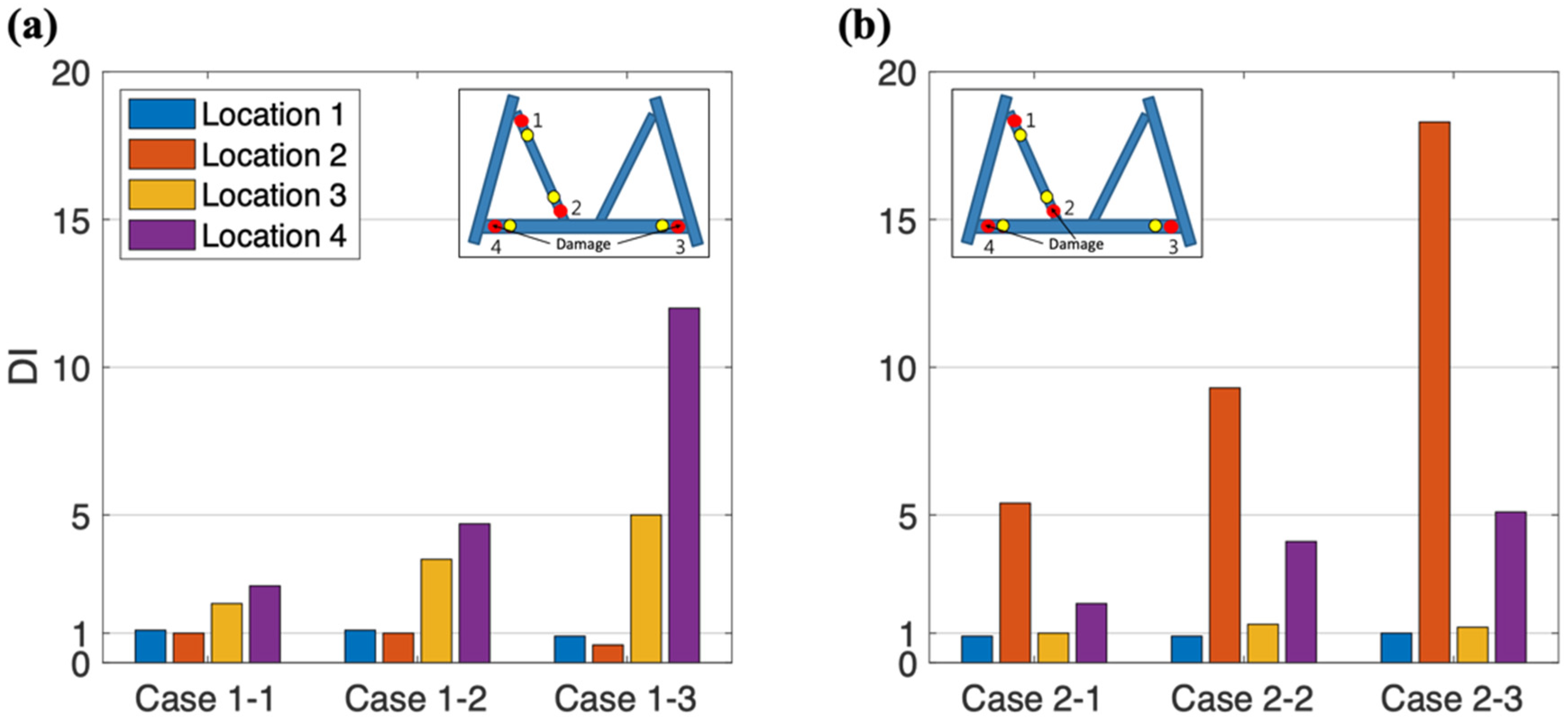
3.2. Identification of Multiple Instances of Damage for an OWT Substructure

We employed three cases (the calculated D I was determined by the data set recorded within eleven seconds) to investigate damage identification in multiple locations. In Case 1, damage occurred at Locations 3 and 4, which were on the same pipe. In Case 2, damage occurred at Locations 2 and 4, which were on different pipes. In Case 3, damage occurred in different pipes to differing degrees. The numerical results of Cases 1 and 2 and Case 3 are presented in Figure 5 and Figure 6, respectively.
The results in Figure 5 and Figure 6 were in excellent agreement with the conditions presented in Table 2. When the severity of the damage was increased (from Case 1-1 to Case 1-3), the D I at Locations 3 and 4 increased from 2 and 3.5 to 5 and 12 (Figure 5a), respectively. In Figure 5b, Case 2, representing multiple instances of damage in different pipes, also demonstrated the same trend as for Case 1. Furthermore, the D I values in locations with minor damage were at least 100% greater than the value in the undamaged section (Cases 1-1 and 2-1). Likewise, the D I values in locations with moderate and severe damage were at least 250% and 900% larger, respectively, than those in undamaged sections (Cases 1-2, 1-3, 2-2, and 2-3). The results indicated that the proposed approach can effectively identify damage severity in multiple damage sites irrespective of the pipe in which damage occurs. Two extremely high D I values (>10) were obtained in Cases 1-3 and 2-3 (the cause of extremely high values discussed in Section 3.1.3.); therefore, an extremely large D I could be only obtained in numerical calculations.
Regarding Case 3, Cases 3-1 and 3-2 represented different severities of damage in the same pipe, whereas Case 3-3 represented different severities of damage in different pipes. The D I values clearly identified severity in the two scenarios. Similar to those for Cases 1 and 2, the D I values in locations with minor and severe damage for Case 3 were at least two and ten times greater, respectively, than the value in the undamaged section. The results for Case 3 suggested that the approach could identify differing damage severity in different pipes. The results for all cases preliminarily confirmed the applicability of the method to an OWT jacket substructure.

3.3. Dominant Loading Analysis for Future Application of the SER Approach

To investigate dominant loading in the SER approach, we separated the total loading into the aerodynamic part (in the air) and the hydrodynamic part (underwater). The aerodynamic part was governed by the wind-loading–induced-bending moment to the tower bottom, where the moment was then transmitted to the substructure. By contrast, the hydrodynamic loading indicated that the wave loading directly acted on the structural member of the substructure (which was mainly out of plane). In Case 3-1, the D I values at Location 1 under wind loading and wave loading were 9.89 and 1.69, respectively.
Figure 7 presents a comparison of expanded strain and measured strain. The two strains in Figure 7a exhibited the same trend under wind loading; this was because the whole member was subjected to the same compression and tensile forces at the ends, which were caused by the bending moment from the tower. Due to reduced thickness at the damaged element, the measured strain was approximately twice the expanded strain, resulting in a higher D I value. However, the expanded strain under wave loading (Figure 7b) did not accord with the measurements. This was attributable to out-of-plane forces, such as wave slamming forces, that were applied inconsistently on the different locations of a member. The governing loading in this proposed method is, in short, the aerodynamic loading on the wind turbine. This finding suggests that the SER approach can be employed not only under normal operating conditions but also when the wind speed is sufficiently high. Moreover, the axial strain of a member under wind loading is greater than that under wave loading. Damage detection can be construed as being independent from wave loading. Therefore, for future applications, the measured D I can be set as a criterion to determine whether the member is damaged.

4. Conclusions

Numerical and experimental validation confirmed that the proposed SER approach is an effective method of damage identification. In the novel approach, the difference between the expanded and measured strains is used for damage identification. In the intact structure, the expanded strain is consistent with the measured strain. An increase in the severity of damage to the structure results in an increased difference between the expanded and measured strains. We defined D to quantify the difference in strain and determined D I to identify damage. A large value of D I indicated high severity of damage in the structure. For the structure with one slat possessing merely 0.5% damage zone, the calculated index is increased by 259% of the intact case. When the damage zone was doubled, the index increases significantly by 467% of the intact case. The difference of D I s between different DL1 and DL2 damage scenarios is up to 58% to determine the damage severity. By categorizing the D I levels, the severity of damage can be classified in future applications.
Moreover, numerical simulation confirmed that the novel damage identification method can be applied to an OWT jacket substructure to identify multiple damage sites in both the same pipe and different pipes. The D I values are extremely high (>10) for identifying the sites. Even if the severity at multiple damage sites is different, damages and their severity can still be discerned with distinct D I s . Thus, the proposed method is promising, can determine damage severity, and can provide information to enable a suitable solution to be found. The application of this method is expected to be extended to complicated situations. Besides, the results for the governing loading verified that our proposed method can be effectively employed not only under normal operating conditions but also when the wind speed is sufficiently high. By identifying the damage at an early stage, the method can reduce maintenance costs and even extend the service life of an OWT jacket substructure.

Author Contributions

Conceptualization, H.-H.H.; methodology, J.-H.H., D.-P.L. and H.-H.H.; software, J.-H.H. and D.-P.L.; validation, J.-H.H. and D.-P.L.; formal analysis, J.-H.H. and D.-P.L.; investigation, J.-H.H. and D.-P.L.; data curation, J.-H.H. and D.-P.L.; writing—original draft preparation, J.-H.H. and D.-P.L.; writing—review and editing, J.-H.H., D.-P.L. and H.-H.H.; visualization, J.-H.H. and D.-P.L.; supervision, C.-H.C. and H.-H.H.; funding acquisition, C.-H.C. and H.-H.H. All authors have read and agreed to the published version of the manuscript.

Funding

This work was funded by the Ministry of Science and Technology (MOST), Taiwan [grant No. 108-2628-E-002-007-MY3]; Bureau of Energy, Ministry of Economic Affairs (MOEA), Taiwan [grant No. 109-D0106]; and National Taiwan University, Taipei, Taiwan [grant Nos. NTU-CDP-109L7725].

Conflicts of Interest

The authors declare no conflict of interest.

References

  1. Farrar, C.R.; Worden, K. An introduction to structural health monitoring. Philos. Trans. R. Soc. A 2007, 365, 303–315. [Google Scholar] [CrossRef] [PubMed]
  2. Cawley, P.; Adams, R.D. The location of defects in structures from measurements of natural frequencies. J. Strain Anal. Eng. Design 1979, 14, 49–57. [Google Scholar] [CrossRef]
  3. Brownjohn, J.M. Structural health monitoring of civil infrastructure. Philos. Trans. R. Soc. A 2007, 365, 589–622. [Google Scholar] [CrossRef] [PubMed] [Green Version]
  4. Shokravi, H.; Shokravi, H.; Bakhary, N.; Heidarrezaei, M.; Rahimian Koloor, S.S.; Petrů, M. Application of the Subspace-Based Methods in Health Monitoring of Civil Structures: A Systematic Review and Meta-Analysis. Appl. Sci. 2020, 10, 3607. [Google Scholar] [CrossRef]
  5. Kong, X.; Cai, C.S.; Hu, J. The state-of-the-art on framework of vibration-based structural damage identification for decision making. Appl. Sci. 2017, 7, 497. [Google Scholar] [CrossRef] [Green Version]
  6. Dolinski, L.; Krawczuk, M. Analysis of Modal Parameters Using a Statistical Approach for Condition Monitoring of the Wind Turbine Blade. Appl. Sci. 2020, 10, 5878. [Google Scholar] [CrossRef]
  7. Eraky, A.; Anwar, A.M.; Saad, A.; Abdo, A. Damage detection of flexural structural systems using damage index method–Experimental approach. Alex. Eng. J. 2015, 54, 497–507. [Google Scholar] [CrossRef]
  8. Magalhães, F.; Cunha, A.; Caetano, E. Vibration based structural health monitoring of an arch bridge: From automated OMA to damage detection. Mech. Syst. Signal Process. 2012, 28, 212–228. [Google Scholar] [CrossRef]
  9. Chang, K.C.; Kim, C.W. Modal-parameter identification and vibration-based damage detection of a damaged steel truss bridge. Eng. Struct. 2016, 122, 156–173. [Google Scholar] [CrossRef]
  10. Devriendt, C.; Magalhães, F.; Weijtjens, W.; De Sitter, G.; Cunha, Á.; Guillaume, P. Structural health monitoring of offshore wind turbines using automated operational modal analysis. Struct. Health Monit. 2014, 13, 644–659. [Google Scholar] [CrossRef] [Green Version]
  11. Gauthier, J.F.; Whalen, T.M.; Liu, J. Experimental validation of the higher-order derivative discontinuity method for damage identification. Struct. Control Health Monit. 2008, 15, 143–161. [Google Scholar] [CrossRef]
  12. Weijtjens, W.; Verbelen, T.; De Sitter, G.; Devriendt, C. Foundation structural health monitoring of an offshore wind turbine—A full-scale case study. Struct. Health Monit. 2016, 15, 389–402. [Google Scholar] [CrossRef]
  13. Guyan, R.J. Reduction of stiffness and mass matrices. AIAA J. 1965, 3, 380. [Google Scholar] [CrossRef]
  14. Kidder, R.L. Reduction of structural frequency equations. AIAA J. 1973, 11, 892. [Google Scholar] [CrossRef]
  15. O’Callahan, J.C. System equivalent reduction expansion process. In Proceedings of the 7th International Modal Analysis Conference, Las Vegas, NV, USA, 30 January–2 February 1989. [Google Scholar]
  16. Kammer, D.C. A hybrid approach to test-analysis-model development for large space structures. J. Vib. Acoust. 1991, 113, 325–332. [Google Scholar] [CrossRef]
  17. Chipman, C.; Avitabile, P. Expansion of transient operating data. Mech. Syst. Signal Process. 2012, 31, 1–12. [Google Scholar] [CrossRef]
  18. Baqersad, J.; Poozesh, P.; Niezrecki, C.; Avitabile, P. A noncontacting approach for full-field strain monitoring of rotating structures. J. Vib. Acoust. 2016, 138, 031008. [Google Scholar] [CrossRef]
  19. Baqersad, J.; Bharadwaj, K. Strain expansion-reduction approach. Mech. Syst. Signal Process. 2018, 101, 156–167. [Google Scholar] [CrossRef]
  20. Yu, L.; Yin, T. Damage identification in frame structures based on FE model updating. J. Vib. Acoust. 2010, 132, 051007. [Google Scholar] [CrossRef]
  21. Betti, M.; Facchini, L.; Biagini, P. Damage detection on a three-storey steel frame using artificial neural networks and genetic algorithms. Meccanica 2015, 50, 875–886. [Google Scholar] [CrossRef]
  22. Han, D.; Wei, S.; Shi, P.; Zhang, Y.; Gao, K.; Tian, N. Damage identification of a Derrick steel structure based on the HHT marginal spectrum amplitude curvature difference. Shock. Vib. 2017, 2017, 1062949. [Google Scholar] [CrossRef] [Green Version]
  23. Guo, J.; Wu, J.; Guo, J.; Jiang, Z. A Damage Identification Approach for Offshore Jacket Platforms Using Partial Modal Results and Artificial Neural Networks. Appl. Sci. 2018, 8, 2173. [Google Scholar] [CrossRef] [Green Version]
  24. Rytter, A. Vibrational Based Inspection of Civil Engineering Structures. Ph.D. Thesis, Aalborg University, Aalborg, Denmark, 1993. [Google Scholar]
  25. Chian, C.Y.; Zhao, Y.Q.; Lin, T.Y.; Nelson, B.; Huang, H.H. Comparative study of time-domain fatigue assessments for an offshore wind turbine jacket substructure by using conventional grid-based and monte carlo sampling methods. Energies 2018, 11, 3112. [Google Scholar] [CrossRef] [Green Version]
  26. Chen, I.W.; Wong, B.L.; Lin, Y.H.; Chau, S.W.; Huang, H.H. Design and analysis of jacket substructures for offshore wind turbines. Energies 2016, 9, 264. [Google Scholar] [CrossRef] [Green Version]
Figure 1. Schematic of the damage identification approach; “e” and “m” denote expanded and measured strains, respectively.
Applsci 10 07991 g001
Figure 2. (a) Schematic of acrylic frame; (b) damage scenarios.
Applsci 10 07991 g002
Figure 3. Jacket support structure numerical model (yellow and red points are measured and expanded points, respectively).
Applsci 10 07991 g003
Figure 4. Numerical results of (a) INT (intact), (b) DL1 (mildly damaged), and (c) DL2 (severely damaged); experimental results of (d) INT, (e) DL1, and (f) DL2; “e” and “m” denote expanded and measured strains.
Applsci 10 07991 g004
Figure 5. Same damage in multiple locations for (a) Case 1 (damage in the same pipe) and (b) Case 2 (damage in different pipes).
Applsci 10 07991 g005
Figure 6. Damage of differing severity in multiple locations.
Applsci 10 07991 g006
Figure 7. Simulation results of Case 3-1 at Location 1 under (a) wind loading and (b) wave loading; e and m denote expanded and measured strains, respectively. We eliminated the first 5 s of simulation results, which were calculated as the preloading step.
Applsci 10 07991 g007
Table 1. Pipe damage scenarios.
ScenarioDescription
INTIntact pipe, 18.9 mm thickness
DL1Minor damage, 79.4% thickness
DL2Moderate damage, 63.5% thickness
DL3Severe damage, 52.9% thickness
Table 2. Damage severity at different locations on the pipe.
Location 1Location 2Location 3Location 4
Case 1-1IntactIntactMinor damageMinor damage
Case 1-2IntactIntactModerate damageModerate damage
Case 1-3IntactIntactSevere damageSevere damage
Case 2-1IntactMinor damageIntactMinor damage
Case 2-2IntactModerate damageIntactModerate damage
Case 2-3IntactSevere damageIntactSevere damage
Case 3-1Severe damageMinor damageIntactIntact
Case 3-2IntactIntactMinor damageSevere damage
Case 3-3IntactSevere damageIntactMinor damage
Publisher’s Note: MDPI stays neutral with regard to jurisdictional claims in published maps and institutional affiliations.

