Abstract
In this paper, a novel photonic scheme for the generation of square and triangular waveforms is proposed and experimentally demonstrated by using a dual-drive Mach–Zehnder modulator (DDMZM) without any optical signal processing. By properly setting the modulation index of the DDMZM, the square and triangular microwave waveforms could be easily achieved in conjunction with a 90° hybrid coupler. Furthermore, the modulation index of the DDMZM could be tuned for a low radio frequency (RF) signal power requirement by tuning the phase difference of the RF signals applied to the two arms of the DDMZM. The proposed scheme for the photonic generation of microwave waveforms is theoretically analyzed and experimentally demonstrated. The periodical triangular and square waveforms with repetition rates of 5 GHz, 8 GHz, and 10 GHz are successfully obtained. The root-mean-square errors between the generated and theoretical triangular and square waveforms with a repetition of 5 GHz are 0.042 and 0.053, respectively.
1. Introduction
The photonic generation of a microwave waveform signal has become a quite attractive research area in recent years. The generation of square and triangular pulses has aroused widespread concern, as they are widely used in modern electronic systems such as wireless communication systems [1,2], all-optical signal processing systems [3,4], radars [5], and sensors [6]. Until now, various photonic square and triangular signal generation schemes have been proposed [7,8,9,10,11,12]. Among them, the external modulation of a continuous wave (CW) is an efficient and promising solution to generate microwave waveforms with a full duty cycle.
The basic principle is to generate the desired harmonics corresponding to the Fourier series expansion components of the desired pulse train in the frequency domain. For example, in paper [13], a Mach–Zehnder modulator (MZM) and a span of dispersion fiber were used to generate triangular pulses. In this scheme, the dispersive fiber was used to form a microwave photonic filter with a periodic response, so as to suppress the undesired even-order harmonics. In paper [14], a scheme for the generation of triangular pulse using a MZM was proposed. Additionally, an optical interleaver (IL) combined with a tunable optical delay line (ODL) was used to introduce a time delay between the first and third optical sidebands. However, the repetition rate was limited by the optical signal processing components in such schemes, such as dispersion compensation fibers (DCFs), ODLs, or ILs. The triangular signal generation could also be achieved by employing stimulated Brillouin scattering (SBS) effects in optical fiber [15,16]. In paper [17], triangular and square waveforms were obtained with the assistance of a Sagnac loop and two single-drive MZMs. A more simplified scheme was realized by adjusting the DC bias voltage and modulation coefficient of a dual-parallel Mach–Zehnder modulator (DPMZM) appropriately [18,19]. Furthermore, no optical filtering device was required in such schemes. However, two sub-modulators of DPMZM must have been driven by two different RF signals. Additionally, the accurate DC bias control was limiting the practicality of the system. In paper [20], a MZM and a hybrid coupler were employed to generate triangular and square waveforms. In this scheme, the MZM, a push-pull intensity modulator, which meant the input RF signals loaded on the two arms had a π phase difference, was operated at the quadrature bias point to effectively suppress the even-order harmonics at a high input power. In paper [21], Jin Yuan proposed a novel scheme to generate a triangular-shaped waveform based on two cascaded DDMZMs, no electric filter or phase shifter was used in the system, while a Fiber Bragg Grating (FBG) was necessary after the DDMZMs.
In this paper, we propose and experimentally demonstrate a simple photonic method for the simultaneous generation of square and triangular waveforms without any filtering or dispersive elements with a low RF signal power requirement. This scheme only requires a sinusoidal RF source, a DDMZM, a RF power splitter in conjunction with a phase shifter, a photodetector (PD), and a 90° hybrid coupler. By simply adjusting the input power of the RF signal applied to the power splitter appropriately, the first- and third-order harmonic signals of the photocurrent compose a spectrum of a desired pulse train. A hybrid coupler is utilized after the photodetector made the phase of the first- and third-order harmonics conform to the required relation. The signal generation is realized by using the characteristics of DDMZM to control the phase and amplitude of the optical sidebands. This scheme can greatly simplify the configuration of the system. The principle of the scheme is theoretically analyzed and experimentally verified. The generation of square and triangular waveforms is demonstrated. Furthermore, the pulse trains with repetition rates of 5, 8, and 10 GHz are successfully achieved, which guarantees the feasibility of the scheme.
2. Operation Principle
Figure 1 shows the configuration of the proposed waveform generation scheme. In the proposed scheme, an optical carrier generated from a continuous wave (CW) laser was coupled into an commercial off-the-shelf DDMZM, which had two RF input ports and two independent DC biases. The sinusoidal RF signal was split into two channels by an RF power splitter, with one output port connected to the upper arm of the DDMZM and the other output port connected to the lower arm of the DDMZM via a phase shifter. The optical signal was modulated by the RF signal via the DDMZM to generate optical sidebands. Assuming the optical field of the carrier is expressed as Ein(t) = Ein exp(jω0t) and Vπ is the half-wave voltage of the DDMZM, the output optical fields of the upper and the lower arm are:
where VRF and ωRF are the amplitude and frequency of the RF signal, and θ is the phase difference of the RF signals applied to the two arms. VDC1 and VDC2 denote the two bias voltages applied to the upper and lower arms, respectively. Then, the optical field at output of DDMZM can be expressed as:
where and are phase shift determined by the bias voltages, represents the phase difference caused by the two bias voltages, and is the modulation index of the DDMZM. When this optical signal was sent to a PD for intensity detection, the output current of the PD was given by:
where is the responsivity of the PD. It can be perceived from Equation (3) that the desired waveforms can be obtained by properly setting the coefficients of β and θ.
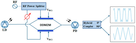
Figure 1.
Schematic diagram of the proposed full-duty-cycle square and triangular pulses generator based on a DDMZM. LD: Laser diode; DDMZM: Dual-drive Mach–Zehnder Modulator; PD: Photodetector; OSC: Oscilloscope; ESA: Electrical spectrum analyzer.
2.1. Square waveform
As we all know, the Fourier expansion of the square waveform can be expressed as:
If we set , and neglect the higher order harmonics, which means the DDMZM working at the quadrature point and the input signal of its two arms have a phase difference of θ, and considering:
then, Equation (3) can be simplified as:
where J2m−1 denotes the (2m − 1)th order of the first kind of Bessel function. Here, is defined as the coefficient ratio of the fundamental and third harmonic signals. As can be seen from Equation (6), only odd order harmonics exist, and even order harmonics are effectively suppressed. Comparing Equation (4) with Equation (6), the relationship between frequency and phase satisfies the requirement for square waveform generation. On the condition that r1/3 is approximately 3:1, the output photocurrent may present a square waveform in the time domain. In the proposed approach, the desired ratio r1/3 is 3 for the generation of the square waveform which will be achieved for setting the appropriate β with different θ. Figure 2 gives the relationship between the modulation index β and the coefficient ratio of the fundamental and third harmonic signals r1/3 with different θ. As can be seen from Figure 2, the optimized operation for r1/3 = 3 will be easily realized when β is set to be 2.29 rad, 1.6 rad, and 1.15 rad by properly setting the input RF power at the θ of π/3, π/2 and π, respectively. Since the square waveform generation needs no phase shift, it can be obtained at the 0° output port of the 90° hybrid coupler.
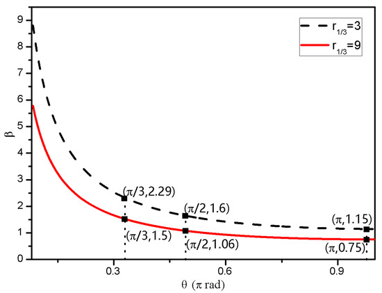
Figure 2.
The calculated modulation index β versus the phase difference θ.
2.2. Triangular waveform
In principle, the Fourier expansion of triangular waveform can be expressed as:
Comparing Equation (6) with Equation (7), Equation (6) contains all the required odd order harmonics, when we set , and neglect the higher order harmonics, which means the DDMZM working at the quadrature point and the input signal of its two arms have a phase difference of θ. The triangular waveform can be obtained under the condition that the ratio of the fundamental and third harmonic signals r1/3 is approximately 9:1. According to Figure 2, the optimized operation for r1/3 = 9 will be easily realized when β is set to be 1.5, 1.06, and 0.75 by properly setting the input RF power at the θ of π/3 rad, π/2 rad, and π rad, respectively. Besides, a 90° hybrid coupler is attached after the PD to compensate for the phase mismatch. The ultimate output electric current Equation (6) can then be further expressed as:
As can be seen from Equation (8), a theoretical full-duty triangular pulse train is successfully obtained.
The proposed scheme is quite simple in structure and easy to implement. Since no further filtering or dispersing elements were needed in the scheme, the frequency of the generated pulse train could be tuned by simply tuning the input RF signal frequency.
3. Experiment and Results
The schematic setup based on Figure 1 was experimentally performed to verify the effectiveness of the proposed approach for the generation of square and triangular waveforms. The optical signal from the TLS (NKT, E15) with the wavelength of 1549.955 nm, and the power of 8 dBm was sent to the DDMZM (EOSPACE, 40 GHz). The modulator had a half-wave voltage of 4.4 V. Furthermore, it was biased at the quadrature point. To simplify the experimental operation, a 180° hybrid coupler was used instead of a RF coupler and a phase shifter, on the condition that θ = π. A 5 GHz RF signal generated from the single frequency source (Agilent E4438C) was divided by the 180° hybrid coupler and then applied to the two arms of the modulator. Afterwards, the modulated optical signal was sent to the PD (Finisar, 50 GHz) for intensity detection. The responsivity of the PD was about 0.6 A/W. Additionally, the 3 dB bandwidth was 50 GHz. An electrical amplifier with a gain of 30 dB was employed after the PD to boost the generated pulse train signal. In order to fit the phase condition for the first and third order harmonics, a 90° hybrid coupler was applied afterward. In the end, the electric signal was divided by a power splitter. One part was sent to the electrical spectrum analyzer (ESA, Agilent, E4440A), and the other to the oscilloscope (OSC, Keysight, UXR0704AP).
For the generation of the square waveform, the DDMZM was first driven by a 5 GHz RF signal. Adjusting the input RF power to make sure that the modulation index β = 1.15, we got a square waveform from the 0° port of the hybrid coupler. The electric spectrum is shown in Figure 3a. The even-order harmonics were completely suppressed. The third-order harmonics at 15 GHz was 9.62 dB lower than the fundamental harmonic, which was very close to the theoretical calculation result. Figure 3b shows the generated square waveform compared with the theoretical waveform. The measured square waveform fit well with the theoretical waveform. The root-mean-square error (RMSE) between the measured and theoretical waveform was calculated as 0.053.
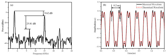
Figure 3.
Measured (a) electrical power spectrum and (b) waveforms of the generated square waveform with a repetition rate of 5 GHz.
By adjusting the input RF power, the triangular waveform could be obtained from the 90° port of the hybrid coupler. Figure 4 shows the electrical power spectrum and waveform of the generated triangular pulse train. As can be seen from Figure 4a, the even-order harmonics are completely suppressed and the power of the third-order harmonic is 18.8 dB lower than that of the fundamental frequency. This power is very close to the theoretical value (19.08 dB lower than the fundamental frequency). As given by Figure 4b, a full-duty-cycle triangular train with a time period of 0.2 ns is obtained. The RMSE is 0.042 for the triangular waveforms with a repetition rate of 5 GHz.
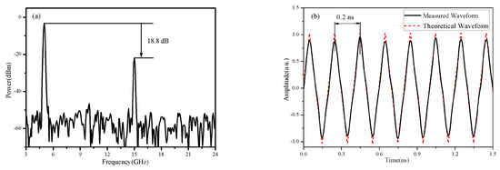
Figure 4.
Measured (a) electrical power spectrum and (b) waveforms of the generated triangular pulse trains with a repetition rate of 5 GHz.
In order to verify the tunability of the system, the frequency of the signal source was set to 8 GHz and 10 GHz, respectively. The corresponding electrical spectrum and time-domain triangular wave signal were also obtained, as shown in Figure 5 and Figure 6. It can be seen from Figure 5a,c and Figure 6a,c that the even-order harmonics are well suppressed. For both the 8 GHz and 10 GHz signals, the second harmonic is around 36 dB below the fundamental term. The corresponding square waveforms with the period of 0.125 ns and 0.1 ns are observed in Figure 5b,d. This is in good agreement with the theoretical waveform. It should also be pointed out that the frequency response of the DDMZM is not perfect and fluctuates within the operating bandwidth. Hence, the RF signal power should be adjusted accordingly as the frequency increases.
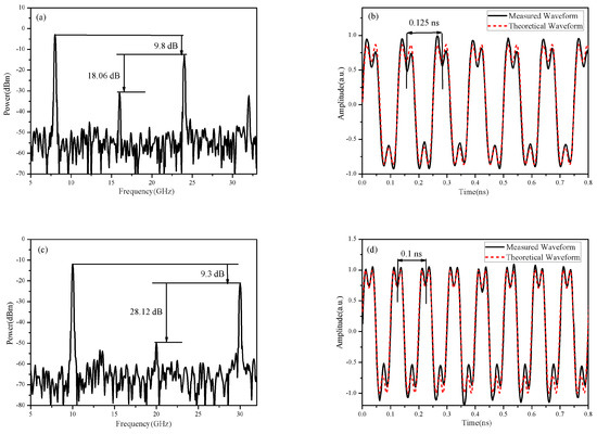
Figure 5.
Electrical power spectrum and waveforms of the generated square waveform with repetition rates of 8 GHz (a) and (b), 10 GHz (c) and (d).
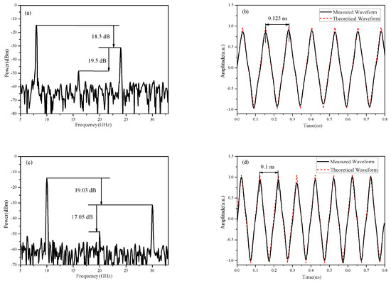
Figure 6.
Electrical signal spectrum and waveforms of the generated triangular pulse trains with repetition rates of 8 GHz (a) and (b), 10 GHz (c) and (d).
Finally, in view of the fact that this scheme is not sensitive to the phase difference of the RF signals of the two arms, we have also realized the generation of the square and triangular waveforms experimentally when we adjusted the phase shifter, making the phase of the 5 GHz signal for 60°, 90°, and 180°, respectively. The applied RF signal power also needed to be adjusted accordingly to achieve a certain modulation depth. When making the phase for 180° by tuning the phase shifter, the required RF signal power was the smallest and the system efficiency was the highest. As shown in Figure 7, when the phase changes from 180° to 90°, the RF power arises from 14.46 dBm to 17.43 dBm. When the phase was changed to 60°, the input power increased to 20.51 dBm. This is very consistent with the theoretical calculation, as shown in Figure 2. The RMSEs between the generated waveforms and the theoretical waveform are 0.053, 0.050, and 0.058, respectively.
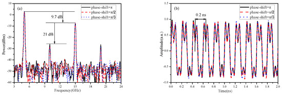
Figure 7.
The generated square waveform with a repetition rate of 5 GHz for different phases. (a) The spectrum and (b) waveforms of the generated signals.
4. Conclusions
To sum up, we proposed and experimentally demonstrated a simple scheme for the generation of full-duty-cycle square and triangular pulse trains using a DDMZM. No additional assistant optical spectral processing was needed in our scheme. Full-duty-cycle square and triangular pulse trains with repetition rates of 5, 8, and 10 GHz were successfully generated. The RMSEs between the generated triangular waveform and the theoretical waveform with repetition rates of 5 GHz, 8 GHz, and 10 GHz are 0.042, 0.046, and 0.078, respectively. The degradation of RMSE may be due to the phase error between the first- and third-order harmonics which originate from the electrical amplifier connected to the PD and the hybrid coupler. This scheme has good practicality in engineering with the utilization of a bias controller.
Author Contributions
J.L. designed and set up the experiment; Z.R. and J.Z. carried out the measurements under the supervision of J.H., M.Z. and Y.G. provided the theoretical support for modelling the experiment. J.L. wrote the manuscript and all authors suggested improvements. All authors have read and agreed to the published version of the manuscript.
Funding
This work was supported in part by National Key Research and Development Project (2019YFB2203201), National Natural Science Foundation of China (61605023, 61805032, 61875028, 61520106013, and 61727816), National Research Foundation of China (6140450010305 and 61404130403), Dalian Science and Technology Innovation Foundation (2018J11CY006), and Fundamental Research Funds for the Central Universities.
Conflicts of Interest
The authors declare no conflict of interest.
References
- Parmigiani, F.; Ibsen, M.; Petropoulos, P. Efficient All-Optical Wavelength-Conversion Scheme Based on a Saw-Tooth Pulse Shaper. IEEE Photonics Technol. Lett. 2009, 21, 1837–1839. [Google Scholar] [CrossRef]
- Jeongwoo, H.; Nguyen, C. A new ultra-wideband, ultra-short monocycle pulse generator with reduced ringing. IEEE Microw. Wirel. Compon. Lett. 2002, 12, 206–208. [Google Scholar] [CrossRef]
- Yuan, J.; Ning, T.; Li, J. Investigation on optical wavelength conversion based on SPM using triangular-shaped pulses. Opt. Int. J. Light Electron Opt. 2015, 127, 3049–3054. [Google Scholar] [CrossRef]
- Latkin, A.-I.; Boscolo, S.; Bhamber, R.-S. Doubling of optical signals using triangular pulses. J. Opt. Soc. Amer. B. 2009, 26, 1492–1496. [Google Scholar] [CrossRef]
- Won, Y.-S.; Kim, C.-H.; LEE, S.-G. Range resolution improvement of a 24 GHz ISM band pulse radar—A feasibility study. IEEE Sens. J. 2015, 15, 7142–7149. [Google Scholar] [CrossRef]
- Wang, X.-W.; Li, Y.-F.; Zhou, Y. Triangular-range-intensity profile spatial-correlation method for 3D super-resolution range-gated imaging. Appl. Opt. 2013, 52, 7399–7406. [Google Scholar]
- Zhou, P.; Zhang, F.; Guo, Q. A Modulator-Free Photonic Triangular Pulse Generator Based on Semiconductor Lasers. IEEE Photonics Technol. Lett. 2018, 30, 1317–1320. [Google Scholar] [CrossRef]
- He, Y.-T.; Jiang, Y.; Zi, Y.-J. Photonic microwave waveforms generation based on two cascaded single-drive Mach-Zehnder modulators. Opt. Express 2018, 26, 7829–7841. [Google Scholar] [CrossRef] [PubMed]
- Yuan, J.; Ning, T.; Li, J. Research on photonic generation of quadrupling triangular-shaped waveform using external modulation. Opt. Fiber Technol. 2018, 45, 352–358. [Google Scholar] [CrossRef]
- Zeng, Z.; Zhang, L. Frequency-definable linearly chirped microwave waveform generation by a Fourier domain mode locking optoelectronic oscillator based on stimulated Brillouin scattering. Opt. Express 2020, 28, 13861–13870. [Google Scholar] [CrossRef]
- Song, C.; Qian, J.; Lei, M. A Chirp-Rate-Tunable Microwave Photonic Pulse Compression System for Multi-Octave Linearly Chirped Microwave Waveform. IEEE Photonics J. 2019, 11, 1–13. [Google Scholar] [CrossRef]
- Zhang, L.; Zeng, Z.; Zhang, Y. Photonics-assisted bandwidth-doubling dual-chirp microwave signal generation with freely-tunable central frequency. IEEE Photonics J. 2020, 12, 1–11. [Google Scholar] [CrossRef]
- Li, W.; Wang, W.; Sun, W. Generation of triangular waveforms based on a microwave photonic filter with negative coefficient. Opt. Express 2014, 22, 14993–15001. [Google Scholar] [CrossRef] [PubMed]
- Li, J. Photonic-assisted periodic triangular-shaped pulses generation with tunable repetition rate. IEEE Photon. Technol. Lett. 2013, 25, 952–954. [Google Scholar] [CrossRef]
- Sun, W.-H.; Li, W.; Wang, W.-T. Triangular Microwave Waveform Generation Based on Stimulated Brillouin Scattering. IEEE Photonics J. 2014, 6, 1–7. [Google Scholar] [CrossRef]
- Liu, X. Photonic generation of triangular-shaped microwave pulses using SBS-based optical carrier processing. J. Light W. Technol. 2014, 32, 3797–3802. [Google Scholar] [CrossRef]
- Zhai, W.-L.; Wen, A.-J. Photonic Generation and Transmission of Frequency-Doubled Triangular and Square Waveforms Based on Two Mach–Zehnder Modulators and a Sagnac Loop. J. Lightwave Technol. 2019, 37, 1937–1945. [Google Scholar] [CrossRef]
- Li, J. Photonic generation of triangular waveform signals by using dual-parallel Mach–Zehnder modulator. Opt. Lett. 2011, 36, 3828–3830. [Google Scholar] [CrossRef] [PubMed]
- Zhang, F.; Ge, X.; Pan, S.-L. Triangular pulse generation using a dual-parallel Mach–Zehnder modulator driven by a single-frequency radio frequency signal. Opt. Lett. 2013, 38, 4491–4493. [Google Scholar] [CrossRef]
- Sha, Z.; Xin, W. A simple photonic method to generate square and triangular microwave waveforms. Opt. Commun. 2018, 426, 654–657. [Google Scholar]
- Yuan, J.; Ning, T.; Li, J. Photonic Generation of Triangular-shaped Waveform Based on External Modulation. Sci. Rep. 2018, 8, 3369. [Google Scholar] [CrossRef]


Publisher’s Note: MDPI stays neutral with regard to jurisdictional claims in published maps and institutional affiliations. |
© 2020 by the authors. Licensee MDPI, Basel, Switzerland. This article is an open access article distributed under the terms and conditions of the Creative Commons Attribution (CC BY) license (http://creativecommons.org/licenses/by/4.0/).