Abstract
This paper investigated the diffraction of a Gaussian laser beam on a binary mask and a refractive axicon. The principles of the formation of a zero-order Bessel beam with sharp drops of the axial field intensity edges were discussed. A laser optical system based on an axicon for the formation of a Bessel beam with quasi-uniform distribution of axial field intensity was proposed. In the laser optical system, the influence of the axicon apex did not affect the output beam. The results of theoretical and experimental studies are presented. It is expected that the research results will have practical application in optical tweezers, imaging systems, as well as laser technologies using high-power radiation.
1. Introduction
Research on the methods of focusing light beams associated with the names of such scientists as Ernst Abbe, George Airy, and John Strutt have a long history and remain relevant to this day. Tight focusing of laser radiation, which allows one to obtain high power densities and directivity, is in demand in many problems of photonics and laser physics [1,2,3,4,5,6].
In practice, Gaussian laser beams are widely used. When they are focused using an optical system with spherical (or parabolic) surfaces, it is possible to concentrate laser radiation in the region corresponding to the beam waist diameter. However, in Gaussian beams, the wavefront is flat only in the waist region, the length of which is equal to the confocal parameter. With a decrease in the waist diameter of a Gaussian beam, its confocal parameter decreases [7,8,9].
By choosing the type and shape of the surfaces of the laser optical system elements, it is possible to correct the geometry of the wavefront. Correction methods can also be applied to increase the focusing length of the formed beam. In the end, when the lens takes the form of a cone, the phase front of the transmitted wave becomes conical. Such a conical lens is called an axicon [10]. The axicon forms a beam with a radial distribution of field intensity, which is described by the Bessel function of the first kind of the zero-order. Such beams are often used for scientific and applied problems [11,12], in which they have advantages over Gaussian beams [13,14]. The main ones are: (i) the transverse distribution of field intensity remains practically unchanged over a significant portion along the optical axis, (ii) the distribution of the field is restored behind obstacles, and (iii) excellent depth of field.
Axicon is a reliable optical element for the formation of a zero-order Bessel beam, including schemes with high-power laser radiation. However, it has disadvantages such as the dependence of the parameters of the generated beam on a specific element, the dependence of the intensity distribution of the output beam on the quality of element manufacturing (in particular, on the quality of the apex), and uneven distribution of axial intensity [15].
There is a huge number of different tools used for the formation of Bessel beams [16,17] which allow controlling axial intensity distribution. Diffraction [18,19] and holographic methods [20] are outside of the scope of this study due to the features of their implementation. Methods capable of realizing the required Bessel beam intensity profiles are widely used in microscopy [21], including biological imaging [22,23,24], as well as in applications of ultrashort laser pulses [25,26]. In almost all of the abovementioned applications, a Bessel beam with a controlled quasi-uniform axial intensity distribution is formed.
The only way to change the axial intensity is to apodize the beam incident on the element (axicon or lens). In research, phase masks with a gradient, step, or both dependences of the phase shift value on the radius vector in combination with an axicon or a lens are actively used [27,28]. There are also sophisticated ways to achieve the same goal [29].
Research in the field of parametrization of the quasi-uniform axial intensity distribution of the Bessel beam is relevant. The purpose of this work was to develop a laser optical system for forming a Bessel beam with a controlled quasi-uniform axial distribution of field intensity on a standard element base with a minimum number of optical elements without significant restrictions on their radiation resistance. Research is being carried out on the possibility of realizing such a laser optical system by apodizing the input aperture of the axicon.
2. Modeling
The fundamental TEM00 mode formed by laser resonators of a stable configuration corresponds to a Gaussian beam with a radially symmetric field distribution [30]:
where is the distribution of the complex amplitude of the Gaussian beam in the section with the coordinate from the waist; denotes the distance from the observation point in the beam to the axis; are the transverse coordinates; denotes the amplitude constant or the field amplitude on the axis () in the section of the beam waist (); and are the dependences of the caustic and radius of wavefront curvature of the beam in section ; denotes the waist diameter of the Gaussian beam; is Rayleigh length of the Gaussian beam; is laser wavelength; is the parameter quality of a Gaussian beam.
Let us consider the transformation of a Gaussian beam with field distribution Equation (1) by a binary mask and a refractive axicon with a refractive index and apex angle (Figure 1). In wave optics, the effect of an axicon is described by the complex amplitude transmittance [31]: , where is amplitude transmittance, is phase transmittance, is the numerical aperture of the axicon, is the angle of wavefront inclination to the optical axis after passing through the axicon in the case of the plane homogeneous wave.
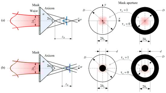
Figure 1.
Schemes for the formation of a zero-order Bessel beam with a quasi-rectangular dependence of axial intensity: (a) the Bessel zone starts right after the axicon; (b) the Bessel zone is moved away from the axicon. —waist diameter of the Gaussian beam, —apex angle axicon, —refractive index axicon, —analysis plane after the axicon, —length of the Bessel zone, D—clear aperture of the binary mask, d—diameter of the inner aperture of the mask, —amplitude transmittance.
If the effect of the axicon has only a phase nature, then the generated Bessel beam of the zero-order is characterized by the length of the Bessel zone and the diameter of the core (diameter of the central maximum) of the field intensity distribution of the Bessel beam. They are defined by the following expressions [32,33]:
Such a Bessel beam also has an uneven distribution of axial field intensity [33,34]:
where is the analysis plane after the axicon and denotes the power of laser radiation.
Let us investigate the influence of binary mask parameters and the input Gaussian beam on forming a quasi-rectangular axial intensity distribution of the zero-order Bessel beam. Amplitude transmittance is determined by the finite axicon aperture and the nature of its transmission within the clear aperture. The calculation of the transverse distribution of field intensity in the analysis plane after the axicon is performed using a certain transfer operator. The choice of the transfer operator depends on the distance between the original plane and the analysis plane. The nonparaxial scalar model based on Rayleigh–Sommerfeld theory allows to obtain correct results at sufficiently close distances from the aperture of the optical element at which the diffraction occurs. Using the integral Rayleigh–Sommerfeld transform of the first type, we find the amplitude-phase distribution of the beam field in the plane of analysis after the axicon [34,35]:
where is distribution of the complex field amplitude before the axicon, denotes oblique length equal to the distance between the point at which the initial distribution of the complex amplitude of the field is specified and a point in the analysis plane after the axicon. To calculate the axial intensity of the output field, we use the following expression for : .
When calculating amplitude-phase field distributions using the integral Rayleigh–Sommerfeld transform within the nonparaxial scalar model, it is necessary to consider the efficiency and error of numerical methods when working with rapidly oscillating functions. One of such practical methods is Levin’s method [36], which allows one to calculate integrals with complex integrands of strongly oscillating functions. According to Levin’s method, the one-dimensional oscillating integral is transformed into an ordinary differential equation which can then be solved by the collocation method [37].
The parameters of the axicon directly determine the distribution of the beam field in the analysis plane after the axicon, but do not affect the general nature of the effect under study. The presence of a binary mask in front of the axicon leads to the fact that the longitudinal dependence of axial intensity of the Bessel beam does not obey Equation (3). The distribution of the axial intensity of the Bessel zone is modified in such a way that the width of the central core and concentric rings remains unchanged in a certain interval, while the length of the Bessel zone decreases. With different parameters of the binary mask transmission function, it is possible to achieve a sharp change in the edge of the axial intensity distribution of the Bessel zone (Figure 2a–d).
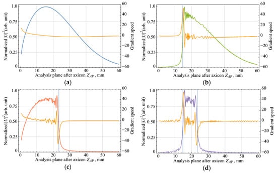
Figure 2.
Axial intensity distributions of a Bessel beam and the gradient from the longitudinal coordinate for various parameters of the mask before the axicon: (a) without binary mask, mm, ; (b) with binary mask, mm, ; (c) with binary mask, mm; (d) with binary mask, mm.
The analysis of the axial intensity distributions of the Bessel zone was carried out using the gradient of the scalar function, which shows the direction and rate of its most rapid increase/decrease [38,39]. In Figure 2, orange plots represent the value of the function gradient for each point in the analysis plane after the axicon. Based on the data, it follows that there was an abrupt change in the speed and direction of the gradient of the function.
The position of the beam focusing plane after the axicon can be calculated using Equation (2) for the length of the Bessel zone , in which the input beam waist is substituted for beam height. The results of this calculation are also compared in Figure 2, where the dotted vertical lines show the positions of the focusing plane according to the ray model. The calculations based on the wave theory correlate well with the ray model. It is important to note that the length and position of the Bessel zone directly depend on the parameters of the amplitude mask: the left boundary along the propagation direction is determined by the size of the inner aperture of the mask, and the right boundary is determined by the outer aperture of the mask. The effective length of the Bessel zone is defined as the difference between the positions corresponding to the outer and inner boundaries of the amplitude mask.
3. Experimental Implementation of the Bessel-Gaussian Beam
3.1. Experimental Setup
The possibility of implementing the previously proposed method has been confirmed experimentally. The source was a diode-pumped CW single-frequency laser (Cobolt AB, Solna, Sweden) with a wavelength of nm, which also had a spatial single-mode transverse field structure () with a quality factor . An afocal optical system was used to expand the laser beam to a diameter of 4 mm (at width). Then, a quasi-parallel laser beam illuminated the mask and the axicon. The axicon AX2510-A (Thorlabs, Newton, NJ, USA) had the following parameters: aperture diameter 25.4 mm, apex angle . The mask (BMSTU, Moscow, Russia) was installed directly, close to the front surface of the axicon. The mask we used was glass plane-parallel plates with a circular aperture 25.4 mm in diameter, on one of the surfaces of which a sufficiently thick layer of chromium () was applied. Figure 1 shows the masks used in the research. The parameters of the mask (clear and inner apertures) were designed the same as in modeling and mentioned in the caption of Figure 2. To register the axial intensity distribution after the axicon, an afocal optical system with 3x magnification was placed in front of a sCMOS camera CS2100M-USB (Thorlabs, Newton, NJ, USA) on the optical axis.
3.2. Results and Analysis
The axial field intensity distributions were acquired with a step of 1 mm along the optical axis. The effect of a diaphragmed Gaussian beam on the axial intensity and length of the Bessel zone is shown in Figure 3a–d. The dots denote the experimental data, and the solid line denotes the approximated experimental data. It can be seen that the experimental results are in good agreement with the theoretical calculations presented in Section 2.
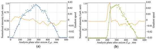
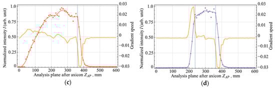
Figure 3.
Axial intensity distributions of a zero-order Bessel beam and gradient from the longitudinal coordinate for various parameters of the binary mask in front of the axicon: (a) without binary mask, mm, ; (b) with binary mask, mm, ; (c) with binary mask, mm; (d) with binary mask, mm.
For the sections corresponding to the region of abrupt change in axial field intensity (vertical dashed lines in Figure 3a–d), the cross-sections of field intensity are shown in Figure 4. The results of calculating the gradient of the function are presented in yellow lines in Figure 3. The most interesting area from the entire dependence of the axial intensity distribution of the Bessel zone was the leading and trailing edges. When a Gaussian beam hit an axicon without a mask, the gradient of the function had equal rise and fall times, Figure 3a. In the case when the outer or inner part of the Gaussian beam was diaphragmed, only one edge of the Bessel beam field intensity changed, as described in Section 2. With the external diaphragm, the leading edge in the function remained unchanged, and with the internal diaphragm, the trailing edge remained unchanged. In this case, the rate of change of the intensity distribution profile in the studied areas increased by more than 4 times. In Figure 3b,c, one can see these jumps in the gradient speed. After installing the mask with annular aperture, two sharp changes in axial intensity were obtained, Figure 3d. The rate of change also increased by more than 4 times.
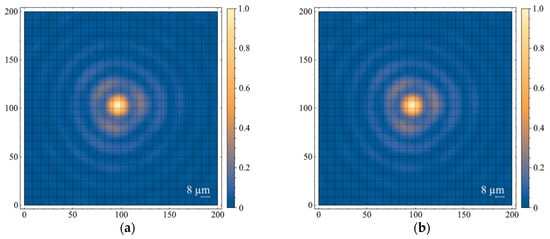
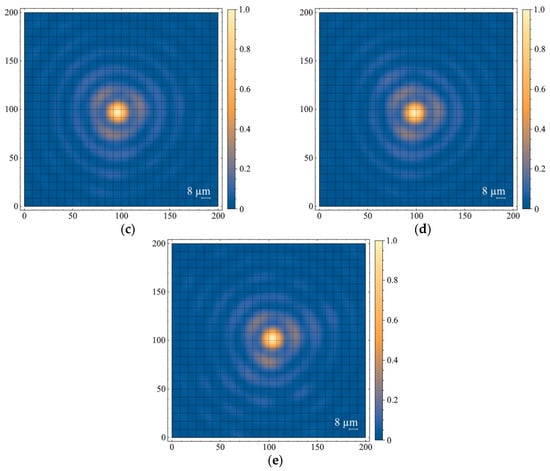
Figure 4.
Cross sections of field intensity: (a) without binary mask, mm, ; (b) with binary mask, mm, , Zap = 240 mm; (c) with binary mask, mm, Zap = 360 mm; (d) with binary mask, mm, Zap = 240 mm; (e) with binary mask, mm, Zap = 360 mm.
As mentioned earlier, Figure 4 shows the cross sections of the field intensity distribution of the Bessel beam. As a reference distribution, we took the cross section that corresponded to Figure 4a, when a Gaussian beam with a diameter of 4 mm without apodization fell on the axicon. It can be seen that there were features of the zero-order Bessel function in each distribution that are of interest. The absolute value of field intensity in the analysis plane for the cases in Figure 4b–e corresponds to the intensity profile shown in Figure 3a. Apodization of the beam incident on the axicon did not in any way affect the size or shape of the central maximum (the nucleus of the Bessel zone).
The change in relative position of the Bessel zone core in Figure 4 was associated with camera positioning accuracy during the registration of the cross section of the field intensity distribution. However, this fact did not affect the analysis and interpretation of the results. The same can be said about the triple symmetry of the first maximum, the origin of which has nothing to do with the amplitude diaphragm set in front of the axicon, and can be explained by the presence of aberrations in the afocal optical system located after the axicon.
4. Conclusions
The diffraction of a Gaussian beam on a binary mask and its propagation through an axicon to form a quasi-uniform axial intensity distribution of a zero-order Bessel beam were studied. With an external or internal diaphragm of a Gaussian beam, only one edge of the axial intensity distribution of the Bessel beam field changed. The use of the mask with annular aperture allowed to obtain two sharp edges in the distribution of the axial field intensity. In addition, the internal diaphragm of the input Gaussian beam allowed to exclude the influence of axicon apex angle quality on the formed Bessel beam. Thus, the choice of the parameters of the mask and the axicon allows one to control the length of the Bessel zone of the formed zero-order Bessel beam with a sharp drop in one or both edges of the axial field intensity. This method and the laser optical system that implements it use a commercially available element base and do not have significant restrictions on radiation resistance when working with high-power radiation. The obtained research results will find application in various technologies of photonics and laser technology, such as optical tweezers, visualization of objects, material processing, etc.
Author Contributions
Conceptualization, N.S. and P.N.; methodology, M.K. and S.K.; software, M.G.; validation, N.S. and G.K.; formal analysis, P.N. and S.K.; investigation, N.S. and P.N.; resources, P.N. and M.K.; data curation, M.G.; writing—original draft preparation, N.S., P.N. and G.K.; writing—review and editing, G.K. and M.K.; visualization, N.S.; supervision, S.K.; project administration, N.S. and P.N.; funding acquisition, P.N. and M.K. All authors have read and agreed to the published version of the manuscript.
Funding
This research was funded by Russian Foundation for Basic Research, grant number 18-38-20155, and Ministry of Science and Higher Education of the Russian Federation, grant number 0705-2020-0041.
Conflicts of Interest
The authors declare no conflict of interests.
References
- Saraeva, I.N.; Kudryashov, S.I.; Rudenko, A.A.; Zhilnikova, M.I.; Ivanov, D.S.; Zayarny, D.A.; Simakin, A.V.; Ionin, A.A.; Garcia, M.E. Effect of fs/ps laser pulsewidth on ablation of metals and silicon in air and liquids on their nanoparticle yields. Appl. Surf. Sci. 2019, 470, 1018–1034. [Google Scholar] [CrossRef]
- Galaktionov, I.; Kudryashov, A.; Sheldakova, J.; Nikitina, A. Laser beam focusing through the scattering medium by means of adaptive optics. In SPIE Proceedings Vol. 10073: Adaptive Optics and Wavefront Control for Biological Systems III, Proceedings of the SPIE BiOS, San Francisco, CA, USA, 28–30 January 2017; Bifano, T.G., Kubby, J., Gigan, S., Eds.; SPIE—International Society for Optics and Photonics: Bellingham, WA, USA, 2017. [Google Scholar] [CrossRef]
- Saj, W.M. Light focusing on a stack of metal-insulatormetal waveguides sharp edge. Opt. Express 2009, 17, 13615–13623. [Google Scholar] [CrossRef] [PubMed]
- Stsepuro, N.G.; Krasin, G.K.; Kovalev, M.S.; Pestereva, V.N. Determination of the Point Spread Function of a Computer-Generated Lens Formed by a Phase Light Modulator. Opt. Spectrosc. 2020, 128, 1036–1040. [Google Scholar] [CrossRef]
- Simonov, A.N.; Rombach, M.C. Sharp-focus image restoration from defocused images. Opt. Lett. 2009, 34, 2111–2113. [Google Scholar] [CrossRef] [PubMed]
- Dorn, R.; Quabis, S.; Leuchs, G. Sharper Focus for a Radially Polarized Light Beam. Phys. Rev. Lett. 2003, 91, 233901. [Google Scholar] [CrossRef] [PubMed]
- Nosov, P.A.; Piskunov, D.E.; Shirankov, A.F. Combined laser variosystems paraxial design for longitudinal movement of a Gaussian beam waist. Opt. Express 2020, 28, 5105–5118. [Google Scholar] [CrossRef]
- Galkin, M.L.; Nosov, P.A.; Kovalev, M.S.; Verenikina, N.M. Calculation and analysis of the laser beam field distribution formed by a real optical system. J. Phys. Conf. Ser. 2018, 1096, 012120. [Google Scholar] [CrossRef]
- Miks, A.; Pokorny, P. Fundamental design parameters of two-component optical systems: Theoretical analysis. Appl. Opt. 2020, 59, 1998–2003. [Google Scholar] [CrossRef]
- Mcleod, J.H. The Axicon: A New Type of Optical Element. J. Opt. Soc. Am. 1954, 44, 592–597. [Google Scholar] [CrossRef]
- Yew, E.Y.S.; Sheppard, C.J.R. Tight focusing of radially polarized Gaussian and Bessel-Gauss beams. Opt. Lett. 2007, 32, 3417–3419. [Google Scholar] [CrossRef]
- Kotlyar, V.V.; Stafeev, S.S.; Porfirev, A.P. Tight focusing of an asymmetric Bessel beam. Opt. Commun. 2015, 357, 45–51. [Google Scholar] [CrossRef]
- Summers, A.M.; Yu, X.; Wang, X.; Raoul, M.; Nelson, J.; Todd, D.; Zigo, S.; Lei, S.; Trallero-Herrero, C.A. Spatial characterization of Bessel-like beams for strong-field physics. Opt. Express 2017, 25, 1646–1655. [Google Scholar] [CrossRef]
- Zhang, Z.; Zeng, X.; Miao, Y.; Fan, Y.; Gao, X. Focusing properties of vector Bessel–Gauss beam with multiple-annular phase wavefront. Optik 2018, 157, 240–247. [Google Scholar] [CrossRef]
- Dudutis, J.; Gečys, P.; Račiukaitis, G. Non-ideal axicon-generated Bessel beam application for intra-volume glass modification. Opt. Express 2016, 24, 28433–28443. [Google Scholar] [CrossRef] [PubMed]
- Mcgloin, D.; Dholakia, K. Bessel beams: Diffraction in a new light. Contemp. Phys. 2005, 46, 15–28. [Google Scholar] [CrossRef]
- Herman, R.M.; Wiggins, T.A. Production and uses of diffractionless beams. J. Opt. Soc. Am. A 1991, 8, 932–942. [Google Scholar] [CrossRef]
- Gorelick, S.; Paganin, D.; Korneev, D.; de Marco, A. Hybrid refractive-diffractive axicons for Bessel-beam multiplexing and resolution improvement. Opt. Express 2020, 28, 12174–12188. [Google Scholar] [CrossRef]
- Kharitonov, S.I.; Khonina, S.N.; Volotovskiy, S.G.; Kazanskiy, N.L. Caustics of the vortex beams generated by vortex lenses and vortex axicons. J. Opt. Soc. Am. A 2020, 37, 476–482. [Google Scholar] [CrossRef]
- Fahrbach, F.O.; Rohrbach, A. A line scanned light-sheet microscope with phase shaped self-reconstructing beams. Opt. Express 2010, 18, 24229–24244. [Google Scholar] [CrossRef]
- Chang, B.-J.; Dean, K.M.; Fiolka, R. A systematic and quantitative comparison of lattice and Gaussian light-sheets. Opt. Express 2020, 28, 27052–27077. [Google Scholar] [CrossRef]
- Chang, B.-J.; Kittisopikul, M.; Dean, K.M.; Roudot, P.; Welf, E.S.; Fiolka, R. Universal light-sheet generation with field synthesis. Nat. Methods 2019, 16, 235–238. [Google Scholar] [CrossRef] [PubMed]
- Meinert, T.; Rohrbach, A. Light-sheet microscopy with length-adaptive bessel beams. Biomed. Opt. Express 2019, 10, 670–681. [Google Scholar] [CrossRef] [PubMed]
- Xiong, B.; Han, X.; Wu, J.; Xie, H.; Dai, Q. Improving axial resolution of Bessel beam light-sheet fluorescence microscopy by photobleaching imprinting. Opt. Express 2020, 28, 9464–9476. [Google Scholar] [CrossRef]
- Yu, X.; Zhang, M.; Lei, S. Multiphoton polymerization using femtosecond bessel beam for layerless three-dimensional printing. J. Micro Nanomanufacturing 2017, 6, 010901. [Google Scholar] [CrossRef]
- Stoian, R.; Bhuyan, M.K.; Rudenko, A.; Colombier, J.-P.; Cheng, G. High-resolution material structuring using ultrafast laser non-diffractive beams. Adv. Phys. X 2019, 4, 1659180. [Google Scholar] [CrossRef]
- Chong, A.; Renninger, W.H.; Christodoulides, D.N.; Wise, F.W. Airy-Bessel wave packets as versatile linear light bullets. Nat. Photonics 2010, 4, 103–106. [Google Scholar] [CrossRef]
- Szulzycki, K.; Savaryn, V.; Grulkowski, I. Generation of dynamic Bessel beams and dynamic bottle beams using acousto-optic effect. Opt. Express 2016, 24, 23977–23991. [Google Scholar] [CrossRef]
- Monsoriu, J.A.; Furlan, W.D.; Andrés, P.; Lancis, J. Fractal conical lenses. Opt. Express 2006, 14, 9077–9082. [Google Scholar] [CrossRef]
- Herrmann, J.; Wilhelmi, B. Lasers for Ultrashort Light Pulses; North-Holland: Amsterdam, The Netherlands, 1987. [Google Scholar]
- Ustinov, A.V.; Khonina, S.N. Calculating the Complex Transmission Function of Refractive Axicons. Opt. Mem. Neural Netw. 2012, 21, 133–144. [Google Scholar] [CrossRef]
- Arlt, J.; Dholakia, K.; Soneson, J.; Wright, E.M. Optical dipole traps and atomic waveguides based on Bessel light beams. Phys. Rev. A 2001, 63, 063602. [Google Scholar] [CrossRef]
- Brzobohatý, O.; Čižmár, T.; Zemánek, P. High quality quasi-Bessel beam generated by round-tip axicon. Opt. Express 2008, 16, 12688–12700. [Google Scholar] [CrossRef] [PubMed]
- Khonina, S.N.; Ustinov, A.V.; Kovalev, A.A.; Volotovsky, S.G. Propagation of the radially-limited vortical beam in a near zone. Part I. Calculation algorithms. Comput. Opt. 2010, 34, 315–329. [Google Scholar]
- Khonina, S.N.; Ustinov, A.V.; Kovalev, A.A.; Volotovsky, S.G. Propagation of the radially-limited vortical beam in a near zone. Part II. Results of simulation. Comput. Opt. 2010, 34, 330–339. [Google Scholar]
- Levin, D. Procedures for computing one and two-dimensional integrals of functions with rapid irregular oscillations. Math. Comput. 1982, 38, 531–538. [Google Scholar] [CrossRef]
- Itô, K. Encyclopedic Dictionary of Mathematics; MIT Press: Cambridge, MA, USA, 1980; p. 1139. [Google Scholar]
- Kaplan, W. The Gradient Field; Addison-Wesley: Reading, MA, USA, 1991; pp. 183–185. [Google Scholar]
- Morse, P.M.; Feshbach, H. The Gradient. In Methods of Theoretical Physics, Part I; McGraw-Hill: New York, NY, USA, 1953; pp. 31–32. [Google Scholar]


Publisher’s Note: MDPI stays neutral with regard to jurisdictional claims in published maps and institutional affiliations. |
© 2020 by the authors. Licensee MDPI, Basel, Switzerland. This article is an open access article distributed under the terms and conditions of the Creative Commons Attribution (CC BY) license (http://creativecommons.org/licenses/by/4.0/).