Article

URSA-PQ: A Mobile and Flexible Pump-Probe Instrument for Gas Phase Samples at the FLASH Free Electron Laser

1
Institut für Physik und Astronomie, Universität Potsdam, 14476 Potsdam, Germany
2
Department of Physics, University of Gothenburg, SE-412 96 Gothenburg, Sweden
3
Deutsches Elektronen Synchrotron (DESY), 22607 Hamburg, Germany
*
Author to whom correspondence should be addressed.
Appl. Sci. 2020, 10(21), 7882; https://doi.org/10.3390/app10217882
Submission received: 18 October 2020 / Revised: 3 November 2020 / Accepted: 4 November 2020 / Published: 6 November 2020
(This article belongs to the Special Issue Ultrafast X-ray Spectroscopies)

Abstract

:
We present a highly flexible and portable instrument to perform pump-probe spectroscopy with an optical and an X-ray pulse in the gas phase. The so-called URSA-PQ (German for ‘Ultraschnelle Röntgenspektroskopie zur Abfrage der Photoenergiekonversion an Quantensystemen’, Engl. ‘ultrafast X-ray spectroscopy for probing photoenergy conversion in quantum systems’) instrument is equipped with a magnetic bottle electron spectrometer (MBES) and tools to characterize the spatial and temporal overlap of optical and X-ray laser pulses. Its adherence to the CAMP instrument dimensions allows for a wide range of sample sources as well as other spectrometers to be included in the setup. We present the main design and technical features of the instrument. The MBES performance was evaluated using Kr M4,5NN Auger lines using backfilled Kr gas, with an energy resolution ΔE/E ≅ 1/40 in the integrating operative mode. The time resolution of the setup at FLASH 2 FL 24 has been characterized with the help of an experiment on 2-thiouracil that is inserted via the instruments’ capillary oven. We find a time resolution of 190 fs using the molecular 2p photoline shift and attribute this to different origins in the UV-pump—the X-ray probe setup.

1. Introduction

Photoexcited molecules channel the energy of light into different energetic degrees of freedom, such as vibrational energy, charge transfer and rearrangement of chemical bonds. This process is fast and complex, and often happens in a way that cannot be described within the framework of the Born-Oppenheimer approximation (BOA) [1,2,3,4]. In fact, many relevant photoinduced molecular changes, such as retinal isomerization in vision [5], bacterial light harvesting, as well as nucleobase photoprotection [6,7,8,9] happen on an ultrafast timescale as non-BOA processes. In order to better understand the molecular dynamics, a close comparison of simulations and experiments is extremely fruitful. Using small and isolated chromophores is advantageous for quantitative comparisons of experiments to simulations, the latter can be performed using the highest level of electronic structure methods under these constraints. Moreover, in the gas phase, experiments can use rather powerful spectroscopic methods for charged particles including highly differential coincidence experiments [10,11]. In addition, quantum manipulation such as molecular nonadiabatic, field-free alignment [12,13] and quantum state-selection [14] to prepare specific molecular target states are possible in the gas phase.
X-ray probing of molecular dynamics offers substantial new opportunities complementary to well-established optical pump-probe methods. The X-ray-matter-interaction is element selective due to large differences of the inner shell binding energies between different elements and has been demonstrated to be site selective [15]. We have used these advantages in past time resolved UV pump—X-ray probe studies, to investigate the dynamics of isolated nucleobases. The molecular internal conversion from and to nπ* states leads to a strong pre-edge feature in the X-ray absorption spectrum of the element at which the n lone-pair orbital is localized [16]. Since both the core-level as well as the lone pair level of one particular atom are having a large overlap, the dipole matrix element and thus the absorption cross section is larger than cross sections involving delocalized molecular orbitals. The method is therefore ideally suited for detection of any nπ* states via the spectroscopy at the corresponding heteroatom [17]. Changes in the bond distance manifest themselves as shifts in the Auger kinetic energy of one of the atoms in this bond [18]. This is due to the strongly repulsive, Coulomb-repulsion shape of the final, dicationic states in the Auger decay. In addition, time-resolved Auger probing can also be used to detect the dissociation into a neutral and charged fragment in a time resolved way [19].
In this work, we describe the design and first tests of a new user instrument at the free-electron laser (FEL) facility FLASH (Free Electron Laser in Hamburg), called URSA-PQ (German for ‘Ultraschnelle Röntgenspektroskopie zur Abfrage der Photoenergiekonversion an Quantensystemen’, Engl. ‘ultrafast X-ray spectroscopy for probing photoenergy conversion in quantum systems’), for pump-probe experiments primarily on gas-phase targets.
The new instrument is equipped with a ‘magnetic bottle’ electron spectrometer (MBES) [20], a molecular source, as well as several tools for finding the spatial and temporal overlap of the optical and X-ray laser pulses. The MBES is characterized by a high solid angle collection, ideal for dilute targets. In addition, it is able to measure a large range of kinetic energies, and the resolution at a particular range can be optimized by an electrostatic retardation system. We, furthermore, equipped the present system with a capillary resistively heated oven source for the evaporation of condensed molecular samples [21]. This system works well for fairly small molecules like nucleobases, which can reach an appreciable vapor pressure around 10−4 mbar, as for the example of thymine [22], without undergoing pyrolysis or tautomerization. The capillary confines the molecular sample to a beam of small divergence fitted to a narrowly defined interaction region. Tools for spatial and temporal overlap include a cerium doped YAG (Yttrium Aluminium Garnet) screen viewed with magnifying optics as well as diodes for coarse timing, allowing a temporal synchronization of optical and X-ray pulses within about 100 ps.
We present a system that includes all these parts and in addition has a high degree of flexibility. Due to adherence to the flange and distance dimensions set by the so-called CAMP chamber [23], multiple, already existing molecular sources and spectrometers can be integrated with the setup described in this paper.
In what follows, the instrument design and measurement procedures will be described. We will then focus on the energy calibration of the MBES as well as the time resolution in our optical-pump X-ray-probe measurements by using the example of 2-thiouracil.

2. Materials and Methods

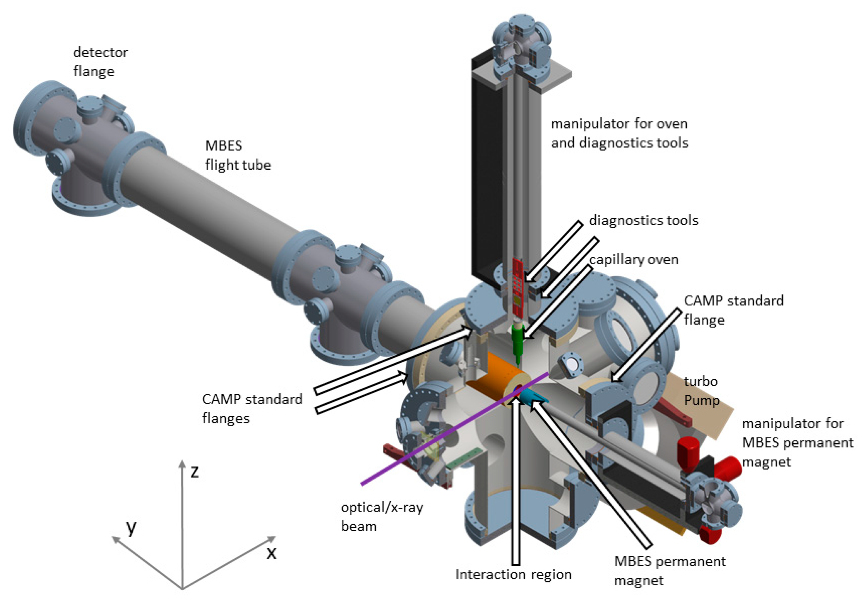
2.1. Overview and Vacuum System

Figure 1 shows an overview of the URSA-PQ instrument and its functionalities. In the current version, the sample is introduced by either backfilling the vacuum vessel or using a capillary oven. In this paper, the former is used to characterize the MBES, and the latter is used with 2-thiouracil to evaluate the time resolution. The interaction region is defined by the crossing point of the optical and X-ray beams overlapping with the region of highest sensitivity of the MBES. Molecules in the interaction region are excited by an optical laser pulse, in this case a 266 nm UV pulse, and subsequently probed by an X-ray pulse. Optical and X-ray pulses are focused by separate mirrors and combined inside the beamline by a mirror having a hole for X-ray transmission. The UV beam is set on side or top of the hole to avoid power losses. The tunable X-rays can induce a resonant core-to-valence excitation and/or non-resonant ionization. The resulting photo- and Auger electrons are then efficiently guided by the MBES’s magnetic field arrangement along a flight tube of 1.7 m length to a micro-channel-plate (MCP) detector. The time-of-flight of the electrons is measured and converted to electron kinetic energy. The apparatus is designed in a modular way that also allows upgrades at later times, the usage of different measurement devices from the FLASH environment and other types of sample delivery systems. The desired high flexibility is achieved by designing the central vacuum vessel as a customized six-way cross (see Figure 2), following the most critical dimensions of the permanent CAMP instrument situated at FLASH 1.
An overview of the instrument is shown in Figure 2. A central cross serves as the light-matter interaction chamber. A manipulator is mounted vertically (z-direction), holding the capillary oven molecular source and diagnostics tools on top of that source. Either one two of the devices (oven or diagnostics tools) can be brought into the center and thus the interaction region of the instrument. Shown in the positive y-direction is the MBES spectrometer flight tube with the MCP detector at the end. The manipulator holding a permanent magnet in the negative y-direction provides the up to 1 Tesla strong B-field of the MBES. The optical and X-ray beams travel in the x-direction, entering by the center flange, through the interaction region in the center of the cross to the center flange at the end.
The central cross of the instrument has three flanges (top in z-direction and left, right in ± y direction) that adhere to the CAMP instrument dimensions concerning flange size (DN 250 CF) and distance of flanges from the interaction region. For the front port where the FEL enters, the chamber is kept at short distance to the interaction region (280 mm) to support short focal lengths of the beamline. Breadboards are welded to the bottom of this port and the rear port to allow the incorporation of in-vacuum equipment such as incoupling optics and diagnosis tools. The floor facing port (−z direction) can be used for a LN2 cold trap (not shown here). A 1300 l/s turbomolecular pump is attached to a flange facing 45 degrees downwards. A variety of smaller flanges (DN40 to DN100) face the chamber center at the diagonals, or are located at the sides of the cross’s arms. Notably, three DN40 flanges at the entrance arm may be used for baffles. The vacuum apparatus is mounted on a movable frame (not shown here) that allows height and level adjustment by means of four legs. To simplify the alignment of the chamber axis to the FEL beam, the frame is equipped with a motorized x-y-stage and a manual rotation stage with the vertical axis below the connection to the beamline. In this way, the frame can be easily aligned to the path of the FEL beam. The motors of the frame, and the capillary oven magnet manipulators are controlled by a programmable logic controller (PLC).

2.2. Integration at the FLASH FL 24 Beamline

For the results presented here, the URSA-PQ chamber was integrated at FL 24 at FLASH 2 in Deutsches Elektronen Synchrotron (DESY), Hamburg, Germany. The beamline is equipped with bendable Kirkpatrick–Baez (KB) optics [24]. The distance from the KB optics to the interaction region in our experiment is 2.1 m.
The focus position of the X-rays can be manipulated within the chamber by using the KB degrees of freedom. We chose to have the focus beyond the interaction region, as we did want to maximize the number of X-ray photons on target without introducing X-ray nonlinearities. At about 90 cm in front of the interaction region, after the KB optics, the UV beam is coupled in by a 45 degree high reflectivity plane mirror for 266 nm wavelength. This mirror has a central hole for the X-ray beam to pass through. The optical beam is reflected from a position below the center hole, and steered up so that the two beams cross in the interaction region of the MBES.
The control and monitoring of the setup’s hardware, such as motor position, oven temperature and chamber pressure is handled by an industrial PLC system working in tandem with a UNIX server. All safety and/or time-sensitive tasks, such as vacuum valves control or high voltage interlocks, are managed by the PLC in a closed loop in order to ensure real-time responsivity. The UNIX server offers a server-client interface that allows multiple operators to monitor and control the system status from different terminals through the use of a purpose-built graphical user interface that connects to the server through a Python API (application program interface).
Integration with the DESY DOOCS (distributed object oriented control system) framework is seamlessly handled by the UNIX server. Experiment parameters such as chamber pressure and MCP voltages are constantly pushed to DOOCS for storage, allowing for later correlation of the chamber parameters with the experimental data. Moreover, the raw experimental data is retrieved from DOOCS and processed in real time. The data is sliced into single-shot traces, separating UV-pumped from non-pumped shots and averaged over a controllable time window. It is then made available to users for visualization (through a purpose built utility) or online analysis (through the python API). A real time calibrated time-of-flight to electron kinetic energy conversion of the measured traces is also provided through the API. After the experiment, all recorded data are available to the user group for offline analysis as hdf5 data files through the standard DESY channels.

2.3. Diagnostics and Oven

We have implemented a diagnostic paddle that is located on top of the oven on the same manipulator (see Figure 2), allowing for precise positioning inside the interaction region of the MBES spectrometer. The diagnostic paddle hosts a number of tools used for spatial as well as temporal characterization.
The spatial diagnostics serve to spatially overlap the UV and X-ray beams in the interaction region, as well as estimating the beam size. We use a 0.2 mm thick, 25 mm diameter YAG screen, possessing a matte, sandblasted surface. The screen is externally viewed through a vacuum window with the aid of a long working distance lens.
For timing diagnostics, we use a fast AXUV-type diode on a subminiature version A (SMA) connector that is not directly illuminated, but by a highly-attenuated beam created using solid filters which are moved in and out. The beam hits the mounting rim of the diode and only scattered light hits the active area in our case. We illuminate it separately with the optical and X-ray pulses. These signals are viewed on a 13 GHz bandwidth oscilloscope. The X-ray induced trace is saved as reference on the scope and the delay of the optical pulse is manipulated by a delay stage such that the rising edges of the two signals overlap. This strategy allows us to temporally overlap the optical and X-ray pulses with a sub 100 ps accuracy. Temporal overlap on the femtosecond scale is achieved using photo or Auger electrons of atoms or molecules shown later in this paper.
We use a resistively-heated capillary oven that we developed some years ago and successfully used before as a sample source at the linac coherent light source (LCLS) [16,18,21,25,26] as well as with high harmonic vacuum ultraviolet sources [27,28]. The oven consists of a body, a cap that is screwed on after filling the main body with a solid molecular sample, and a capillary tip. All components are made from aluminum. The three parts are separately heated using thin-film sheet heaters. The temperatures of the three sections are monitored using thermocouples and we control the heating current using a proportional-integral-derivative PID feedback circuit implemented on the control computer. The sample density has been once tested with the nucleobase thymine and can reach up to 1012 molecules/cm3 [21]. The capillary reduces the angular width of the beam compared to usual effusive sources and we have measured the full width at half maximum (FWHM) of 10 degrees when operating in the 1011 molecules/cm3 density regime [21].

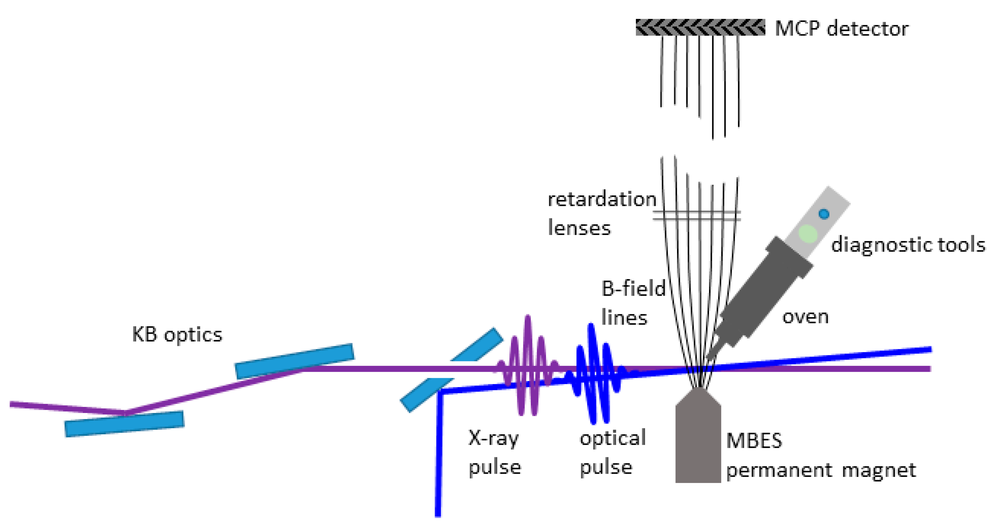
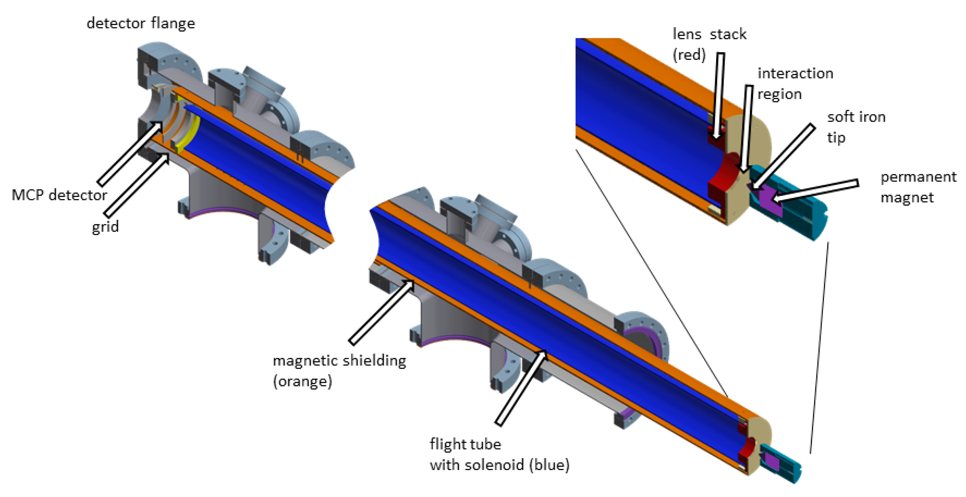
2.4. Magnetic Bottle Electron Spectrometer

The magnetic bottle time-of-flight electron spectrometer (MBES) has a high collection efficiency, covering up to the full 4π solid angle [26]. Thus, a large number of electrons can be efficiently detected, which is especially important in experiments with dilute samples. The magnetic bottle spectrometer is characterized by a strong and inhomogeneous magnetic field of about 1 Tesla at the interaction region, which joins onto a much weaker (~1 mT), homogeneous magnetic field created by a solenoid around the flight tube. Electrons ejected in the interaction region into any direction are thus confined into the flight tube. The time-of-flight (TOF) of the electrons from the interaction region to detection is determined and subsequently transformed into kinetic energy.
Our specific design is illustrated in Figure 3. A vacuum tube with DN160 flanges houses the flight tube, which is protected from external magnetic fields by a µ-metal shield. Wound onto the flight tube, a solenoid is generating the weak homogeneous field along the electron flight path. The coil has 1450 windings and is fed by a current of 400 mA producing a magnetic field of around 0.4 mT. Winding the coil directly on the flight tube has the advantage that the solenoid can be brought close to the interaction region. In addition, the design allows that the whole instrument can be taken out of the main chamber by unbolting a single DN 250 flange at the central cross. Close to the interaction region, right at the entrance of the flight tube, a stack of electrostatic lenses can be used to retard/repel the electrons. A permanent magnet with a soft iron pole tip generates the strong, inhomogeneous field in the interaction region. The space available at the beamline is used efficiently to maximize the instruments resolution, resulting in an optimal flight tube length of 1.7 m.
The transition from the inhomogeneous to homogeneous field occurs over a short distance of about 10 cm. The lens stack is placed inside the front of the flight tube, at the beginning of the homogeneous part of the magnetic field. At this point, the momentum in direction of the center axis of the flight tube is approximately equal for electrons of equal kinetic energy.
The permanent magnet of the instrument is mounted in a temperature-controlled holder on a manipulator. By this construction, the magnet can be brought close to the interaction region as well as retracted if other equipment is brought into the interaction region, such as a diode or a Ce-YAG screen. Elevated temperatures of 60 °C generally prevent sample building up on the magnet tip and introducing electrostatic inconsistencies.
The detector assembly (purchased from Roentdek Handels GmbH) consists of a grid, followed by a chevron MCP stack with an 80 mm diameter and an anode. The grid is held at the potential of the flight tube (i.e., the retardation potential). The electrons are then accelerated towards the front MCP by a +300 V potential change over 3 mm. Subsequently, the electrons are multiplied by the MCP arrangement using a potential on the MCP backside of 1950 V. The anode, used for picking up the signal is held at 2300 V. The signal is picked up by a high-pass filter and sent to a 12 bit analog-digital converter, which we use at a sample rate of 2Gs. A single electron pulse has a width of 10 ns. The data we present in this paper has been accumulated in the integration mode, i.e., all individual TOF traces have been added. Alternatively, for lower electron yield, individual electron hits can be identified by using a (software) constant fraction discriminator and then added individually to a TOF array.
We transform spectra taken in the TOF domain to the kinetic energy domain by the following procedure. The distance from the interaction region to the detector is divided into three parts. The electric potential in these parts is treated as a step function and the lengths are taken from the CAD drawing of the spectrometer but refined in the calibration by fitting to Auger electron features. In the first part, the electrons are traveling with their original kinetic energy for a distance of 90 mm from the interaction region to the flight tube entrance. In the second part through the flight tube, which is 1694 mm long, their kinetic energy is reduced by the retardation voltage. We fit these distances based on observed electron spectra in the calibration procedure shown below. In the 3-mm-long final part from the flight tube to the detector, their kinetic energy is increased by 300 V.
After axis transformation from TOF to kinetic energy, the signal strength is multiplied by a Jacobian function which corrects for the non-linear mapping of bins from the TOF domain and the kinetic energy domain.

3. Results and Discussion

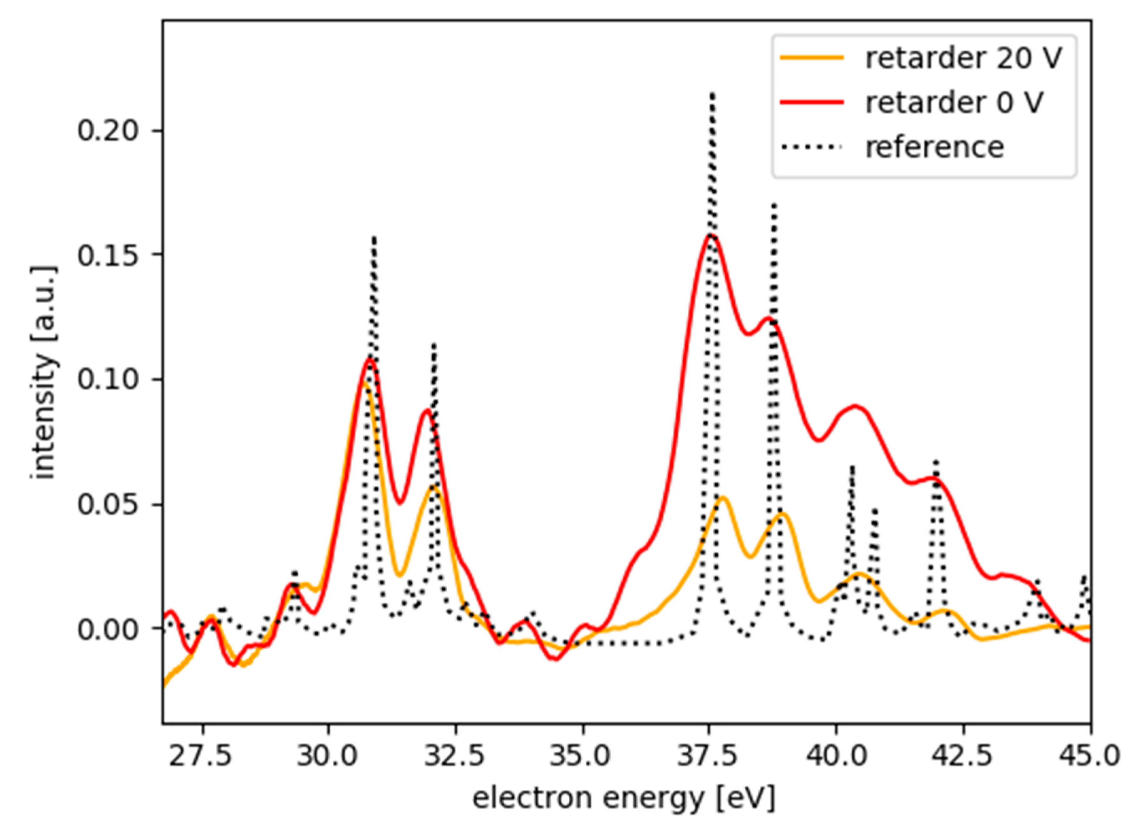
3.1. MBES Energy Resolution

The spectrometer has been calibrated with the Kr M4,5NN Auger lines, appearing in the kinetic energy range shown in Figure 4. The background pressure in the interaction region was 2 × 10⁻⁷ mbar before filling in Kr, although much lower pressures in the 10−9 mbar range have been reached by pumping for longer times and baking. We backfilled the chamber with Kr gas at a pressure of 5.5 × 10⁻⁷ mbar for calibration purposes.
We chose an FEL photon energy of 270 eV; the spectral jitter was on the order of 2% as observed by an inline diagnostic instrument at the beamline [30]. The nonresonant Auger lines however are not affected by the spectral jitter of the light source. The permanent magnet of the spectrometer was moved close to the interaction region and scanned vertically to and horizontally along the FEL beam to optimize the position for highest electron signal. A halo of scattered light around the laser focus prohibited distances of the magnet tip to laser focus to be smaller than 4 mm. Even a small amount of scattered light produced many more photoelectrons from the solid magnet tip than from the gas in the real focus because of the orders of magnitude lower density of our gas compared to solid matter.
The Auger spectra used for calibration are shown in Figure 4. The red line is recorded using a retardation potential of 0 V. The black reference spectrum is obtained from Werme et al. [29]. One can clearly identify the two different groups of Kr M4,5NN Auger lines in our spectra. In the higher energy group, we identify the two lines at 37.7 and 38.7 eV as two separate lines. This results in an energy resolution without retardation of ΔE/E ≅ 1/40. The kinetic energy spectrum with 20 V retardation voltage (orange) shows deeper modulation indicating higher energy resolution, as the kinetic energy decreased.
We now discuss the resolution-limiting factors in the calibration measurements. We note a large background in the kinetic energy range between 35 and 37.5 eV. This results from a saturation of the detector due to a large amount of electron counts per X-ray pulse. In the TOF-spectrum, the group of Auger electrons between 37 and 42.5 eV hit the detector at early times and thereby produces a long lasting background of several nanoseconds. By the time the next group between 30 and 32 eV hits the detector, this signal has decayed. This memory effect in the detector certainly degrades the resolution as background accumulates in a group of Auger lines. This issue can be easily solved by reducing the FEL pulse energy or the Kr pressure; in the following experimental runs for 2-thiouracil, we had adjusted pressure as well as FEL pulse energy accordingly.
A single electron pulse coupled out at the detector-anode has a width of 10 ns and is completely symmetric, i.e., the rising edge is not shorter than the falling edge. As mentioned above, we used the system in ‘integration-mode’ by adding up individual traces from the detector. The 10 ns pulse width in TOF corresponds to 0.5 eV of energy resolution in the kinetic energy range around 20 eV. The experimental energy resolution of 1/40 corresponds to a 10 ns time-interval at a TOF of 300 ns (kinetic energy of 101 eV).
A possibility to improve the time resolution would be the reduction of the number of electrons hitting the detector. This would reduce the detector saturation and therefore accumulated background in the different groups. Another important advantage would be the possibility to identify individual electrons hitting the detector. This will allow for edge detection, for instance via a constant fraction discriminator. In this case, the resolution is fundamentally limited by the sample interval of the analog-to-digital converter (ADC), which is 500 ps in our case. In analogy to the resolution limit of 10 ns, the 500 ps would correspond to an energy resolution of 0.03 eV in the energy range of 20 eV. However, there is also the turn-around time of the electrons emitted initially away from the detector, which will also limits the resolution [20].

3.2. Temporal Resolution

We now investigate the temporal resolution in the optical pump—these are X-ray probe experiments. As mentioned above, we initially determined the coarse temporal overlap by monitoring a fast-diode response, induced by UV and X-ray pulses, on an oscilloscope. The setup had an accuracy in the sub-100 ps domain. As 100 ps resolution is not sufficient for the experiments, more accurate information on the temporal overlap, as well as the temporal resolution achievable by this setup, we performed measurements of photoelectron signals of molecules using the URSA instrument. We used the molecule 2-thiouracil (C4H4N2OS), as this has been the molecule of interest for our first beamtime utilizing this instrument. Thionucleobases are interesting as they show an efficient relaxation to long-lasting triplet states after UV excitation, thereby showing different behavior compared to canonical nucleobases, which relax relatively quickly to the ground state [31].
Figure 5a shows a core level photoelectron spectrum of 2-thiouracil illuminated by X-ray photons of 272 eV mean-photon-energy. The pulses have less than 1% mean- photon-energy-jitter and a relative bandwidth of 1–1.5%. Shown in this particular part of the spectrum is the 2p-photoline of sulfur at 103.5 eV kinetic energy. This line should be spin-orbit split resulting in the j = 3/2 and 1/2 components with an energy spacing of 1.2 eV [32], however already the photon energy resolution is not sufficient to resolve that splitting. The small shoulder visible on the lower kinetic energy side at 95–97 eV is a satellite structure that accompanies the main 2p photoline (as, for instance, previously documented for sulfur on surfaces [33]).
Upon UV excitation, the main photoline shifts towards lower kinetic energies, due to the molecular dynamics setting in immediately. The molecular origin for this observation will be discussed in detail in a separate paper. Here, we use this feature to determine the temporal overlap with sub-ps precision, and the overall time resolution of the experiment itself. We take here the difference spectrum (not shown), calculate its absolute value |UVon − UVoff| as a measure for the UV induced change in the spectrum. This observable as a function of relative delay between UV-pump and X-ray-probe pulse is shown by the blue dots in Figure 5b, together with a theoretical fit shown by the orange line. The fit function includes a Gaussian describing the time-resolution, convoluted with two exponential decays (see for instance Equation (3) in Reference [34]). The second exponential decay is longer than 100 ps and has limited influence on the data in the delay window shown. The faster exponential decay of (230 ± 30) fs describes some molecular dynamics. Most interesting in the context here is the Gaussian time-resolution function. We actually determined the relative time-overlap by the maximum of this Gaussian, which can be done with a sub-10 fs accuracy. The Gaussian time resolution when correcting data using the beam arrival monitor [35] has a FWHM of σ T R = (190 ± 10) fs.
There are different contributions to the origin of the time-resolution known in the literature which sum up geometrically to the final time resolution σ T R = σ U V L 2 + σ F E L 2 + σ F E L t r a i n 2 + σ U V L t r a i n 2 + σ F E L U V L j i t t e r 2 , where σ U V L is the UV pulse length, σ F E L the X-ray pulse length, σ F E L t r a i n the intra-train jitter of the X-ray pulses within the macro-bunch, σ U V L t r a i n the intra-train jitter of the UV pulses within the macrobunch and σ F E L U V L j i t t e r the relative timing jitter of X-ray and UV laser pulses [36]. The UV pulse duration has been determined to be σ U V L = 80 fs by a frequency resolved optical gating (FROG) measurement [37]. Subtracting the UV pulse duration geometrically yields 170 fs Gaussian FWHM total for all other components. The other components have been estimated with σ F E L t r a i n = σ U V L t r a i n = 30–40 fs and σ F E L U V L j i t t e r = 70 fs [38,39]. Subtracting all these components out delivers a remaining X-ray pulse duration in the experiment in the region of about 150 fs. Taking all these components into account results in a remaining X-ray pulse duration in the experiment on the order of 150 fs. However, we would expect a sub-100 fs X-ray pulse duration for this bunch charge. The discrepancy could possibly be attributed to a higher jitter compared to past experiments and longer term drifts.

4. Conclusions

We presented the new URSA-PQ instrument which is now available for general users at the FLASH FEL facility. We described its major design features and its flexibility because of its adherence to CAMP instrument dimensions. The instrument is already equipped with a molecular source and a magnetic bottle spectrometer, allowing for ultrafast X-ray probe studies of photoexcited molecular dynamics. We demonstrated the current spectral resolution of the MBES of 1/40 using the M4,5NN Auger decay of Kr in the range of 30–45 eV electron energy. This can be improved further by treating electron signals digitally using a combination of an edge finder and time-to-digital conversion. We investigated the time-resolution in conjunction with the FLASH 2 pump-probe laser delivering 266 nm pulses at FL 24. For that purpose, we used a UV-induced shift of the sulfur 2p photoelectron line of the molecules 2-thiouracil. We find a temporal resolution of 190 fs using photoelectron features from UV excited 2-thiouracil.

Author Contributions

Instrument design, J.M. and M.G.; MBES design, J.M. with help of R.J.S. and R.F.; realization of the instrument: J.M., D.M., F.L., M.N., M.S.R., S.D., M.G.; instrument software, F.L. with help of J.M., performing experiments, all authors; analyzing data, F.L., D.M. with help of M.G.; writing paper: J.M., F.L., D.M. and M.G.; comments and suggestions on the paper drafts, all authors. All authors have read and agreed to the published version of the manuscript.

Funding

The URSA-PQ instrument and the position of J.M. was funded by the German Federal Ministry for Education and Research (BMBF) under ‘Verbundforschungsprojekt 05K16IP1′. The Potsdam Research Group is funded by a Lichtenberg Professorship of the Volkswagen-Stiftung. We acknowledge DFG funding via grant GU 1478/1-1. We acknowledge DESY (Hamburg, Germany), a member of the Helmholtz Association HGF, for the provision of experimental facilities. Part of this research was carried out at FLASH2. R.F. and R.J.S. received funding from the Swedish Research Council and the Knut and Alice Wallenberg Foundation, Sweden. We acknowledge the support of the Deutsche Forschungsgemeinschaft and Open Access Publishing Fund of University of Potsdam.

Acknowledgments

We acknowledge S. Alisauskas, F. Calegari, B. Manschwetus, M. Kuhlmann, T. Mazza, A. Trabattoni, M. Wallner and T. J. A. Wolf for participating in the experiments on thiouracil.

Conflicts of Interest

The authors declare no conflict of interest. The funders had no role in the design of the study; in the collection, analyses, or interpretation of data; in the writing of the manuscript, or in the decision to publish the results.

References

  1. Yarkony, D. Diabolical conical intersections. Rev. Mod. Phys. 1996, 68, 985–1013. [Google Scholar] [CrossRef]
  2. Levine, B.G.; Martínez, T.J. Isomerization through Conical Intersections. Annu. Rev. Phys. Chem. 2007, 58, 613–634. [Google Scholar] [CrossRef] [PubMed]
  3. Matsika, S.; Krause, P. Nonadiabatic Events and Conical Intersections. Annu. Rev. Phys. Chem. 2011, 62, 621–643. [Google Scholar] [CrossRef] [PubMed]
  4. Domcke, W.; Yarkony, D.R.; Köppel, H. Conical Intersections Electronic Structure, Dynamics and Spectroscopy; World Scientific Publishing Company: Singapore, 2011; ISBN 978-981-4313-45-2. [Google Scholar]
  5. Polli, D.; Altoè, P.; Weingart, O.; Spillane, K.M.; Manzoni, C.; Brida, D.; Tomasello, G.; Orlandi, G.; Kukura, P.; Mathies, R.A.; et al. Conical intersection dynamics of the primary photoisomerization event in vision. Nature 2010, 467, 440–443. [Google Scholar] [CrossRef] [PubMed]
  6. Crespo-Hernández, C.E.; Cohen, B.; Hare, P.M.; Kohler, B. Ultrafast Excited-State Dynamics in Nucleic Acids. Chem. Rev. 2004, 104, 1977–2020. [Google Scholar] [CrossRef]
  7. Middleton, C.T.; de La Harpe, K.; Su, C.; Law, Y.K.; Crespo-Hernández, C.E.; Kohler, B. DNA Excited-State Dynamics: From Single Bases to the Double Helix. Annu. Rev. Phys. Chem. 2009, 60, 217–239. [Google Scholar] [CrossRef] [Green Version]
  8. Schreier, W.J.; Gilch, P.; Zinth, W. Early Events of DNA Photodamage. Annu. Rev. Phys. Chem. 2015, 66, 497–519. [Google Scholar] [CrossRef] [PubMed]
  9. Improta, R.; Santoro, F.; Blancafort, L. Quantum Mechanical Studies on the Photophysics and the Photochemistry of Nucleic Acids and Nucleobases. Chem. Rev. 2016, 116, 3540–3593. [Google Scholar] [CrossRef]
  10. Dörner, R.; Mergel, V.; Jagutzki, O.; Spielberger, L.; Ullrich, J.; Moshammer, R.; Schmidt-Böcking, H. Cold Target Recoil Ion Momentum Spectroscopy: A “momentum microscope” to view atomic collision dynamics. Phys. Rep. 2000, 330, 95–192. [Google Scholar] [CrossRef]
  11. Ullrich, J.; Moshammer, R.; Dorn, A.; Dorner, R.; Schmidt, L.P.H.; Schmidt-Böcking, H. Recoil-ion and electron momentum spectroscopy: Reaction-microscopes. Rep. Prog. Phys. 2003, 66, 1463–1545. [Google Scholar] [CrossRef]
  12. Stapelfeldt, H.; Seideman, T. Colloquium: Aligning molecules with strong laser pulses. Rev. Mod. Phys. 2003, 75, 543. [Google Scholar] [CrossRef] [Green Version]
  13. McFarland, B.K.; Farrell, J.P.; Bucksbaum, P.H.; Gühr, M. High Harmonic Generation from Multiple Orbitals in N2. Science 2008, 322, 1232. [Google Scholar] [CrossRef] [Green Version]
  14. Filsinger, F.; Meijer, G.; Stapelfeldt, H.; Chapman, H.N.; Kuepper, J. State- and conformer-selected beams of aligned and oriented molecules for ultrafast diffraction studies. Phys. Chem. Chem. Phys. 2011, 13, 2076–2087. [Google Scholar] [CrossRef] [Green Version]
  15. Siegbahn, K. ESCA Applied to Free Molecules; North-Holland Pub. Co.: Amsterdam, The Netherlands, 1969; ISBN 0-7204-0160-7. [Google Scholar]
  16. Wolf, T.J.A.; Myhre, R.H.; Cryan, J.P.; Coriani, S.; Squibb, R.J.; Battistoni, A.; Berrah, N.; Bostedt, C.; Bucksbaum, P.; Coslovich, G.; et al. Probing ultrafast ππ*/nπ* internal conversion in organic chromophores via K-edge resonant absorption. Nat. Commun. 2017, 8, 29. [Google Scholar] [CrossRef] [Green Version]
  17. Ehlert, C.; Gühr, M.; Saalfrank, P. An efficient first principles method for molecular pump-probe NEXAFS spectra: Application to thymine and azobenzene. J. Chem. Phys. 2018, 149, 144112. [Google Scholar] [CrossRef]
  18. McFarland, B.K.; Farrell, J.P.; Miyabe, S.; Tarantelli, F.; Aguilar, A.; Berrah, N.; Bostedt, C.; Bozek, J.D.; Bucksbaum, P.H.; Castagna, J.C.; et al. Ultrafast X-ray Auger probing of photoexcited molecular dynamics. Nat. Commun. 2014, 5, 4235. [Google Scholar] [CrossRef] [Green Version]
  19. Wolf, T.; Holzmeier, F.; Wagner, I.; Berrah, N.; Bostedt, C.; Bozek, J.; Bucksbaum, P.; Coffee, R.; Cryan, J.; Farrell, J.; et al. Observing Femtosecond Fragmentation Using Ultrafast X-ray-Induced Auger Spectra. Appl. Sci. 2017, 7, 681. [Google Scholar] [CrossRef]
  20. Kruit, P.; Read, F.H. Magnetic field paralleliser for 2π electron-spectrometer and electron-image magnifier. J. Phys. E Sci. Instrum. 1983, 16, 313–324. [Google Scholar] [CrossRef]
  21. McFarland, B.K.; Berrah, N.; Bostedt, C.; Bozek, J.; Bucksbaum, P.H.; Castagna, J.C.; Coffee, R.N.; Cryan, J.P.; Fang, L.; Farrell, J.P.; et al. Experimental strategies for optical pump – soft x-ray probe experiments at the LCLS. J. Phys. Conf. Ser. 2014, 488, 012015. [Google Scholar] [CrossRef] [Green Version]
  22. Ferro, D.; Bencivenni, L.; Teghil, R.; Mastromarino, R. Vapour pressures and sublimation enthalpies of thymine and cytosine. Thermochim. Acta 1980, 42, 75–83. [Google Scholar] [CrossRef]
  23. Strueder, L.; Epp, S.; Rolles, D.; Hartmann, R.; Holl, P.; Lutz, G.; Soltau, H.; Eckart, R.; Reich, C.; Heinzinger, K.; et al. Large-format, high-speed, X-ray pnCCDs combined with electron and ion imaging spectrometers in a multipurpose chamber for experiments at 4th generation light sources. Nucl. Instrum. Methods Phys. Res. Sect. A-Accel. Spectrom. Detect. Assoc. Equip. 2010, 614, 483–496. [Google Scholar] [CrossRef] [Green Version]
  24. Raimondi, L.; Manfredda, M.; Mahne, N.; Cocco, D.; Capotondi, F.; Pedersoli, E.; Kiskinova, M.; Zangrando, M. Kirkpatrick–Baez active optics system at FERMI: System performance analysis. J. Synchrotron Rad. 2019, 26, 1462–1472. [Google Scholar] [CrossRef]
  25. Zhaunerchyk, V.; Kamińska, M.; Mucke, M.; Squibb, R.J.; Eland, J.H.D.; Piancastelli, M.N.; Frasinski, L.J.; Grilj, J.; Koch, M.; McFarland, B.K.; et al. Disentangling formation of multiple-core holes in aminophenol molecules exposed to bright X-FEL radiation. J. Phys. B At. Mol. Opt. Phys. 2015, 48, 244003. [Google Scholar] [CrossRef] [Green Version]
  26. Sanchez-Gonzalez, A.; Barillot, T.R.; Squibb, R.J.; Kolorenč, P.; Agaker, M.; Averbukh, V.; Bearpark, M.J.; Bostedt, C.; Bozek, J.D.; Bruce, S.; et al. Auger electron and photoabsorption spectra of glycine in the vicinity of the oxygen K-edge measured with an X-FEL. J. Phys. B At. Mol. Opt. Phys. 2015, 48, 234004. [Google Scholar] [CrossRef] [Green Version]
  27. Koch, M.; Wolf, T.J.A.; Gühr, M. Understanding the modulation mechanism in resonance-enhanced multiphoton probing of molecular dynamics. Phys. Rev. A 2015, 91. [Google Scholar] [CrossRef] [Green Version]
  28. Wolf, T.J.A.; Parrish, R.M.; Myhre, R.H.; Martínez, T.J.; Koch, H.; Gühr, M. Observation of Ultrafast Intersystem Crossing in Thymine by Extreme Ultraviolet Time-Resolved Photoelectron Spectroscopy. J. Phys. Chem. A 2019, 123, 6897–6903. [Google Scholar] [CrossRef] [PubMed]
  29. Werme, L.O.; Bergmark, T.; Siegbahn, K. The High Resolution L2,3 MM and M4,5 NN Auger Spectra from Krypton and M4,5 NN and N4,5 OO Auger Spectra from Xenon. Phys. Scr. 1972, 6, 141–150. [Google Scholar] [CrossRef]
  30. Braune, M.; Buck, J.; Kuhlmann, M.; Grunewald, S.; Düsterer, S.; Viefhaus, J.; Tiedtke, K. Non-invasive online wavelength measurements at FLASH2 and present benchmark. J. Synchrotron Rad. 2018, 25, 3–15. [Google Scholar] [CrossRef] [Green Version]
  31. Arslancan, S.; Martínez-Fernández, L.; Corral, I. Photophysics and Photochemistry of Canonical Nucleobases’ Thioanalogs: From Quantum Mechanical Studies to Time Resolved Experiments. Molecules 2017, 22, 998. [Google Scholar] [CrossRef]
  32. Giuliano, B.M.; Feyer, V.; Prince, K.C.; Coreno, M.; Evangelisti, L.; Melandri, S.; Caminati, W. Tautomerism in 4-Hydroxypyrimidine, S-Methyl-2-thiouracil, and 2-Thiouracil. J. Phys. Chem. A 2010, 114, 12725–12730. [Google Scholar] [CrossRef]
  33. Föhlisch, A.; Feulner, P.; Hennies, F.; Fink, A.; Menzel, D.; Sanchez-Portal, D.; Echenique, P.M.; Wurth, W. Direct observation of electron dynamics in the attosecond domain. Nature 2005, 436, 373–376. [Google Scholar] [CrossRef] [PubMed]
  34. Beckwith, J.S.; Rumble, C.A.; Vauthey, E. Data analysis in transient electronic spectroscopy—An experimentalist’s view. Int. Rev. Phys. Chem. 2020, 39, 135–216. [Google Scholar] [CrossRef]
  35. Savelyev, E.; Boll, R.; Bomme, C.; Schirmel, N.; Redlin, H.; Erk, B.; Düsterer, S.; Müller, E.; Höppner, H.; Toleikis, S.; et al. Jitter-correction for IR/UV-XUV pump-probe experiments at the FLASH free-electron laser. New J. Phys. 2017, 19, 043009. [Google Scholar] [CrossRef] [Green Version]
  36. Dziarzhytski, S.; Biednov, M.; Dicke, B.; Wang, A.; Miedema, P.S.; Engel, R.Y.; Schunck, J.O.; Redlin, H.; Weigelt, H.; Siewert, F.; et al. The TRIXS end-station for femtosecond time-resolved resonant inelastic x-ray scattering experiments at the soft x-ray free-electron laser FLASH. Struct. Dyn. 2020, 7, 054301. [Google Scholar] [CrossRef] [PubMed]
  37. Trebino, R. Frequency-Resolved Optical Gating: The Measurement of Ultrashort Laser Pulses; Springer Science & Business Media: New York, NY, USA, 2000; ISBN 978-1-4613-5432-1. [Google Scholar]
  38. Schulz, S.; Grguraš, I.; Behrens, C.; Bromberger, H.; Costello, J.T.; Czwalinna, M.K.; Felber, M.; Hoffmann, M.C.; Ilchen, M.; Liu, H.Y.; et al. Femtosecond all-optical synchronization of an X-ray free-electron laser. Nat. Commun. 2015, 6, 5938. [Google Scholar] [CrossRef]
  39. Schulz, S.; Czwalinna, M.K.; Felber, M.; Predki, P.; Schefer, S.; Schlarb, H.; Wegner, U. Femtosecond-precision synchronization of the pump-probe optical laser for user experiments at flash. In Proceedings of the Advances in X-ray Free-Electron Lasers ii: Instrumentation, Prague, Czech Republic, 17–19 April 2013; Tschentscher, T., Tiedtke, K., Eds.; Spie-int Soc Optical Engineering: Bellingham, WA, USA, 2013; Volume 8778. [Google Scholar]
Figure 1. Diagrammatic representation of the URSA-PQ (German for ‘Ultraschnelle Röntgenspektroskopie zur Abfrage der Photoenergiekonversion an Quantensystemen’, Engl. ‘ultrafast X-ray spectroscopy for probing photoenergy conversion in quantum systems’) instrument with its functionalities. The molecular sample is evaporated and guided into the interaction region by a capillary oven. An optical laser pulse excites the sample before a delayed X-ray pulse from the FLASH FEL, focused by a Kirkpatrick-Baez (KB) mirror set, probes the excited molecular ensemble. Photo- and Auger-electrons created by the light-matter interaction are guided by the magnetic field of the magnetic bottle electron spectrometer (MBES) towards a detector. The diagnostic tools for spatial and time-overlap can we driven into the interaction region.
Applsci 10 07882 g001
Figure 2. Design-drawing of the URSA-PQ (German for ‘Ultraschnelle Röntgenspektroskopie zur Abfrage der Photoenergiekonversion an Quantensystemen’, Engl. ‘ultrafast X-ray spectroscopy for probing photoenergy conversion in quantum systems’) instrument. The central body contains flanges that adhere to the standard defined by the CAMP-chamber in size as well as distance to the interaction region (marked). The capillary oven and diagnostic tools are mounted on a manipulator allowing for insertion of either device into the beam. The permanent magnet of the magnetic bottle electron spectrometer (MBES) sits on another manipulator to optimally overlap the region of highest sensitivity of the MBES with the interaction region of the optical and X-ray pulses. The 1.7 m long flight tube connects the main body to the detector flange housing the microchannel plate electron detector.
Applsci 10 07882 g002
Figure 3. Cut-down scheme of the magnetic bottle time of flight spectrometer, with the magnified area around the interaction region. The interaction region is defined by the overlap of the optical and X-ray pulse with the region of highest sensitivity of the MBES. The magnetic field in the interaction region is dominated by the permanent magnet having a tapered soft-iron pole piece on top. The strong, inhomogeneous magnetic field drops quickly to a weak, homogeneous solenoid field surrounding the flight tube, thus guiding the electrons from the interaction region towards the detector. A µ-metal tube (orange) around the flight-tube and solenoid assembly (blue) shields the long flight region from external magnetic fields. At the entrance of the flight tube, an electrostatic lens stack can be used to retard the electrons to optimally utilize the energy resolution at a mean kinetic energy of choice. The micro-channel-plate (MCP) detector assembly contains a grid at the front to accelerate electrons towards the first plate. The grid and lens stack are equipotential so that the electrons travel through the flight tube with constant velocity.
Applsci 10 07882 g003
Figure 4. Krypton M4,5NN Auger spectra recorded with the URSA-PQ instrument using 270 eV photons (red spectrum using a retardation of 0 V, orange spectrum using a retardation of 20 V). The spectra are recorded with a back-filled interaction chamber and converted from time-of-flight (TOF) to kinetic energy. The black spectrum from Reference [29] serves as a reference.
Applsci 10 07882 g004
Figure 5. (a) Experimental photoelectron spectrum showing the sulfur-2p photoline of 2-thiouracil taken with a photon energy of ~270 eV. (b) Increase of the absolute value in the difference signal |(UVon − UVoff)| as a function of pump-probe delay (blue dots) and fit by the model explained in the text (orange line).
Applsci 10 07882 g005
Publisher’s Note: MDPI stays neutral with regard to jurisdictional claims in published maps and institutional affiliations.

