1. Introduction
Additive manufacturing (AM) technologies enable the construction of complex parts, such as high-performance parts or highly customised and specific parts [
1,
2]. Production of parts providing features of almost every function and shape becomes feasible [
3]. Since part complexity and geometrical features have low impact on product cost and production time, construction of batches of parts different from the other becomes feasible. Moreover, the direct link between a computer aided design (CAD) model and a built part can be currently exploited in order to produce in a fast way both prototypes and end-use parts [
4].
Therefore, several technologies have been replaced by AM, even if this replacement requires dedicated redesign of product and process. In the past, other technological changes affected the production of parts and components: as an example, in the 2000s, the metal replacement (or metal-to-plastic replacement) started to be one of the main industrial trends [
5,
6], involving all the industrial fields, and it is still an ongoing trend. Similarly, but most recently, we can state that the same role is played by the AM technologies. These trends share the main common goal of making parts lighter and more efficient to be manufactured. Moreover, AM can further benefit from its integration with topology optimisation (TO), leading to complex morphologies and free form models, with an increase in product customisation.
Many industrial sectors have been positively influenced by AM, e.g., aerospace and automotive, as well as the medical field, which can mainly benefit from parts produced specifically for individual patient’s needs. Biomedical devices account for many applications [
7] as well as challenges concerning prosthetics and implants development, surgical and diagnostic aids and even tissue and organ engineering [
8,
9], occupational therapy and rehabilitation [
10,
11]. A further example is the development of customised assistive devices (ADs), with positive integration of AM and co-design approaches [
12]. All these changes open new frontiers as well as new drawbacks. With particular regards to a redesign process based on AM, the following main issues may occur [
13]:
Selection of redesign variants: The outputs of the TO consist of a great number of variants, which need to be managed and selected.
Optimised designs interpretation: A wide number of topologically optimised design alternatives usually occur due to the redesign loops during the workflow iterations, requiring the designer to evaluate and interpret them into CAD models.
Definition of product and process parameters: The designer is used to evaluate and optimise one parameter at a time or a single parameter category, considering separately functional and production requirements.
File exchange and data management during the workflow iterations: The entire workflow, from the first model to final job creation, involves different software tools that need different file formats (as inputs), requiring multiple conversions of file formats due to iterations during the design and the industrialisation tasks. An STL file is used as interchange file between different software: as a support for CAD modelling parts starting from the results of TO, for finite elements analysis (FEA) simulation, for industrialisation tasks in the AM preparation software, for AM process simulation.
These practises, common in the industry, highlight the need for approaches, methods and tools to support the product optimisation and, at the same time, the process optimisation, by identifying the best-developed solution. Therefore, to exploit the benefits offered by the AM implementation, the concurrent development of technology and its specific knowledge is urged. Thus, design for additive manufacturing (DfAM) of proper methods, systematic tools, objective guidelines and approaches, as well as their implementation and application, is fundamental [
14,
15,
16].
In this work, we share our experience with the development of a product redesign approach when replacing/changing the manufacturing technology and, then, its guiding design principles. As a case study, we focus on the development of an assistive device (AD), originally co-designed with patients, which failed some functional goals due to the original material and production process.
The paper is organised as follows: Firstly, the systematic method for the redesign of product is introduced in
Section 2;
Section 3 reports the case study and the tools involved; in
Section 4, the results of the redesign method implementation are discussed; finally, the conclusions are summarised in
Section 5.
2. Method
A product optimisation approach can be considered as a key phase of a general DfAM workflow [
17], as synthesised in
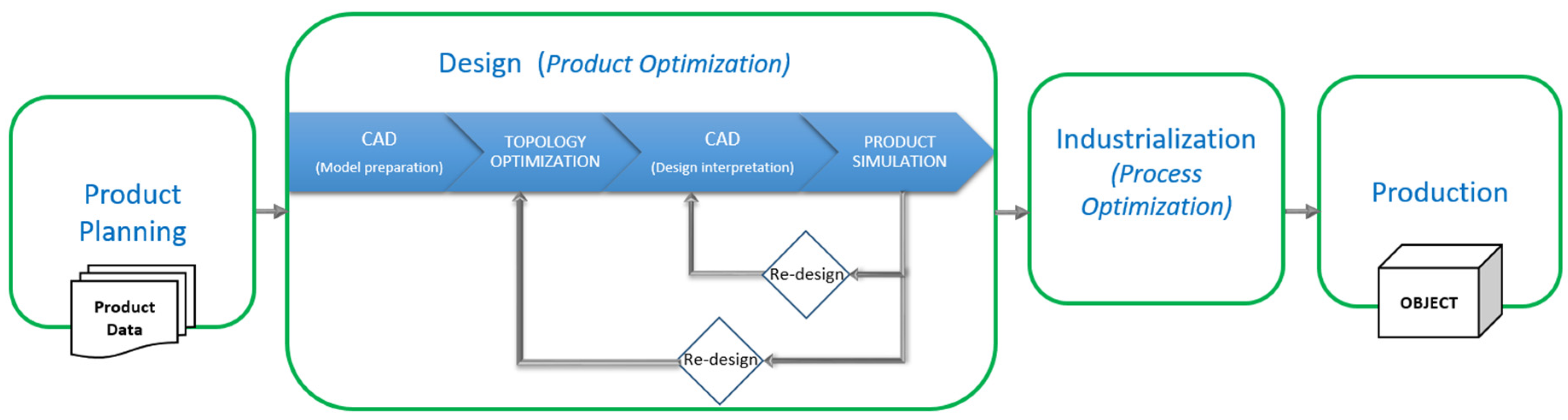
Figure 1. The workflow represents an iterative process based on product and process optimisation subjected to design and industrialisation constraints, aiming to exploit the potentials of the AM technology.
The workflow consists of four main phases: The product planning phase leads to the complete definition of the product data, considering design targets and constraints, and including testing results and users’ suggestions. Concerning the design phase, the product optimisation and validation tasks aim to achieve the established targets. In the industrialisation phase, process study and 3D printing preparation are mandatory, while additional optimisation can be performed. The production phase covers 3D printing and post-processing operations necessary to provide the user with the optimised product version.
Moreover, product optimisation can be obtained by implementing TO techniques [
14,
18] and is generally achieved through a series of redesigns. Both these operations are included among the most time-consuming activities and represent a complex research area due to automation needs [
19,
20]. Therefore, this phase can benefit from a systematic approach to better exploit the potentials offered by AM, while clarifying the decisional steps and speeding up the workflow.
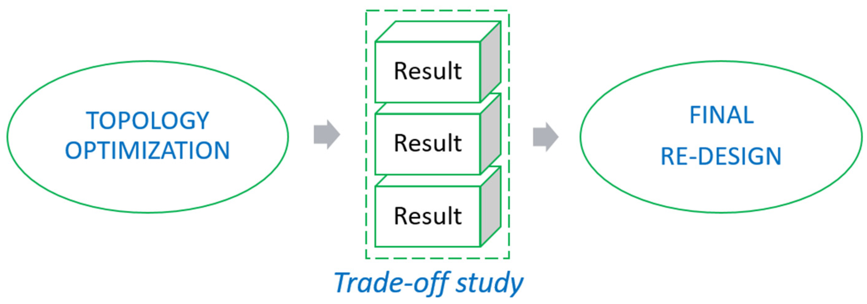
Figure 2 proposes a workflow that provides a design optimisation through a systematic concept selection-based approach [
21]. The aim is to perform a design solution exploration by using TO and subsequently defining results selection criteria. Results represent conceptual solutions generated from TO. Finally, by integrating the decisional process into a structured system called trade-off study, just one final redesign can occur in order to perform product optimisation.
To perform the concept selection step, data collected from analyses and simulation are processed into spreadsheets to create key performance indicators (KPIs) matrices. The evaluated elements can be related not only to the product features but also to the associated processes. By assigning scores and weights to KPIs and depending on the design specifications, the systematic concept selection-based approach can be performed and integrated into the general DfAM workflow. Furthermore, the approach can be extended from DfAM to product redesign and design optimisation, therefore considering in general different product variants, manufacturing technologies or further studies.
3. Case Study—Can Opener Assistive Device
In this section, we present the integration of the proposed method into a co-design approach for the development of assistive devices (ADs) and the selected case study is described and analysed, defining design objectives and constraints and detailing the optimisation approach.
3.1. Method Integration
The method adopted to exploit AM potentials for development of customised ADs is based on a systematic approach [
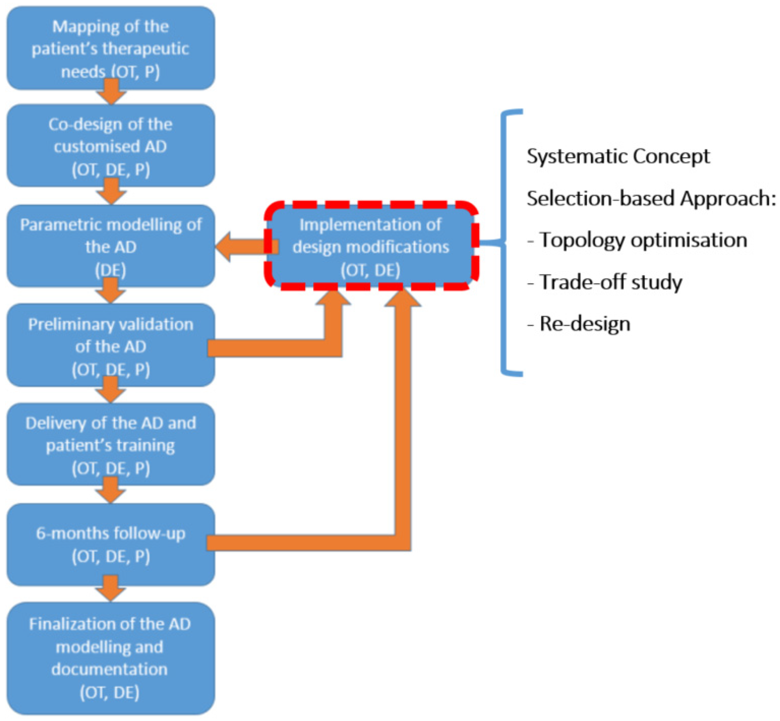
12]. Product customisation is made possible thanks to the patient’s involvement through a co-design approach. The workflow is composed by sundry different tasks to be performed in sequence. These include mapping of the patient’s needs, co-design phase, parametric modelling of the AD, validation process, finalisation of models and documentation (
Figure 3). Two iterative redesign loops can occur to optimise the AD design. The former is based on results of the patient’s preliminary validation of the first prototype. The latter can be performed after the 6-month follow-up and long-term use verification. Redesign loops provide implementation of design modifications required on morphological and/or functional features. A possible execution can be based on direct patient’s inclusion for AD improvement [
22], especially if functional targets are achieved, whereas ergonomic or aesthetic ones are not satisfied. Otherwise, at each of these stages, a redesign for AM that provides product optimisation (including process/material replacement) can be required to achieve the expected functional targets. For example, after prototyping and testing, some critical issues and suggestions of improvements can emerge and, at this point, product optimisation can occur.
3.2. Original Part Analysis: Possible Issues
The original can opener may be functionally decomposed into two parts. The first interfacing with the can and its tab, and the second with the patient’s hand (i.e., the handle) [
12]. The first part is aimed at opening the can tab, with a lifter able to be inserted under the tab and lift it, and a geometry acting as a lever fulcrum. The second part of the can opener acts as a handle for the patient, and it can be resized in its section sizes and length in accordance with the patient’s anatomy.
The parts had been made by fused filament fabrication (FFF) of poly-lactic acid (PLA), with the aim of containing production costs. This material is generally used for rapid prototyping applications due to its manufacturability (easiness of 3D printing), aesthetical quality, and low cost. Mechanical properties are quite good in terms of allowable stress, but 3D-printed PLA has poor impact resistance and elongation at break, and worse heat resistance. Nevertheless, the physical test of the AD and mostly its daily use over time brought some cases to part failure. The main issue regards the front hook detachment from the item head, but also the low wear resistance of PLA (FFF) affected the product durability.
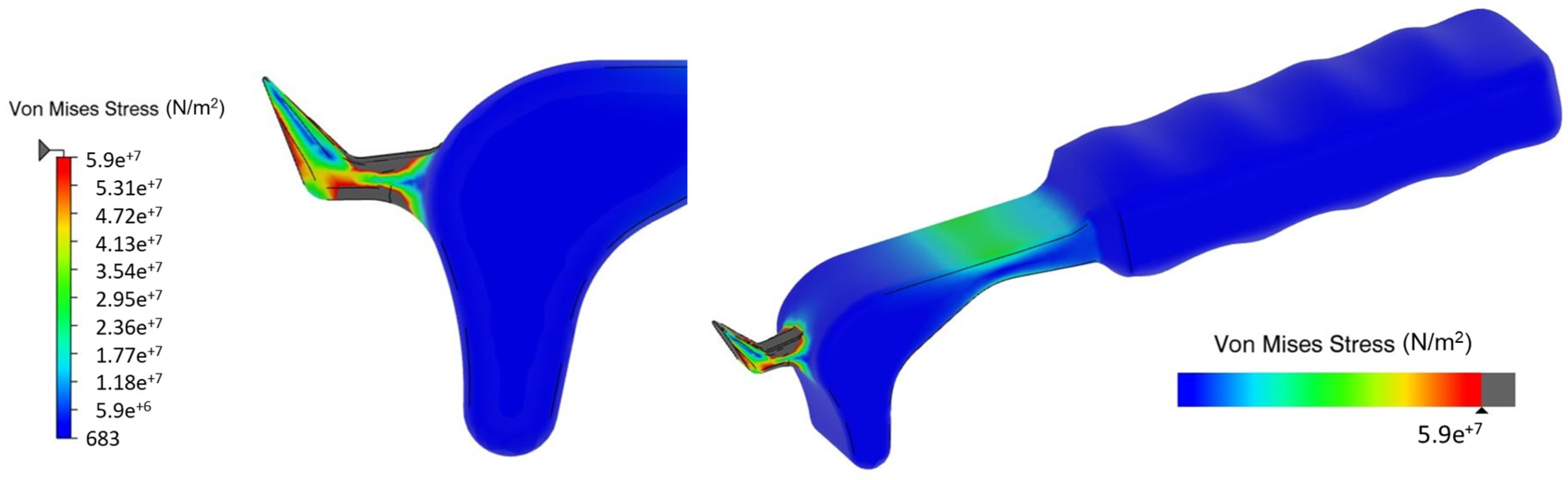
To overcome these limitations, the device is required to be improved in its design working on structural strength. An FEA simulation of the can opener shows that the part failure is related to a high stress concentration on the front hook. In particular,
Figure 4 shows that a force of 50 N (about 5 kg) applied at the handle causes a stress on the region that is over the threshold of the tensile strength (about 59 MPa) of the material.
3.3. Design Objectives and Constraints
Firstly, to define Product Data for design optimisation, objectives and constraints are analysed:
The part general shape should be kept to preserve the AD functionality. In particular, the can opener had been functionally optimised in lifter and fulcrum size and shape, so these elements should not be modified.
To improve structural behaviour, a material change is required at least for the stressed elements, which have to be made of metal. Mean values of mechanical properties of some of the strongest materials processed by FFF have been analysed and compared to a stainless steel obtained by powder bed fusion (PBF), as shown in
Table 1. Special filaments like Sabic Ultem
® PEI [
23] or PEEK [
24] can reach optimal strength, with the issue of very high costs.
Since the AD has to be provided free of charge, costs have to be minimised. Minimum metal material usage is fundamental, according to eventual technological constraints to reduce production cost. Moreover, the material saving leads to lower costs for required energy and machine time.
To create the redesign of a part to be produced by AM, aiming at improving part strength while reducing its mass, freeform TO has been chosen as the key step for product optimisation.
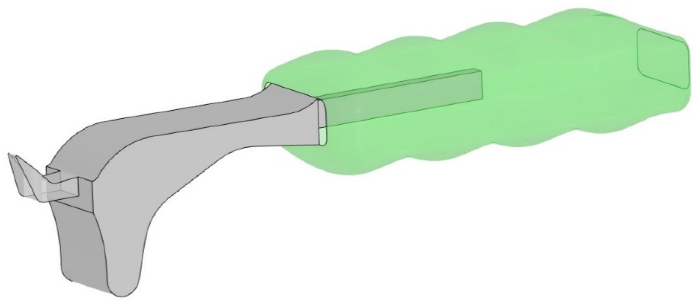
The redesign is based on splitting the AD in two parts, which are the already the optimised handle, made of PLA, and a structural head featuring a beam insert, made of 316L Stainless Steel (316L SS) (
Figure 5). The parts have to be additively manufactured, respectively, by FFF and PBF technologies, and then they can be coupled and glued.
3.4. Optimisation Approach and Tools
A general DfAM approach based on TO can be implemented using an integrated platform to perform design optimisation, since it could provide benefits speeding up the DfAM workflow due to data management and exchange minimisation [
13]. The platform allows integration of TO, product simulation, printing preparation and process simulation tools into the CAD environment [
17]. Moreover, it provides a specific feature to generate data that can be manipulated in order to perform the aforementioned trade-off study step. We selected the Dassault Systèmes 3DExperience platform.
Once objectives and constraints have been defined, a concept development phase based on optimisation computing, structural validation and process-related remarks is required. Subsequently, the trade-off study based on results of TO can be used to select the final concept model. Finally, detail modelling is required to obtain the optimised component and then physical prototyping can start.
4. Results
4.1. Model Setup
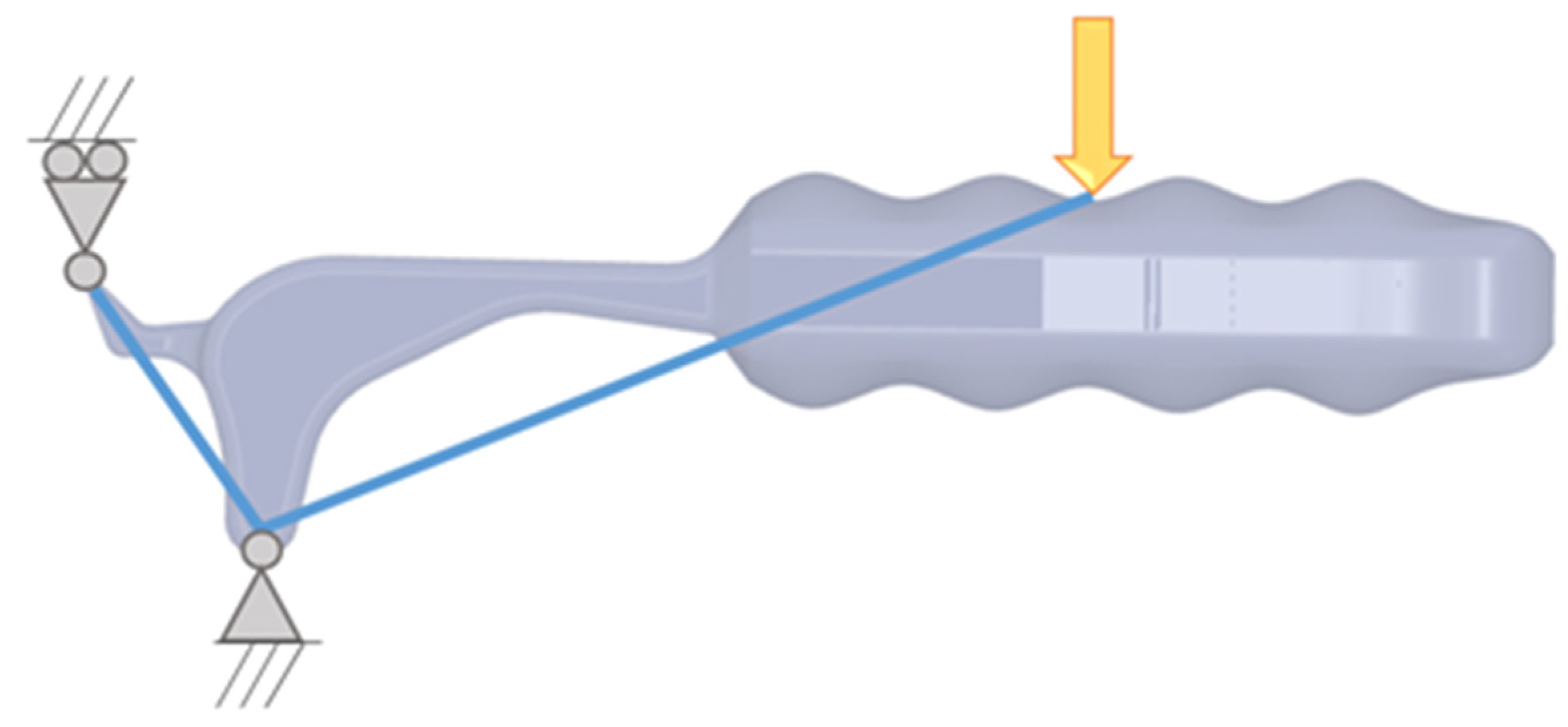
To simulate part behaviour during the can opening, the structural modelling consists of a load positioned at the centre of the handle with vertical direction (load condition), a hinge allowing rotation on the fulcrum and a fixed displacement restraint in the vertical direction on the top of the lifter (restraints), as shown in
Figure 6.
The Design Space for computation originates from the original can opener model: it should be as large as possible to avoid over-constraining the optimisation. Moreover, three functional elements are introduced as Non-Design Space volumes: the beam insert introduced to couple with the plastic handle and, according to the functional design constraints, the optimised lifter and fulcrum size and shape.
4.2. Topology Optimisation
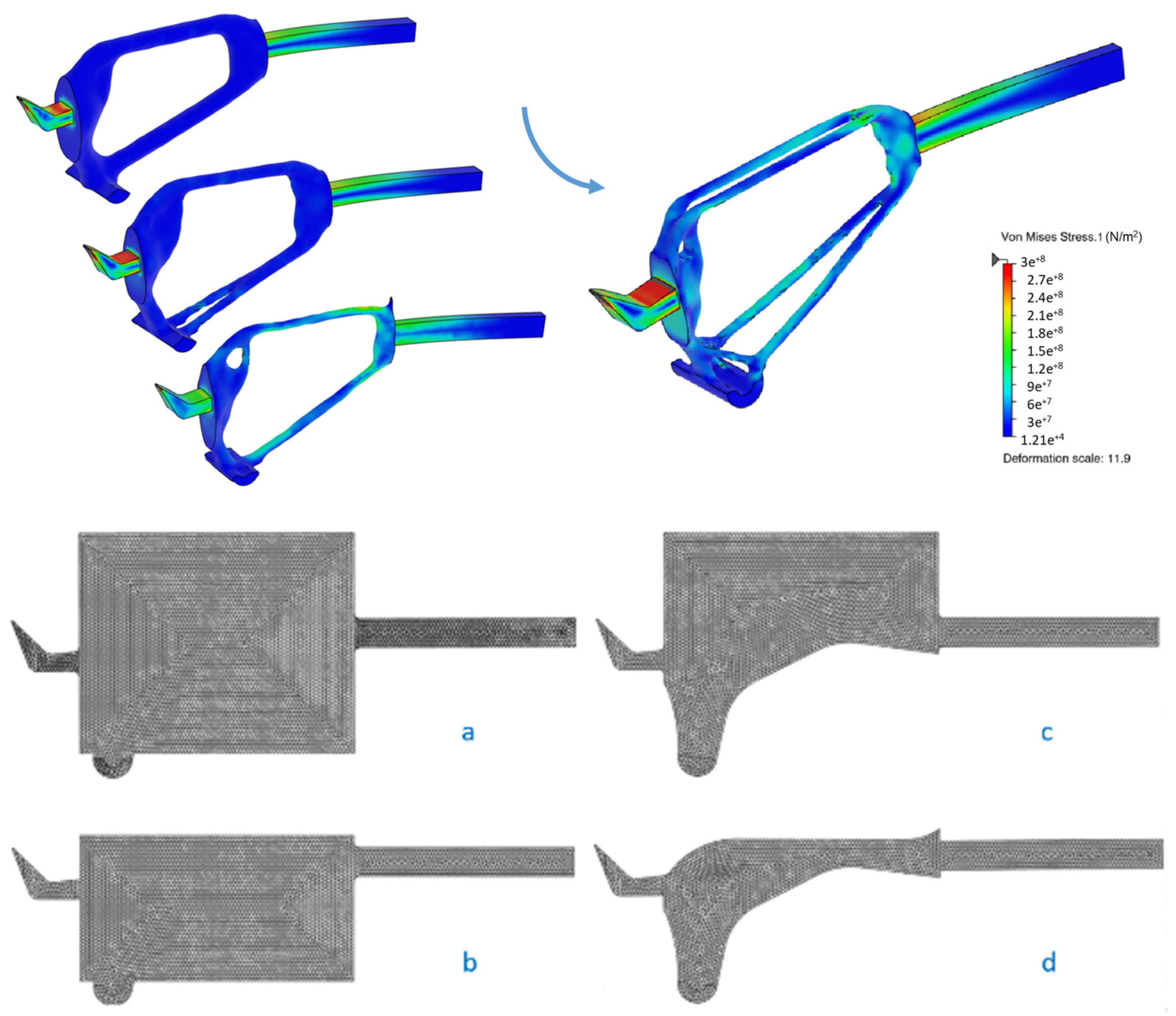
A computational algorithm is set up to maximise part stiffness for a fixed target mass. Firstly, sunder iterations between optimisation and structural validation lead to the establishment of target mass value, as depicted in
Figure 7 (top). First computations are based on a rough mesh in order to reduce computational cost whereas subsequent models are refined by creating a finer mesh in order to obtain more accurate results.
TO is run on four design spaces, ranging between the design space shape constrained by the original part profile and an enlarged design space in order to study the ideal shape from a structural point of view.
Figure 7 (bottom) shows firstly the enlarged design space (a), which corresponds to a volume that includes the original can opener model but is limited on three sides by the functional elements, which cannot be modified. Then, the top-limited design space (b) considers only the volume below the upper face of the original model while, conversely, the bottom-limited one (c) cannot exceed the can opener’s lower profile. Finally, the fully limited design space (d) cannot exceed the original part profile. The design space should bring to the result the best structural performance. It is fundamental to preserve the lower profile (i.e., the fulcrum), since it is given by the part envelope during the can opening. Conversely, for the upper shape, further constraints are not necessary, and, in this way, optimisation can be less constrained, so both results from design space (c) and (d) are feasible. TO setup is based on a target mass around 25 g, and a process-related constraint of minimum thickness for computed elements of 2.5 mm.
4.3. Concept Simulation
The results from TO have to be validated from a structural point of view. The use of an integrated platform allows one to obtain a finite element simulation directly on the optimisation output. A tool for automatic generation of a solid model starting from the computed shape is used for this purpose. Since a manual modelling for geometry interpretation is not required before having a structural validation, the exploration process of possible solutions is sped up.
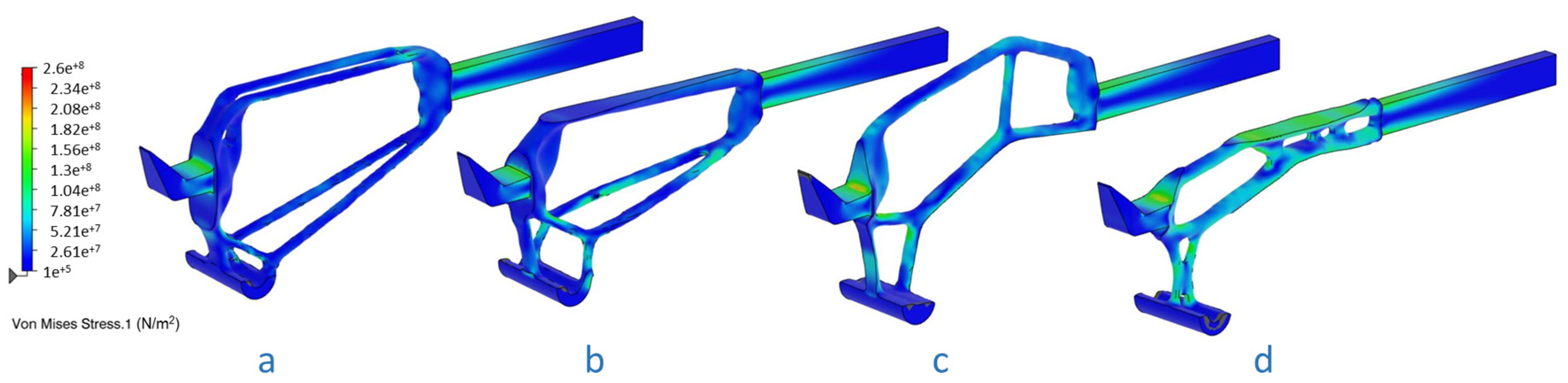
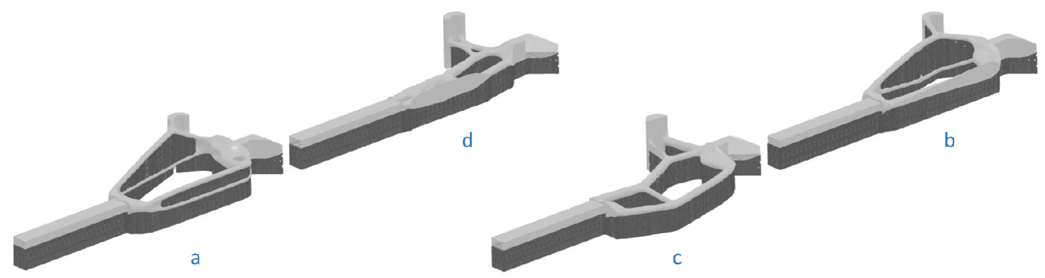
Figure 8 depicts results from the finite element analyses of concept models, respectively, from the enlarged (a), the top-limited (b), the bottom-limited (c) and the fully limited (d) design spaces. Maximum permissible stress is 260 MPa, calculated with a safety factor = 2 from the 316L SS tensile strength.
Concept models are validated since the stress of each one is below the maximum permissible. As expected, the unconstrained model (a) shows the best performance, while the fully limited one (d) shows the worst stiffness.
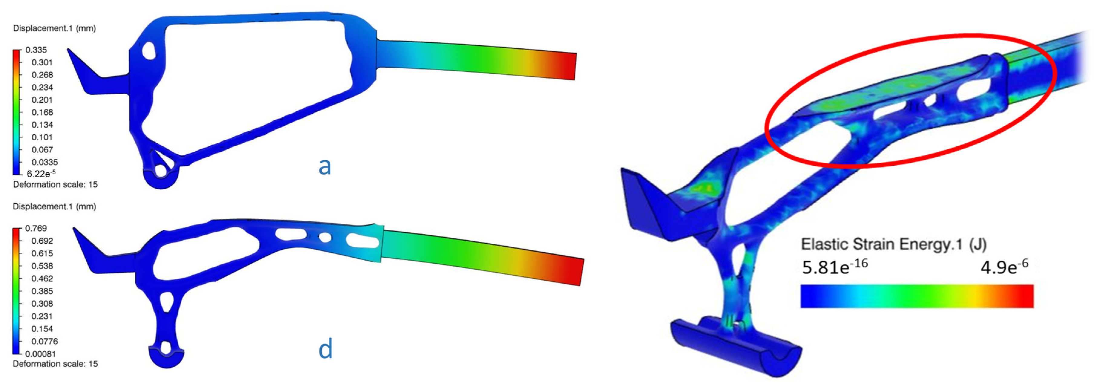
Figure 9 depicts part deformations and shows that concept (a) has a maximum displacement less than half of concept (d).
Figure 9 depicts in particular a high level of strain energy on its upper surface—a sign that the shape constraint in that region badly affects the part behaviour.
4.4. Concept Industrialisation
An industrialisation study on concept shapes is necessary to evaluate the amount of supports required to produce the parts, since their introduction leads to higher material usage (as well as energy and machine time) and increases AD costs. To do that, as shown in
Figure 10, printing preparation of models has been performed, including proper part orientation and generation of wire type perforated supports. The model’s orientation is selected for both component’s strength maximisation (considering material anisotropy) and support material minimisation (considering process costs).
The volume of each part, including its supports, has been calculated to quantitatively evaluate variation in usage of material, energy and machine time, under the hypothesis of the linear link between build time and material to be processed.
4.5. Trade-Off Study
Concept models have to be evaluated on the basis of part mass, its structural features, but also on a technological point of view. Many actual design efforts aim at combining both structural and economical aspects [
25]. In this way, a first analysis includes the design performance (structural aspect) and a second one, the industrialisation (economical aspect).
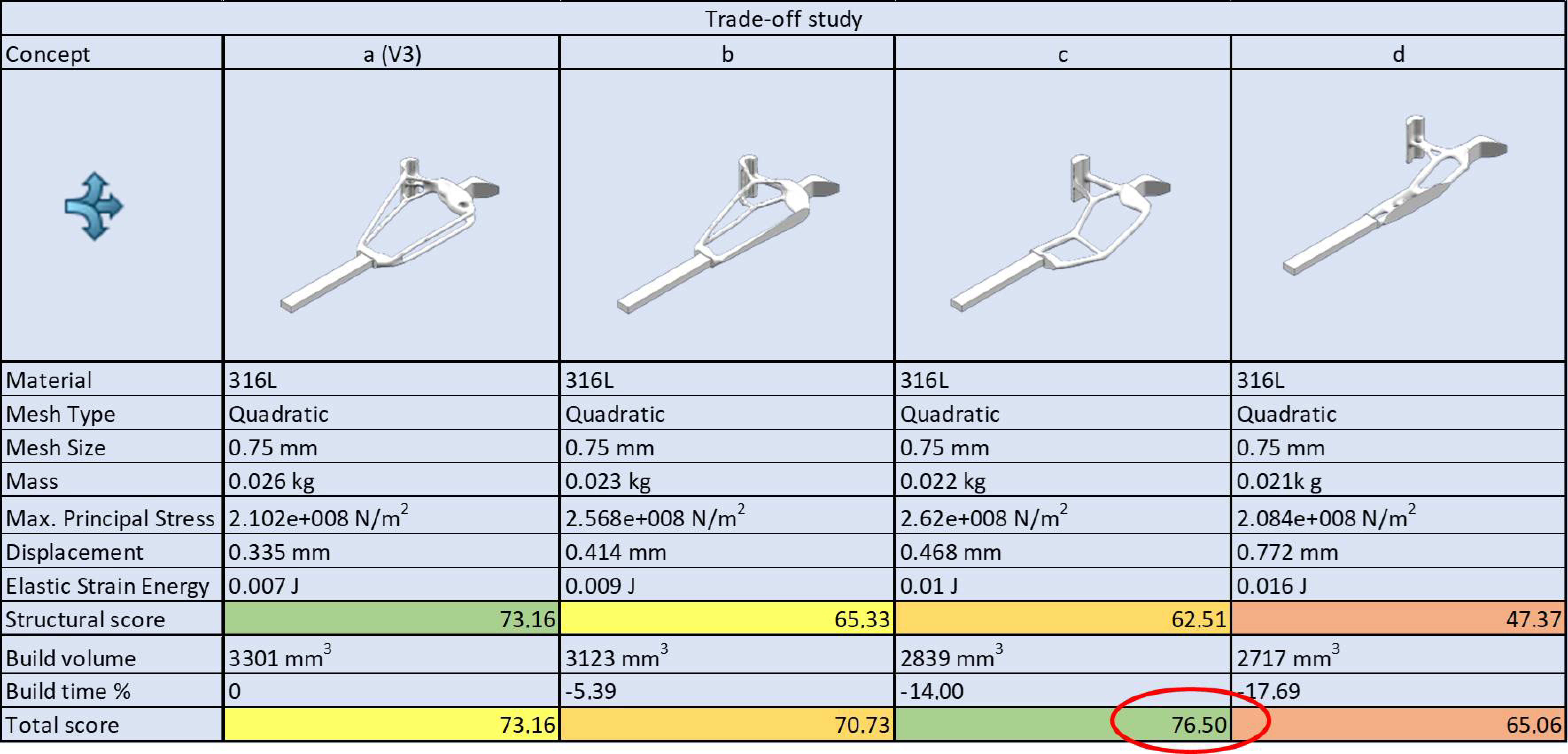
Figure 11 summarises the performed trade-off study based on both the product and process elements, considering the four concepts (a in its third refinement version (V3), b, c, and d).
The first analysis is based on KPIs such as mass, part compliance and elastic strain energy minimisations; in addition, a structural score has been calculated. The result, as expected, is that concept (a) shows the best topology and the best performance: while not the lightest in mass, it has the best stress state, stiffness and the lowest strain energy. Subsequently, the volume of each part, including its supports, has been considered to quantitatively evaluate changes in material, energy and machine time usage. Then, the calculated score has been added to the first to obtain a total score for concept selection, taking into account even production costs. Results from the first analysis change, for example concept (a), which showed the best structural score, is the one with the maximum material usage. In particular, concept (c), despite having quite lower features with regard to stiffness, stress state and strain energy, shows lower mass (just higher than concept (d)) and strongly requires less support material, so the estimated build time is reduced by 14%. Considering both analyses, the best total score is assigned to (c) and thus it has been selected for the final design.
4.6. Final Design
Once the final concept selection is performed, redesign operations are required. Usually, the application of the general DfAM workflow using specific stand-alone tools requires many redesigns. Conversely, through a CAD platform it can be possible to carry out the whole design solutions exploration without making geometry interpretations and thus limiting the redesign step to the selected concept solution. This can lead to high effectiveness of the method and reduction in product development time.
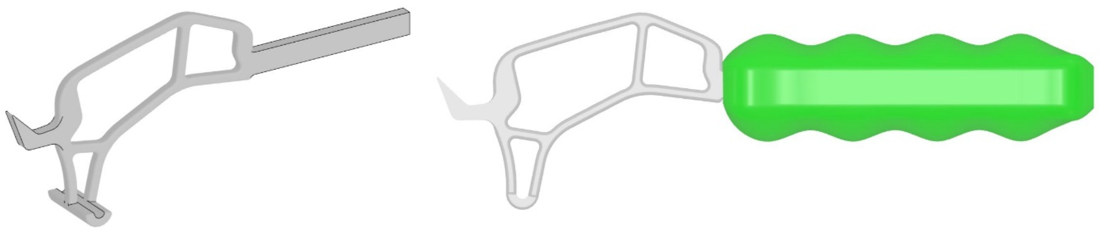
Figure 12 depicts the final design for the topology optimised structural head and the model of the AD with the handle assembled.
4.7. Production and Testing
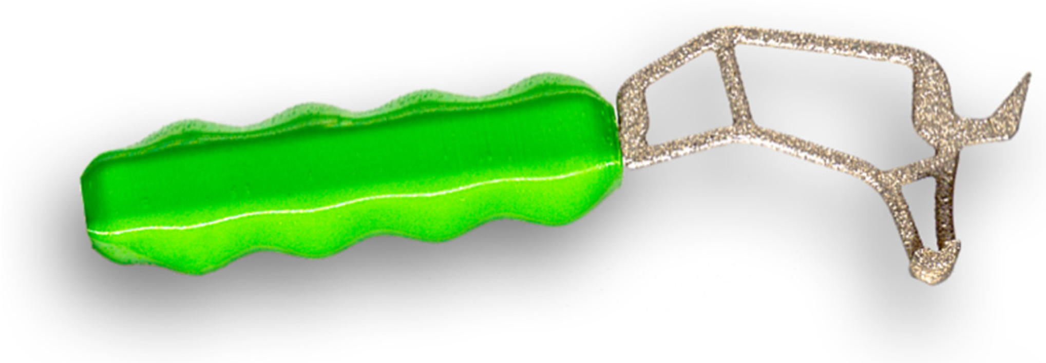
Concerning the production phase, the process setup of the structural metal head to be built by PBF defined in the industrialisation study is achieved. Conversely, the plastic handle is built by a rapid prototyping standard FFF process. As previously mentioned, the head is made of 316L SS while the handle is made of PLA. Subsequently, the post-processing phase is performed on both components and they are glued.
Figure 13 shows the printed and assembled optimised product.
Finally, a physical test for final validation of the optimised product is required. Subsistence of part functionality is verified, and structural strength and wear resistance specifications are respected.
Figure 14 shows the AD usage operations.
5. Conclusions
This paper presents a systematic workflow for the redesign of a part or component and its additive manufacturing production, after being topologically optimised. Starting from a traditional manufacturing technology, the workflow leads to technology change and material replacement.
Today, AM is used in all the fields requiring single-batch production and maximum customisation, thanks to its inner production potentials. Moreover, the use of TO leads to lightweight structures, even if it generates more than one design variants with similar performance, so design selection criteria are urged, such as the one presented here.
The main pros of the workflow are:
It can be integrated into other existing methods for product and process optimisation.
It explores all the solutions developable thanks to AM but, at the same time, it offers their structured evaluation process.
KPIs can be integrated allowing one to respond to specific design needs.
The method requires dedicated tools and is favoured by an integrated platform because it addresses the entire workflow, but it can also be implemented with different and stand-alone tools.
The use of an integrated platform leads to shortened times, reduced validation/optimisation times because it is managed systematically.
The method is independent from the geometry to be redesigned, so it can fit with different fields of applications; in this paper, it is applied to the redesign of a medical AD but can easily be extended to other sectors.
Regarding the specific case study, the results show:
Increased performance and achievement of the functional goals.
On the one hand, the new technology replaces the previous process but, on the other hand, it integrates with it by splitting the component into two parts (the method acts only on the most critical one).
The redesign preserves and indeed improves the primary functionality of the AD (structural aspect) and responds to further needs, e.g., durability over time.
As a main con, the construction costs are high and not convenient for large-scale production, even if the workflow allows for cost minimisation thanks to TO and the cost itself is partly compensated by the part durability, since the original part requires frequent replacements.
Author Contributions
Conceptualisation, E.D., F.G., F.P. and F.L.; methodology, E.D., F.P. and F.G.; validation, E.D., F.G. and F.P.; writing—original draft preparation, E.D. and F.G.; writing—review and editing, E.D., F.G. and F.P.; supervision, F.L. All authors have read and agreed to the published version of the manuscript.
Funding
This research and the article processing charge ere funded by University of Modena and Reggio Emilia—UNIMORE (Italy), Fondo Ateneo Ricerca Progetti FAR Dipartimentale 2019-PROT. 192218 del 20/09/19-CdA 23/07/19-Bando interno.
Acknowledgments
The authors gratefully acknowledge Elena Bassoli and Riccardo Groppo for their valuable support, and Francesco Prochilo for the photographs of
Figure 13 and
Figure 14.
Conflicts of Interest
The authors declare no conflict of interest.
References
- Gao, W.; Zhang, Y.; Ramanujan, D.; Ramani, K.; Chen, Y.; Williams, C.B.; Wang, C.C.L.; Shin, Y.C.; Zhang, S.; Zavattieri, P.D. The status, challenges, and future of additive manufacturing in engineering. CAD Comput. Aided Des. 2015, 69, 65–89. [Google Scholar] [CrossRef]
- Thompson, M.K.; Moroni, G.; Vaneker, T.; Fadel, G.; Campbell, R.I.; Gibson, I.; Bernard, A.; Schulz, J.; Graf, P.; Ahuja, B.; et al. Design for Additive Manufacturing: Trends, opportunities, considerations, and constraints. CIRP Ann. Manuf. Technol. 2016, 65, 737–760. [Google Scholar] [CrossRef]
- du Plessis, A.; Broeckhoven, C.; Yadroitsava, I.; Yadroitsev, I.; Hands, C.H.; Kunju, R.; Bhate, D. Beautiful and functional: A review of biomimetic design in additive manufacturing. Addit. Manuf. 2019, 27, 408–427. [Google Scholar] [CrossRef]
- Chen, D.; Heyer, S.; Ibbotson, S.; Salonitis, K.; Steingrímsson, J.G.; Thiede, S. Direct digital manufacturing: Definition, evolution, and sustainability implications. J. Clean. Prod. 2015, 107, 615–625. [Google Scholar] [CrossRef]
- Desai, K. Factors influencing success of metal to plastic conversion programs for under-hood applications. SAE Tech. Pap. 1996, 960149. [Google Scholar] [CrossRef]
- Marur, S. Plastics Application Technology for Lightweight Automobiles; SAE International: Warrendale, PA, USA, 2013; ISBN 978-0-7680-7640-0. [Google Scholar]
- Ahangar, P.; Cooke, M.E.; Weber, M.H.; Rosenzweig, D.H. Current biomedical applications of 3D printing and additive manufacturing. Appl. Sci. 2019, 9, 1713. [Google Scholar] [CrossRef]
- Gibson, I.; Rosen, D.; Stucker, B. Additive Manufacturing Technologies: 3D Printing, Rapid Prototyping, and Direct Digital Manufacturing; Springer: New York, NY, USA, 2015. [Google Scholar] [CrossRef]
- Tack, P.; Victor, J.; Gemmel, P.; Annemans, L. 3D-printing techniques in a medical setting: A systematic literature review. Biomed. Eng. 2016, 15, 115. [Google Scholar] [CrossRef] [PubMed]
- Lunsford, C.; Grindle, G.; Salatin, B.; Dicianno, B.E. Innovations with 3-dimensional printing in physical medicine and rehabilitation: A review of the literature. PM&R 2016, 8, 1201–1212. [Google Scholar] [CrossRef]
- Ganesan, B.; Al-Jumaily, A.; Luximon, A. 3D printing technology applications in occupational therapy. Phys. Med. Rehabil. Int. 2016, 3, 1085–1089. [Google Scholar]
- Gherardini, F.; Mascia, M.T.; Bettelli, V.; Leali, F. A co-design method for the additive manufacturing of customised assistive devices for hand pathologies. J. Integr. Des. Process Sci. 2019, 22, 21–37. [Google Scholar] [CrossRef]
- Dalpadulo, E.; Pini, F.; Leali, F. Assessment of design for additive manufacturing based on CAD platforms. Lect. Notes Mech. Eng. 2020, 970–981. [Google Scholar] [CrossRef]
- Plocher, J.; Panesar, A. Review on design and structural optimisation in additive manufacturing: Towards next-generation lightweight structures. Mater. Des. 2019, 183, 108164. [Google Scholar] [CrossRef]
- Laverne, F.; Segonds, F.; Anwer, N.; Le Coq, M. DfAM in the design process: A proposal of classification to foster early design stages. In Proceedings of the Conference 2014 Croatie, Sibenik, Croatie, 3–4 July 2014; pp. 1–12. [Google Scholar]
- Kumke, M.; Watschke, H.; Vietor, T. A new methodological framework for design for additive manufacturing. Virtual Phys. Prototyp. 2016, 11, 3–19. [Google Scholar] [CrossRef]
- Dalpadulo, E.; Pini, F.; Leali, F. Integrated CAD platform approach for design for additive manufacturing of high performance components. Int. J. Interact. Des. Manuf. 2020, 14, 899–909. [Google Scholar] [CrossRef]
- Liu, J.; Gaynor, A.T.; Chen, S.; Kang, Z.; Suresh, K.; Takezawa, A.; Li, L.; Kato, J.; Tang, J.; Wang, C.C.L.; et al. Current and future trends in topology optimization for additive manufacturing. Struct. Multidiscip. Optim. 2018, 57, 2457–2483. [Google Scholar] [CrossRef]
- Wiberg, A.; Persson, J.; Ölvander, J. Design for additive manufacturing—A review of available design methods and software. Rapid Prototyp. J. 2019. [Google Scholar] [CrossRef]
- Lindemann, C.; Reiher, T.; Jahnke, U.; Koch, R. Towards a sustainable and economic selection of part candidates for additive manufacturing. Rapid Prototyp. J. 2015, 21, 216–222. [Google Scholar] [CrossRef]
- Dalpadulo, E.; Pini, F.; Leali, F. Systematic integration of topology optimization techniques in design for additive manufacturing methodologies applied to automotive settings. In Proceedings of the International Mechanical Engineering Congress and Exposition (IMECE)—2020, Virtual Conference, Portland, OR, USA, 16–19 November 2020. [Google Scholar]
- Gherardini, F.; Petruccioli, A.; Dalpadulo, E.; Bettelli, V.; Mascia, M.T.; Leali, F. A methodological approach for the design of inclusive assistive devices by integrating co-design and additive manufacturing technologies. In Advances in Intelligent Systems and Computing, Proceedings of the IHSI 2020, Modena, Italy, 19–21 February 2020; Springer: New York, NY, USA, 2020; Volume 1131, pp. 816–822. [Google Scholar] [CrossRef]
- Padovano, E.; Galfione, M.; Concialdi, P.; Lucco, G.; Badini, C. Mechanical and thermal behavior of ultem® 9085 fabricated by fused-deposition modeling. Appl. Sci. 2020, 10, 3170. [Google Scholar] [CrossRef]
- Rinaldi, M.; Ghidini, T.; Cecchini, F.; Brandao, A.; Nanni, F. Additive layer manufacturing of poly (ether ether ketone) via FDM. Compos. Part B Eng. 2018, 145, 162–172. [Google Scholar] [CrossRef]
- Cicconi, P.; Castorani, V.; Germani, M.; Mandolini, M.; Vita, A. A multi-objective sequential method for manufacturing cost and structural optimization of modular steel towers. Eng. Comput. 2020, 36, 475–497. [Google Scholar] [CrossRef]
Figure 1.
General design for additive manufacturing workflow.
Figure 1.
General design for additive manufacturing workflow.
Figure 2.
Systematic concept selection-based approach for product optimisation.
Figure 2.
Systematic concept selection-based approach for product optimisation.
Figure 3.
Workflow for the co-design of assistive devices, involving patients (P), occupational therapists (OT) and design engineers (DE). The dashed-line box highlights the iterative phases in which topology optimisation (TO), trade-off study and redesign may occur.
Figure 3.
Workflow for the co-design of assistive devices, involving patients (P), occupational therapists (OT) and design engineers (DE). The dashed-line box highlights the iterative phases in which topology optimisation (TO), trade-off study and redesign may occur.
Figure 4.
Structural analysis performed on the original assistive device (AD).
Figure 4.
Structural analysis performed on the original assistive device (AD).
Figure 5.
Layout of the product to be optimised.
Figure 5.
Layout of the product to be optimised.
Figure 6.
Structural model for shape computation and simulation.
Figure 6.
Structural model for shape computation and simulation.
Figure 7.
(Top): Topology optimisation refinement of the concept (a) and (bottom): a comparison of the enlarged (a), the top-limited (b), the bottom-limited (c) and the fully limited (d) design spaces.
Figure 7.
(Top): Topology optimisation refinement of the concept (a) and (bottom): a comparison of the enlarged (a), the top-limited (b), the bottom-limited (c) and the fully limited (d) design spaces.
Figure 8.
Concepts generated from TO results starting from the enlarged (a), the top-limited (b), the bottom-limited (c) and the fully limited (d) design spaces.
Figure 8.
Concepts generated from TO results starting from the enlarged (a), the top-limited (b), the bottom-limited (c) and the fully limited (d) design spaces.
Figure 9.
Deformation of concepts (a) and (d) and elastic strain energy of concept (d).
Figure 9.
Deformation of concepts (a) and (d) and elastic strain energy of concept (d).
Figure 10.
Industrialisation study of concepts (a–d).
Figure 10.
Industrialisation study of concepts (a–d).
Figure 11.
Key performance indicators (KPIs) matrix involved in the trade-off study step: the four concepts (a–d) are compared in the columns.
Figure 11.
Key performance indicators (KPIs) matrix involved in the trade-off study step: the four concepts (a–d) are compared in the columns.
Figure 12.
Final models of structural head and assistive device.
Figure 12.
Final models of structural head and assistive device.
Figure 13.
Three-dimensional printed optimised assistive device.
Figure 13.
Three-dimensional printed optimised assistive device.
Figure 14.
Optimised assistive device testing.
Figure 14.
Optimised assistive device testing.
Table 1.
Material comparison for additive manufacturing process: fused filament fabrication (FFF) and powder bed fusion (PBF).
Table 1.
Material comparison for additive manufacturing process: fused filament fabrication (FFF) and powder bed fusion (PBF).
| Material | PLA (FFF) | PC (FFF) | Special (FFF) | 316L (PBF) |
|---|
| Density (kg/m3) | 1.24 | 1.2 | 1.32 | 7.91 |
| Young’s modulus (GPa) | 2.15 | 2.25 | 3.5 | 180 |
| Ultimate tensile strength (MPa) | 59 | 68 | 100 | 530 |
| Specific Cost (EUR/kg) | 25 | 50 | 500 | 150 |
| Publisher’s Note: MDPI stays neutral with regard to jurisdictional claims in published maps and institutional affiliations. |
© 2020 by the authors. Licensee MDPI, Basel, Switzerland. This article is an open access article distributed under the terms and conditions of the Creative Commons Attribution (CC BY) license (http://creativecommons.org/licenses/by/4.0/).


