Article

Numerical Evaluation of the Transient Performance of Rock-Pile Seasonal Thermal Energy Storage Systems Coupled with Exhaust Heat Recovery

by
Leyla Amiri
1,2,
Marco Antonio Rodrigues de Brito
3,
Seyed Ali Ghoreishi-Madiseh
3,*,
Navid Bahrani
2,
Ferri P. Hassani
1 and
Agus P. Sasmito
1,*
1
Department of Mining and Materials Engineering, McGill University, Adams Building, Montreal, QC H3A 2A7, Canada
2
Department of Civil and Resource Engineering, Dalhousie University, Sexton Campus, Halifax, NS B3H 4R2, Canada
3
Norman B. Keevil Institute of Mining Engineering, University of British Columbia, Vancouver, BC V6T 1Z4, Canada
*
Authors to whom correspondence should be addressed.
Appl. Sci. 2020, 10(21), 7771; https://doi.org/10.3390/app10217771
Submission received: 6 October 2020 / Revised: 27 October 2020 / Accepted: 31 October 2020 / Published: 3 November 2020
(This article belongs to the Special Issue Thermal Energy Storage Systems)

Abstract

:
This study seeks to investigate the concept of using large waste rocks from mining operations as waste-heat thermal energy storage for remote arctic communities, both commercial and residential. It holds its novelty in analyzing such systems with an experimentally validated transient three-dimensional computational fluid dynamics and heat transfer model that accounts for interphase energy balance using a local thermal non-equilibrium approach. The system performance is evaluated for a wide range of distinct parameters, such as porosity between 0.2 and 0.5, fluid velocity from 0.01 to 0.07 m/s, and the aspect ratio of the bed between 1 and 1.35. It is demonstrated that the mass flow rate of the heat transfer fluid does not expressively impact the total energy storage capacity of the rock mass, but it does significantly affect the charge/discharge times. Finally, it is shown that porosity has the greatest impact on both fluid flow and heat transfer. The evaluations show that about 540 GJ can be stored on the bed with a porosity of 0.2, and about 350 GJ on the one with 0.35, while the intermediate porosity leads to a total of 450 GJ. Additionally, thermal capacity is deemed to be the most important thermophysical factor in thermal energy storage performance.

1. Introduction

Increasing population and economic growth in the past years has significantly amplified fossil fuel dependency and its impact on the environment [1]. This has caused industries to search for alternatives to fossil fuel and more environmentally-friendly solutions for energy generation. With the increase in usage of renewable and alternative technologies, energy storage has gained great importance [2,3]. Thermal energy storage (TES) allows for energy to be stored in the form of heat in times of low or null demand, and used later whenever demand rises [2]. Such technologies aid in the reduction of both carbon footprints and energy costs from small (residential) to big (industrial) scales, being even deemed vital in some applications [4,5]. Such technologies are mostly used in solar energy applications, mainly concentrated solar power plants (CSP) [3,6,7,8] and solar district heating [9,10,11,12,13], but waste-heat storage systems can also take great advantage of their use [14,15,16,17]. Among the three main types of TES systems: chemical heat storage (based on thermochemical reactions); latent heat storage (which employs phase change materials); and sensible heat storage (simply based on temperature increase/decrease of the storage media) [2], the latter is currently the cheapest and easiest one to implement [5]. It has been stated that a sensible heat storage costs up to 15 CAD/kWh, while a latent heat storage needs relatively higher costs, up to 150 CAD/kWh, depending on many factors such as the size, the material, and the applied technology [18]. For that reason, it is the most promising one for immediate use in large/industrial scales [19]. That happens as it generally implements inexpensive resources as fragmented rock and air [20], and it often dispenses the need of intermediate heat exchangers [16].
It has been shown previously that rock-bed storage systems frequently are more cost-effective than similar water-based systems for heating [11]. Still, other advantages of such systems can be highlighted. They are more environmentally friendly than their counterparts, as they use naturally occurring storage media, they can usually withstand very high temperatures, and they also have a high heat transfer coefficient between phases when in use, but low conductivity of heat when air flow is not present [12]. Despite being used mostly for solar applications, due to its flexibility, packed rock-bed TES can be employed in a wide range of energy-intensive industries. A good example is the development of the application for mine sites, where there is an opportunity to use fragmented rock packed in beds as a sensible energy storage. In these storages, air is used as the heat transfer fluid (HTF) and fragmented rocks are used as the storage media, which has been shown as a favorable approach for TES systems [21,22,23,24,25].
In order to fully understand the performance of TES systems, several parameters ought to be analyzed, which are hard to attain by analytical equations. Hence, computational simulations are usually a good method to investigate and enhance such systems, by improving the many factors affecting its operation. For that reason, several works in literature have taken the task to develop such computational models. Some of these that can be highlighted focused on the heat and mass transfer phenomena occurring within packed beds used as thermal energy storage [26]. Abdel-Salam et al. established a cylindrical coordinate-based 1D numerical model, through which it was revealed that the increase of bed length improves storage capacity while not affecting the rate of charge [4]. By implementing the finite difference method in models with distinct number of sections, Arias et al. investigated the possibility of using them to represent the stratification phenomena seen in experimental tests [27]. Hänchen et al. elaborated a one-dimensional numerical model, followed by comparison validation against experimental data from small-scale testing [28]. Looking to investigate the effect of construction parameters on heat storages for industrial processes, Zanganeh et al. developed a quasi-one-dimensional transient model to study two-phase heat transfer on packed beds [16]. Barton developed a one-dimensional model for airflow within a porous rock bed medium, and used it to study the effect of different charging and discharging flow direction schedules [29]. Kuravi et al. studied a large-sized packed bed (created with bricks) circulating air as an HTF with experiments and a 1D energy model, and confirmed the viability of its fluid flow and heat transfer for solar applications [30]. Finally, Cascetta et al. worked on experimental and numerical tests, focusing on their comparison, and achieved satisfactory results on simulations that had input temperatures from experiments [31].
When it comes to design and operation of porous media storage systems, two important parameters ought to be highlighted: the rate of heat transfer between fluid and solid domains, and the power necessary to run the heat transfer fluid through the system. The former determines operating cost, while the latter is directly related to storage capacity and rate. Besides, other case-specific factors can directly impact the outcome of the system. Hence, it is crucial to fully comprehend the porous structure of the rock bed domains and how important they are for the design of heat storage systems. Some studies have focused on evaluating influential parameters. Optimizing the heat transfer rate between the fluid and solid domains has been demonstrated to be a key factor to achieve a good performance on TES systems [32]. Mertens et al. [8] and Rodat et al. [33] investigated, in detail, both numerically and experimentally, the performance of sand and rock beds, which allowed for the impact of several design and operating conditions, as temperature and HTF velocity, to be evaluated on thermal energy storage performance. Air mass flow has been shown to enhance interphase heat transfer rates, decreasing charging time [4], while some have suggested that air density would not directly affect said heat transfer [29]. It has also been stated that volumetric heat capacity would play a major role on overall system performance [28]. Regarding insulation, a thickness of about 16–20 cm was found to be enough to retain low energy losses for intermediate temperatures [16]. Studies have also shown that for short-term (diurnal) cycles, a 95% overall thermal efficiency is achievable [7]. Another study was performed to evaluate rock suitability for use on TES, regarding chemical, mechanical, and thermophysical properties, and it found that some rocks which are not thermally stable (like foliated rocks) could be unsuitable. Finally, it has been stated that there is no absolute optimum design to a rock-bed TES system, meaning every unit needs to be planned and directed towards the requirements for cost and performance of the specific application.
It is important to note that the majority of experimental data available in literature focuses on lab-scale models. Not many studies exist in literature investigating the heat transfer phenomena on large-scale rock-bed TES as the ones with potential for implementation in mining applications. Only recently has thought been put into uses of rock beds, such as cooling/heating of intake air in underground mining sites and block-caved mine ventilation systems [21,24]. It is very important to investigate pressure drop on those systems, as significant additional fan power is required to pump the air through the bed [34,35], which leads to meaningfully high costs that could affect the viability of the system.
Even though several studies have modelled heat transfer and fluid flow in a packed bed of rocks, most of them present restrictions, including a dimensional reduction to a 2D, 1D, or quasi-1D model, neglecting heat transfer in at least one of the three special dimensions. Others have employed simplifications from interphase energy balance (obtained by the local thermal non-equilibrium method (LTNE)) to a less realistic local thermal equilibrium (LTE). A few even neglect pressure differentials. This study focuses on a TES system being charged by a stream of hot air, the product of the exhaust from a local power plant. The novel approach proposed here is the use of large rocks (possibly waste rock from mining operations) as storage medium while using streams of hot gases (such as those from exhaust) as the heat source of the thermal energy storage system. The latter contains energy commonly discarded to the ambient air at establishments employing diesel-based power plants, such as the ones present on remote communities in Canada [15,17]. Not only commercial (as remote mining operations), these establishments that spread over the arctic regions in Canada commonly house first nation groups. In fact, it is estimated that about 300 remote communities of this kind exist in Canada alone [36]. It is important to note that this implementation of TES in large-scale rock beds compares to previous work done on natural heat exchange areas for mining applications [24,25], simply based on particle size of storage media and heat transfer mechanisms involved, differing completely in heat source and grade, application, charging/discharging rates, heat transfer rates, and nature of the fluid flow within the porous media. Therefore, this research holds its novelty on the investigation of the effects of several physical characteristics of a rock-bed TES charged through waste heat for space heating applications. Such a task is achieved employing a three-dimensional, transient model, based on the LTNE approach, by which heat transfer and fluid flow within the packed bed thermal storage system are studied through the use of computational fluid dynamics (CFD) models. The impact of several parameters on the performance of the large-sized, rock-bed waste-heat storage for remote communities is evaluated for several distinct scenarios, while focusing on the simultaneous impact of these with changes in system dimensions, i.e., aspect ratios (AR), which to the best knowledge of the authors, has not been performed before.

2. Model Description

The thermal storage system proposed here is based on a conical geometry with a truncated top. This format is selected due to the facilitation it offers for construction, since it can be easily achieved by stacking the chosen rock with trucks, complying to a determined angle of repose. Thus, this system has been referred to as a rock-pile TES [15], and is represented in Figure 1. Note that the directions of the flow and fluid inlet are inverted for charging (top to bottom) and discharging (bottom to top), to take advantage of the stratification of temperature within the HTF, as previously pointed out in literature [27].
As fluid flow develops within the rock bed, several heat transfer mechanisms will be present. To fully understand the operation of the system proposed, it is crucial to be attentive to the existing heat transfer mechanisms taking place. These are indicated in Figure 2. One of the main advantages of the technology presented is the fact that elevated heat transfer rates are achievable during operation due to the large total interphase heat transfer area. While in non-operating periods, with the absence of flow, the heat conduction and, consequently, dispersion and heat losses can be maintained at lower levels than other similar TES technologies. It is worth noting that, here, the solid phase is assumed to have constant thermophysical properties along the bed.
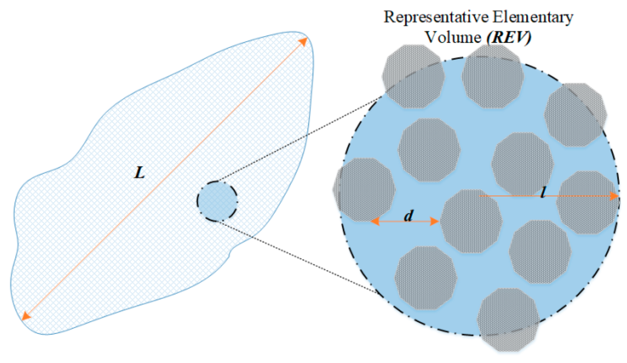
In order to analyze the rock-bed TES, a volume-averaged model (VAM) was developed. Using this model, it is possible to evaluate the mass and heat transfer phenomena within the bed, while requiring lower computational power relative to other methods. This is a consequence of it using macroscale flow characteristics in the porous media to evaluate the system’s outcomes. The viscous and inertial resistance coefficients needed for such a VAM model are obtained from empirical equations. Figure 3 depicts a representative elementary volume (REV), a typical unit used in the volume-averaged analysis. It is important to note that it is only suitable to use VAM for systems with l 5 d and l L [37,38]; in which d is the average diameter of the pore, and L and l are, respectively, the representative size of the flow domain and the REV.
Using ANSYS Fluent 17.2, the 3D computational model was created, meshed, and finally simulated. To solve the governing equations, the semi-implicit method for pressure-linked equation (SIMPLE) was implemented. Basically, two different methods can be used to solve the equation for conservation of energy in a porous media: a local thermal equilibrium (LTE) approach, and a local thermal non-equilibrium (LTNE) approach. When the thermal properties of the solid and the fluid are not comparable and the flow conditions through the system are highly transient, the latter model should be used. In said method, since the variation of the local rate of temperature for fluid and solid are different, two separate energy equations are solved. Hence, the heat transfer phenomena for both fluid and solid phases can be examined in the proposed thermal energy storage system. Accordingly, the following mass, momentum, and energy conservation equations (respectively) are then solved by the finite-volume analysis under LTNE conditions.
· u = 0
ρ ( u · u ) = p + · ( μ [ ( u + u T ) ] ) + ρ g α μ u β ρ u 2
( ε ρ c p T ) f t + · ( ρ c p u T ) f = · ( ε k T ) f + h f s A f s ( T s T f )
( ( 1 ε ) ρ c p T ) s t = · ( ( 1 ε ) k T ) s + h f s A f s ( T f T s )
where α is the viscous resistance coefficient and β is the inertial one, as given by Equations (5) and (6), respectively. Note that α represents the inverse of the permeability of the medium (K). Distinct porous bodies with increasing porosities ( ε ) from 0.2 to 0.5 and a particle size ( d ) were used in this study. To find values for α and β , the commonly employed Ergun correlation [39] is used. It is important that numerical and experimental studies be performed to obtain such values. Only then should Ergun correlation be assessed for each bed, and its validity confirmed.
α =   150 × ( 1 ε ) 2 d 2   × ε 3
β =   1.75 × ( 1 ε ) d × ε 3
Thus, having in mind its TES performance, a three-dimensional VAM is suggested to evaluate the main outcomes of the system, such as pressure drop/fan power requirements, total energy storage, charging rate, and temperature profiles of the bed, as a function of thermodynamic and physical parameters for different geometries (i.e., aspect ratios).

2.1. Heat Transfer Coefficient (HTC) in the Rock Bed

As previously mentioned, regarding the thermal energy storage systems, it is crucial to determine the convective heat transfer coefficient (HTC) between solid and fluid. Hence, it is fundamental to assume appropriate correlations to appropriately estimate the performance of such systems. Here, the correlations used are as given by Bejan [38], which are presented in Equations (7)–(9).
h f s = 6 h ( 1 ε ) / d p
1 h = d p N u f s k f + d p 10 k s
N u f s = 0.255 ε P r 1 / 3 R e 2 / 3

2.2. Geometry and Aspect Ratio

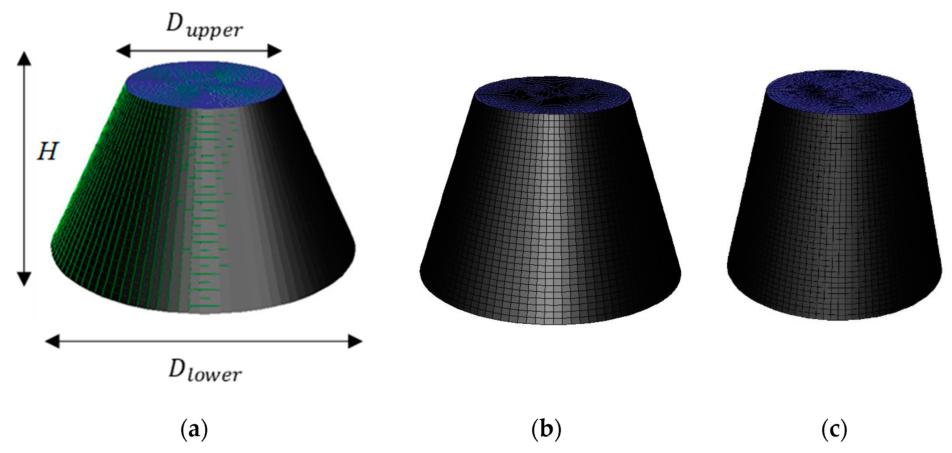
When designing thermal energy storage systems, a trade-off is usually encountered between heat losses and pressure losses. These factors are also usually related to the physical footprint of the system, i.e., space restrictions. However, studies show that it is possible to find an ideal aspect ratio, like the best one for a truncated cone-shaped TES system ( γ = H / D u p p e r , where H is height and Dupper is upper diameter) being higher than one [26]. It is important to note that economic and technical limitations are commonly related to the mentioned challenges and directly affect the design of the system. Having all that in mind, three aspect ratios were selected for the rock bed proposed here. The ratios range from 1.0 to 1.35 and were fashioned based on a constant volume of 1830 m3. The truncated cone-shaped domains have three distinct heights, 10 m, 12 m, and 13.5 m, and can be seen in Figure 4a–c, respectively. All shapes have an invariable upper diameter (Dlower) of 10 m, and a lower diameter ranging from 20 to 16 m.

2.3. Thermophysical Properties

In this study, the rock thermophysical properties were considered constant, while the air thermophysical properties were defined as functions of temperature. The main properties for the storage domain (solid material) are compiled in Table 1.
As the proposed TES in this study aims to be charged with high-temperature exhaust air around 120 °C, and discharged with ambient-temperature in winter around 7 °C, it is crucial to correlate the properties of air (i.e., density, thermal conductivity, and viscosity) with temperature. Numerous equations have been introduced in literature to compute the temperature-dependent thermal properties of air. Here, the following equations (Equations (10)–(12)) were used, which are valid in a range of −73 °C–200 °C [40].
ρ f = 351.99 T + 344.84 T 2
μ f = 1.4592 T 3 / 2 109.10 + T
k f = ( 2.3340 × 10 3 ) T 3 / 2 164.54 + T .
where ρ f is air density (kg/m3), μ f is air viscosity (10−6 N·s/m2), k f is air thermal conductivity (W/m·K), and T is the air temperature (Kelvin). Thus, user-defined functions (UDF) written in C language were used to account for the air thermal properties as a function of temperature.

2.4. Boundary Conditions

The current study takes into account the transient fluid flow that happens within the solid domain when it is crossed by the air. In the charging phase, the bottom of the bed is defined as pressure outlet, while the top is defined as a velocity inlet. Meanwhile, during the discharge phase, the boundaries are inverted and the ambient air (i.e., cold air) is injected from the bottom of the TES system. Seeking to take advantage of the possible buoyancy effects that may happen when the cold and hot air are present inside the rock bed, the hot inlet air (at fixed 120 °C) is injected through the top of the system, whereas the cold air in the discharge stage is injected through the bottom. Besides, the lateral boundaries of the system are considered insulated (zero heat flux) and with no slip (zero velocity).

2.5. Mesh Independency Study

In order to make sure the results obtained independent of the mesh refinement for the model developed, three meshes with distinct levels of refinement were created with 8.5 × 10 4 , 1.54 × 10 5 , and 2.86 × 10 5 elements, respectively. The mesh containing about 1.54 × 10 5 elements results in a 2% deviation in terms of pressure drop and outlet temperature, compared to the mesh with around 2.86 × 10 5 elements. The deviation in results is found to be about 9% between the coarsest mesh (containing 8.5 × 10 4 elements) and the finest one ( 2.86 × 10 5 elements). Thus, the intermediate mesh consisting of around 1.54 × 10 5 elements was chosen for all the further numerical investigations.

3. Results and Discussion

3.1. Validation of the Model

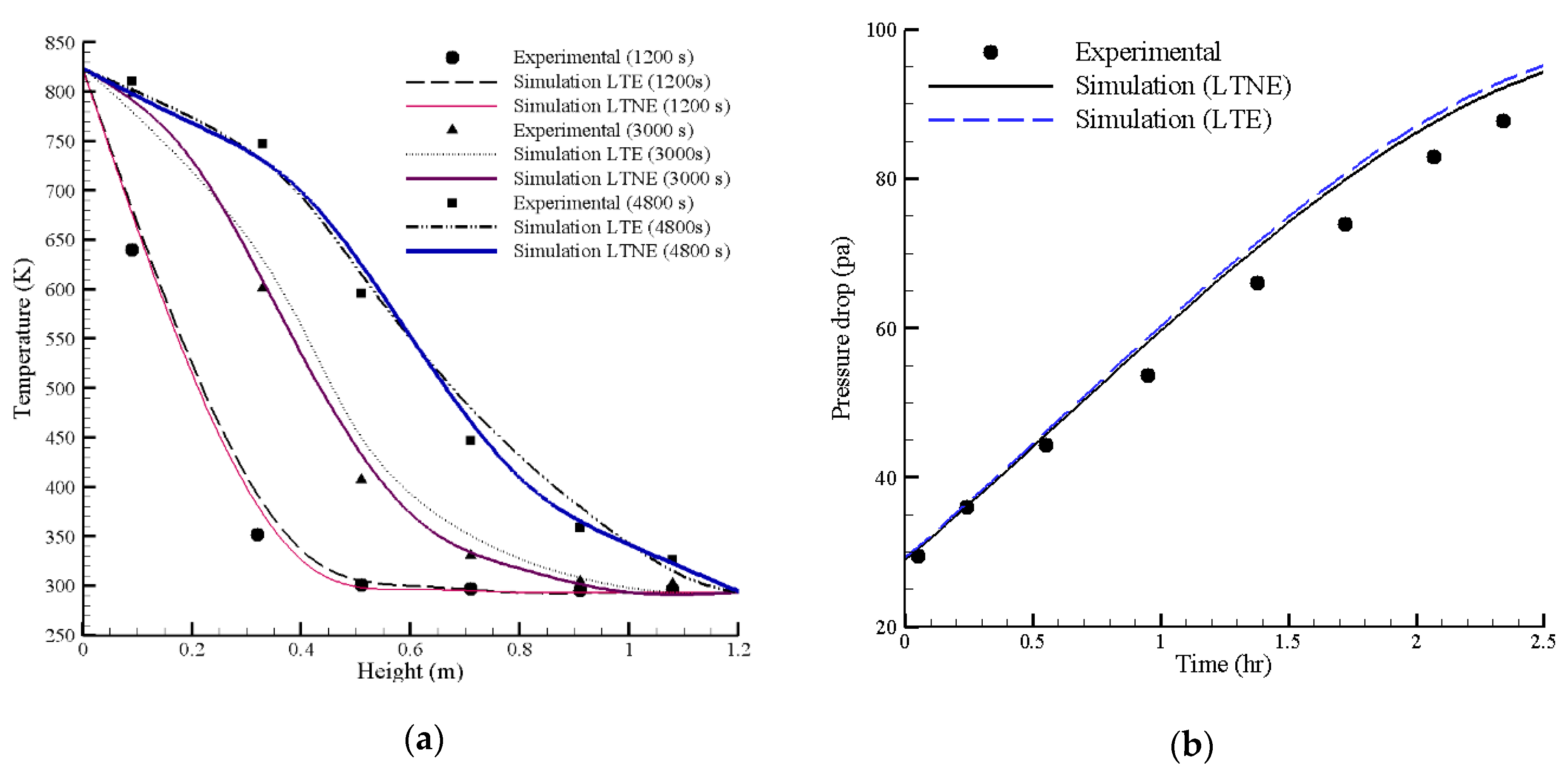
An essential step of the implementation of heat transfer and fluid flow model on the prediction of real-case system performance is the validation of its results against outcomes of an experimental system. It is essential to prove that the proposed model is able to capture the real phenomena experienced by the porous media domain while used as TES. Here, the pilot-test data presented by Hänchen et al. [28] was used for experimental validation. Dimensions were rescaled, and the boundary conditions were readjusted to conform with the heat storage system proposed there. Hence, the model was run considering both the LTE and LTNE approaches. This was performed seeking the best match for the numerical model and the experimental results. The results are shown in Figure 5a for temperature distribution within the rock bed at different points in time, allowing for the validation of heat transfer, while Figure 5b depicts a comparison of pressure drop development across the bed with time, allowing validation of fluid flow. Both temperature and pressure can be seen to agree well with the experimental results. It is important to note that, although LTE and LTNE results are very similar for pressure drop, they are significantly different for temperature distribution across the bed, with LTNE being closer to the experimental ones. This is particularly true as temperatures develop with time. For that reason, the LTNE method, despite being more computationally intensive, was chosen for all the following simulations presented in this study.

3.2. Parametric Analysis

3.2.1. Aspect Ratios (Rock-Bed Shape)

It is expected that the dimensions of the TES system will affect the configuration of the fluid flow profiles and velocity contours within the porous media, thus impacting the ratio of heat transfer and the capacity of the system to store heat. Due to that, the distinct geometries previously presented were used throughout the study to show the impact of several parameters in the fluid flow and heat transfer of rock beds of different dimensions. Figure 6 depicts the contours for velocity inside the rock bed, in the storage period, for all the proposed aspect ratios. The selected values for inlet velocity being 0.05 m/s, the porosity 0.2, and an average particle size of 1.0 m (here considered the base case). It can be seen that having a lower aspect ratio causes higher velocity gradients to happen, leading to a lower exit velocity of air. This is reasonable, since the outlet has a greater area in that case. It should be noted that, for higher mass flows (and consequently higher Reynolds numbers), the exploitation rate, along with the energy efficiency of the system, declines [41]. The reason for this being that the residence time of the HTF inside the bed is reduced as an effect of the lower fluid velocities, which, per se, decreases the opportunity for heat exchange. Therefore, it is important to note that, to improve heat exchange rate within the system, an optimum fluid velocity should be found for each application.

3.2.2. Effect of Porosity, Particle Size and Fluid Velocity

Simulations were performed with distinct porosities, particle diameter, and velocities for all the aspect ratios. The HTF inlet velocity was tested from 0.01 to 0.07 m/s, while the porosity was varied from 0.2 to 0.5. Results from simulations with distinct porosities and aspect ratios are shown in Figure 7a–c for the charging, and Figure 7d–f for the discharging, cycles. It can be seen that the outlet temperature for the air continuously increases during the charging period up to almost 120 °C, which makes the inlet and outlet temperature differential no more than 1 °C. It is also visible that when using greater fluid velocities (and consequently larger mass flows), temperature raise is much faster becoming practically independent from the porosity of the bed and the aspect ratio. The same can be said for the discharging cycle, in which the drop in outlet temperature is equally fast.
Having in mind the obtained outcomes, it is possible to calculate the total energy stored in the system. The evaluations show that about 540 GJ can be stored on the bed with a porosity of 0.2, and about 350 GJ on the one with 0.35, while the intermediate porosity leads to a total of 450 GJ. The idea is that this heat that was stored can be withdrawn from the TES system in a cold season, i.e., when demand is excessive, and be employed in a wide range of potential applications. Figure 8 shows that, by increasing porosity in the system, a direct decrease in total energy stored is encountered, mainly due to the reduction of mass for a domain with constant total volume. On the other hand, aspect ratio and rock particle size are not seen to have significant effects in the stored/extracted capacity, which is the reason why Figure 8 only shows results for one case of each. It is also worth noting that, even though the total energy stored in the system slightly increases for higher mass flow rates, lower velocities can provide a longer charging/discharging period for the TES system. Finally, it is possible to conclude that the total heat storing capacity of the system is virtually the same for all the distinct aspect ratios and Reynolds tested, which leads us to believe that such capacity is nearly entirely dependent on the mass of the storage media.
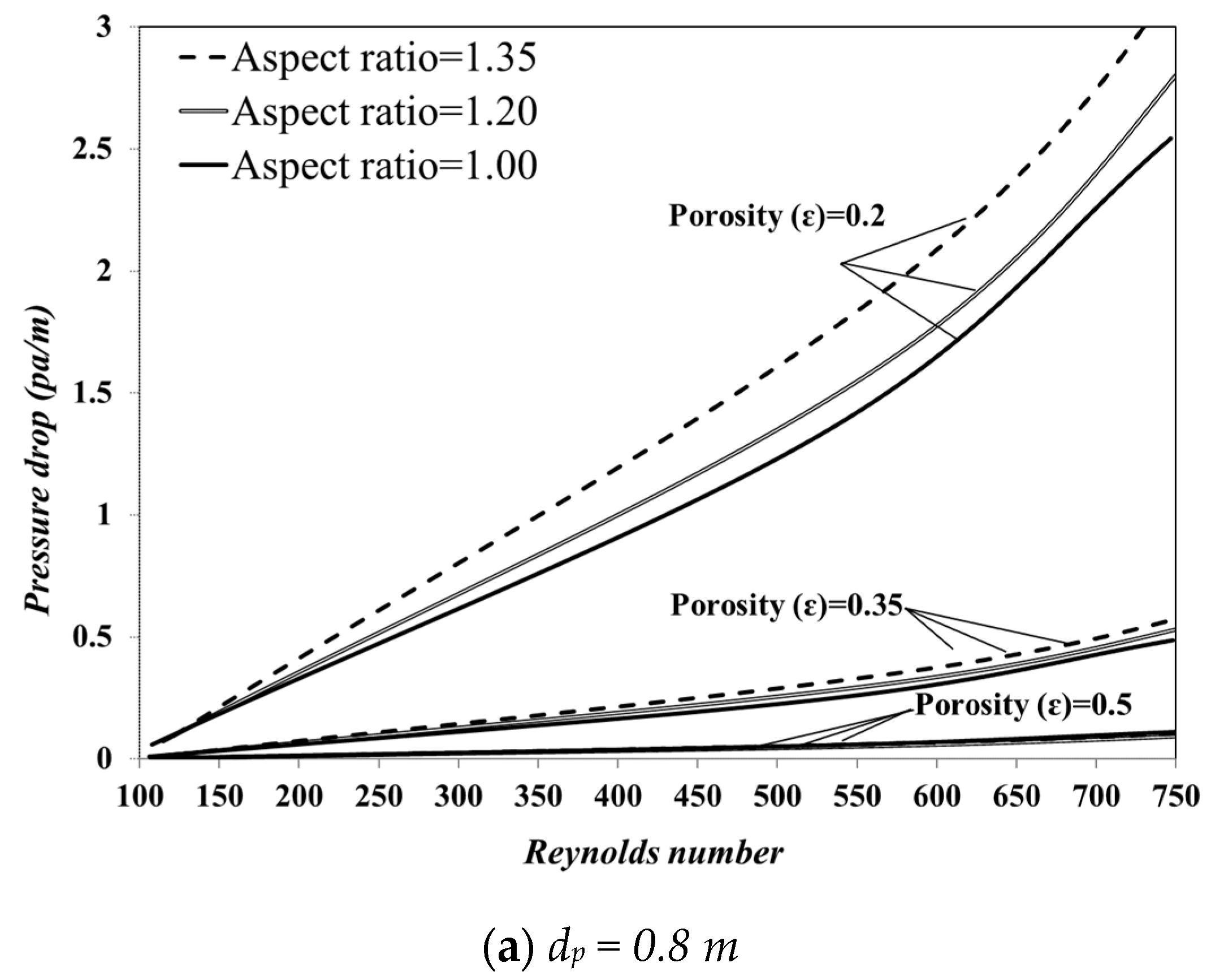
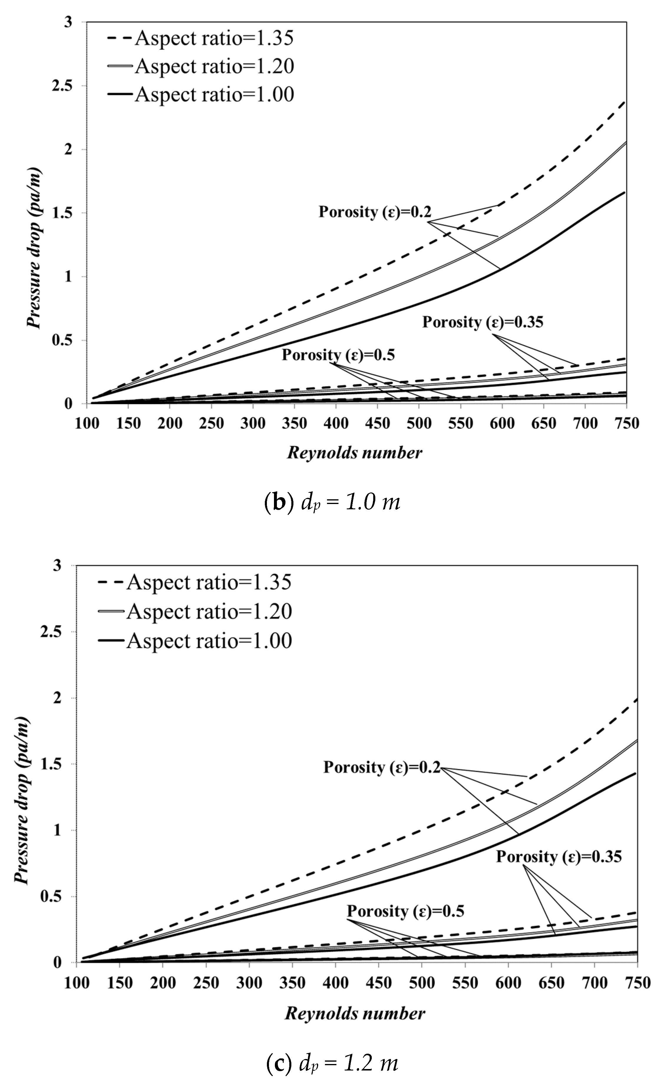
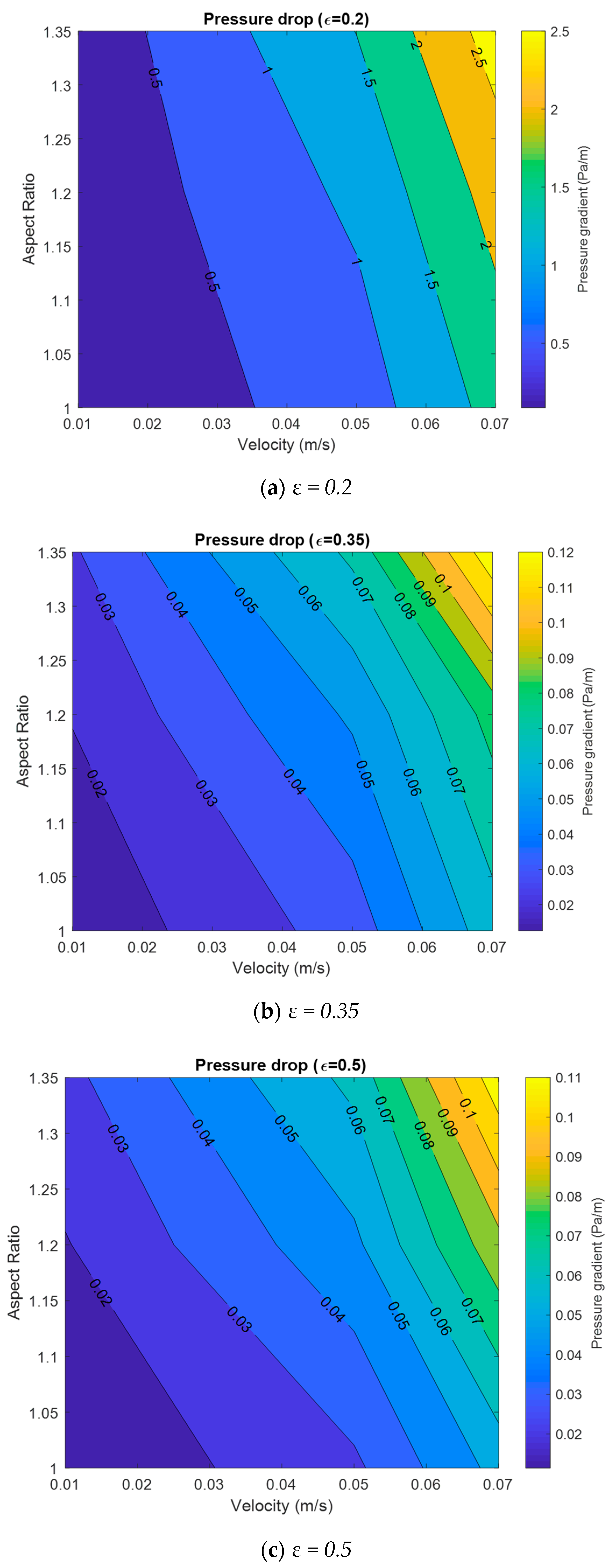
To evaluate the impact of these parameters on the pressure drop through the bed, the Reynolds number of the flow was varied from 100 to 750 and, through numerical calculations, the pressure drop across the system was calculated numerically. The results that can be seen in Figure 9 show the development of pressure gradient across the bed with Reynolds number. In addition, Figure 10 shows contours for maximum pressure gradient across the system against aspect ratio and inlet velocity for a constant particle size of 1.0 m. Figure 9 shows that, even though pressure drop increases with velocity for all scenarios, the growth is very subtle for higher porosities, being even an order of magnitude lower than that for a low porosity (and consequently low permeability). The same happens for the slight increase in pressure difference seen in larger aspect ratios, which only becomes significant at lower porosities. Perhaps this effect can be more clearly identified in Figure 10, as it shows the maximum pressure gradient contours growing rapidly with velocity, as opposed to γ, but being considerably low except for the lowest porosity. With that in mind, it can be understood that the permeability of the packed bed (direct consequence of the domain particle size and porosity) impacts the pressure drop in a more accentuated way than the change in shape does. It is important to mention that greater velocity of the HTF causes more significant pressure decrease across the bed; this means more power will be necessary from fans generating the flow for two aspects, to overcome the higher pressure drop and to create the larger mass flow itself.

3.2.3. Effect of Rock Thermophysical Properties

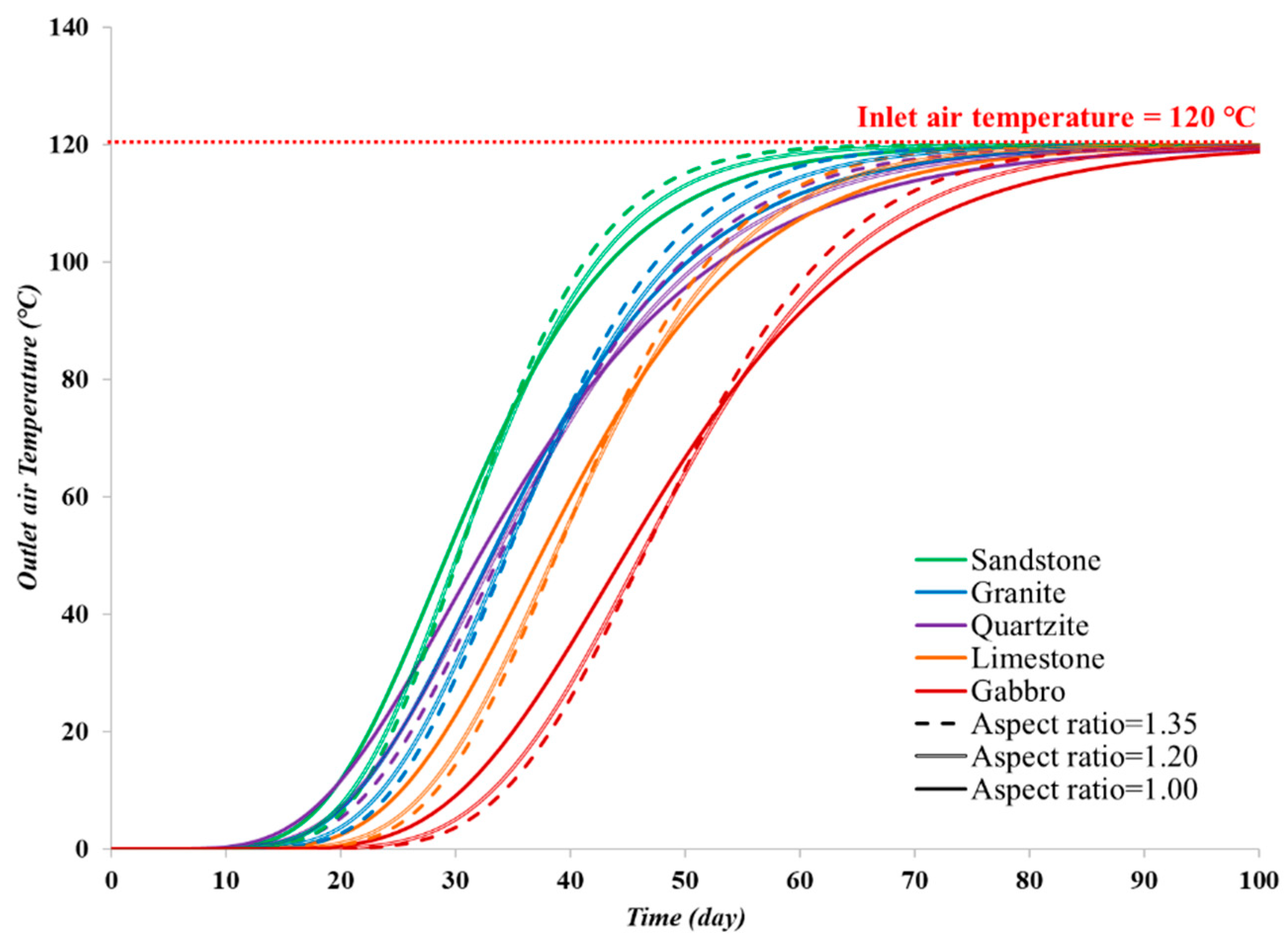
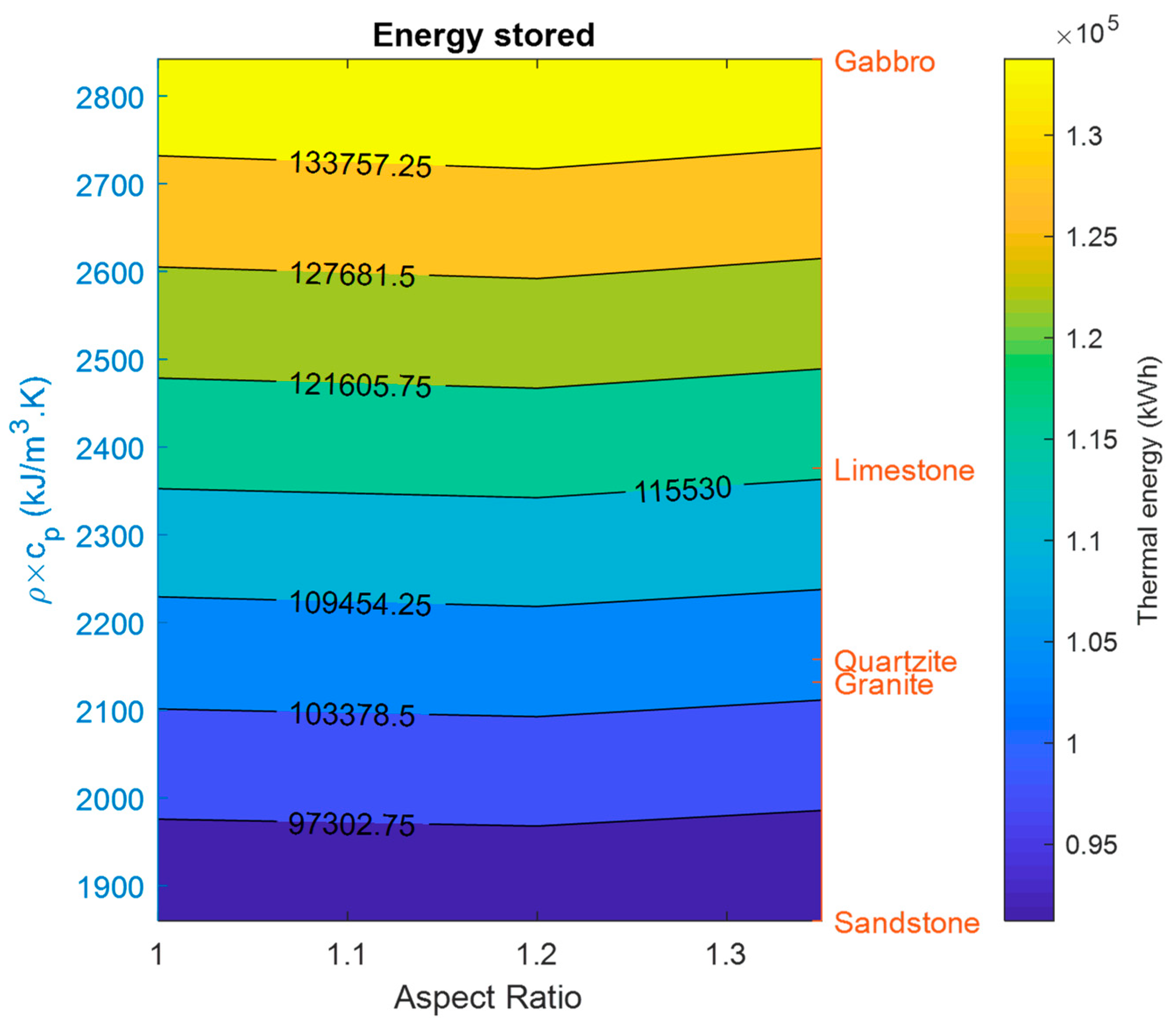
Bear in mind that for a constant volume of rock (i.e., constant mass of storage material in the domain), an improvement in the natural capacity of the material to store thermal energy (i.e., ρ and cp) would lead to an enhancement of the TES system. For that reason, different rock types were investigated for the task proposed. Five types of rock were selected, and their thermophysical properties were taken from literature [42] and are given in Table 2. The results for outlet fluid temperature during the charging cycle can be seen in Figure 11. It is noticeable that the highest impacting factor is the thermal capacity of the rock (the product of density and specific heat). As shown, sandstone (lowest thermal capacity) quickly achieves its maximum temperature, while gabbro (highest thermal capacity) takes the longest time to be fully charged. This can also be noticed from the similarity between the quartzite and the granite temperature profiles, even with very distinct values for k. The thermal conductivity has a subtle effect on the charging rate, being slightly more accentuated for smaller aspect ratios. Except for that, the aspect ratio has a small impact on charging rate, mainly caused by the higher velocities of fluid within the bed (as previously mentioned in Section 3.2.1). However, its effect on the total energy storage is virtually null, as shown in Figure 12.

3.2.4. Carbon Emission Reduction

To further demonstrate the benefits of the system, the carbon footprint reduction introduced by its use was evaluated using emission data from literature [43,44]. Assuming the system substitutes natural gas as a heating source, which has carbon emissions of approximately 510 tons of carbon dioxide equivalent (CO2eq) per GWh, the total amount of carbon footprint reduction was estimated. It was found that for the base properties, the proposed TES (with a volume of 1830 m3, corresponding to 5490 tons of rock) would be able to reduce emissions in about 156 tons of CO2eq per year, for all the aspect ratios. This is equivalent to 85 tons of CO2eq/m3 of rock per year, or 28 tons of CO2eq/ton of rock per year. It is important to note that for a system replacing coal (∼905 tons of CO2eq per GWh) or heating oil (∼730 tons of CO2eq per GWh), the decrease in carbon footprint could be even more significant, these being displayed in Table 3.

4. Conclusions

In this study, a three-dimensional transient model was established to study the heat transfer and fluid flow in a thermal energy storage system consisting of a truncated cone-shaped bed of packed rocks. A considerable number of simulations were performed to account for the impact of all the distinct parameters (aspect ratio, HTF velocity, bed porosity, particle size, and thermophysical properties) and their combination in performance of the system. The study shows that porous media properties of the system, such as porosity, are extremely important in the performance of the system as a TES system, regarding both charging rate, energy stored/extracted, and pressure drop. The aspect ratio however, here evaluated in a series of combinations with other parameters, was shown not to have a significant effect in anything but the total pressure gradients across the system. Through the change in fluid velocity across the system, the pressure drop was also analyzed. It was shown that the pressure differential across the system quickly increases for increments in Reynolds number or a decrease in porosity. Particle size was also considered, and does not appear to significantly influence the heat transfer, having an effect mostly on permeability and, as a result, on pressure drop. A few different rock types were investigated, and it was seen that the most important thermophysical parameter for a rock bed, in terms of heat storage, is the thermal capacity. Some estimations of the environmental benefits of the system were also made, showing that it could lead to a carbon footprint reduction (from heating systems) of around 85–150 tons of CO2eq per cubic meter of rock per year.
Finally, such outcomes can be effectively implemented in the design and performance optimization of thermal energy storage systems based on packed rock material consisting of large particles, such as the ones found in caved zones. Using the domain with the most appropriate properties ought to bring significant savings in energy for a site implementing the technique, such as a remote (and cold) area, both commercial (such as mining operations) and non-commercial (such as first nation dwellings) in applications, such as heating for communal areas, domestic hot water provision, or even mine ventilation.

Author Contributions

L.A.: conceptualization, investigation, methodology, software, validation, writing—original draft, writing—review and editing; M.A.R.d.B.: conceptualization, validation, writing—review and editing; S.A.G.-M.: conceptualization, validation, writing—review and editing; A.P.S.: conceptualization, validation, resources, supervision, writing—review and editing; N.B.: supervision, writing—review and editing; F.P.H.: supervision, writing—review and editing. All authors have read and agreed to the published version of the manuscript.

Funding

This research received no external funding.

Acknowledgments

The first author acknowledges the financial support provided by the Killam Trusts fund scholarships and Dalhousie University.

Conflicts of Interest

The authors declare no conflict of interest.

Nomenclature

Aspecific surface area (m−1);
cpisobaric specific heat (J/kg-K);
daverage particle diameter (m);
Dcone diameter (m);
hconvection heat transfer coefficient (W/m2-K);
Hcone height (m);
kthermal conductivity (W/m-K);
Kpermeability (m2);
NuNusselt number (non-dimensional);
pstatic pressure (Pa);
PrPrandtl number (non-dimensional);
ReReynolds number (non-dimensional);
Ttemperature (K);
usuperficial velocity vector (m/s).
Abbreviations
CFDcomputational fluid dynamics;
CSPconcentrated solar power;
HTCheat transfer coefficient;
HTFheat transfer fluid;
LTElocal thermal equilibrium;
LTNElocal thermal non-equilibrium;
REVrepresentative elementary volume;
SIMPLEsemi-implicit method for pressure-linked equation;
TESthermal energy storage;
UDFuser-defined function;
VAMvolume average model.
Greek letters
αviscous resistance coefficient;
βinertial resistance coefficient;
γaspect ratio;
εporosity (void fraction);
ρdensity;
μdynamic viscosity.
Subscripts and superscripts
*ancillary;
eqequivalent;
ffluid phase;
fsinterphase (fluid-solid) property;
lowercone base;
pparticle;
ssolid phase;
uppercone top.

References

  1. Krishan, O.; Suhag, S. An updated review of energy storage systems: Classification and applications in distributed generation power systems incorporating renewable energy resources. Int. J. Energy Res. 2019, 43, 6171–6210. [Google Scholar] [CrossRef]
  2. Sarbu, I.; Dorca, A. Review on heat transfer analysis in thermal energy storage using latent heat storage systems and phase change materials. Int. J. Energy Res. 2019, 43, 29–64. [Google Scholar] [CrossRef] [Green Version]
  3. Sorgulu, F.; Dincer, I. Design and analysis of a solar tower power plant integrated with thermal energy storage system for cogeneration. Int. J. Energy Res. 2019, 43, 6151–6160. [Google Scholar] [CrossRef]
  4. Abdel-Salam, M.; Aly, S.; El-Sharkawy, A.; Abdel-Rehim, Z. Thermal characteristics of packed bed storage system. Int. J. Energy Res. 1991, 15, 19–29. [Google Scholar] [CrossRef]
  5. Dincer, I. Thermal energy storage systems as a key technology in energy conservation. Int. J. Energy Res. 2002, 26, 567–588. [Google Scholar] [CrossRef]
  6. Tian, Y.; Zhao, C.-Y. A review of solar collectors and thermal energy storage in solar thermal applications. Appl. Energy 2013, 104, 538–553. [Google Scholar] [CrossRef] [Green Version]
  7. Zanganeh, G.; Pedretti, A.; Zavattoni, S.; Barbato, M.; Steinfeld, A. Packed-bed thermal storage for concentrated solar power–Pilot-scale demonstration and industrial-scale design. Sol. Energy 2012, 86, 3084–3098. [Google Scholar] [CrossRef]
  8. Mertens, N.; Alobaid, F.; Frigge, L.; Epple, B. Dynamic simulation of integrated rock-bed thermocline storage for concentrated solar power. Sol. Energy 2014, 110, 830–842. [Google Scholar] [CrossRef]
  9. Schmidt, T.; Mangold, D.; Müller-Steinhagen, H. Central solar heating plants with seasonal storage in Germany. Sol. Energy 2004, 76, 165–174. [Google Scholar] [CrossRef]
  10. Dahash, A.; Ochs, F.; Janetti, M.B.; Streicher, W. Advances in seasonal thermal energy storage for solar district heating applications: A critical review on large-scale hot-water tank and pit thermal energy storage systems. Appl. Energy 2019, 239, 296–315. [Google Scholar] [CrossRef]
  11. Raftery, A.; Shier, P.; Obilade, T. Domestic space-heating and solar energy in Ireland. Int. J. Energy Res. 1980, 4, 31–39. [Google Scholar] [CrossRef]
  12. Dincer, I.; Dost, S. A perspective on thermal energy storage systems for solar energy applications. Int. J. Energy Res. 1996, 20, 547–557. [Google Scholar] [CrossRef]
  13. Singh, P.L.; Deshpandey, S.; Jena, P. Thermal performance of packed bed heat storage system for solar air heaters. Energy Sustain. Dev. 2015, 29, 112–117. [Google Scholar] [CrossRef]
  14. Ghoreishi-Madiseh, S.A.; Fahrettin Kuyuk, A.; Rodrigues de Brito, M.A.; Baidya, D.; Torabigoodarzi, Z.; Safari, A. Application of borehole thermal energy storage in waste heat recovery from diesel generators in remote cold climate locations. Energies 2019, 12, 656. [Google Scholar] [CrossRef] [Green Version]
  15. Ghoreishi-Madiseh, S.A.; Safari, A.; Amiri, L.; Baidya, D.; de Brito, M.A.R.; Kuyuk, A.F. Investigation of viability of seasonal waste heat storage in rock piles for remote communities in cold climates. Energy Procedia 2019, 159, 66–71. [Google Scholar] [CrossRef]
  16. Zanganeh, G.; Pedretti, A.; Haselbacher, A.; Steinfeld, A. Design of packed bed thermal energy storage systems for high-temperature industrial process heat. Appl. Energy 2015, 137, 812–822. [Google Scholar] [CrossRef]
  17. Baidya, D.; de Brito, M.A.R.; Sasmito, A.P.; Scoble, M.; Ghoreishi-Madiseh, S.A. Recovering waste heat from diesel generator exhaust; an opportunity for combined heat and power generation in remote Canadian mines. J. Clean. Prod. 2019, 225, 785–805. [Google Scholar] [CrossRef]
  18. Ould Amrouche, S.; Rekioua, D.; Rekioua, T.; Bacha, S. Overview of energy storage in renewable energy systems. Int. J. Hydrog. Energy 2016, 41, 20914–20927. [Google Scholar] [CrossRef]
  19. Welsch, B.; Göllner-Völker, L.; Schulte, D.O.; Bär, K.; Sass, I.; Schebek, L. Environmental and economic assessment of borehole thermal energy storage in district heating systems. Appl. Energy 2018, 216, 73–90. [Google Scholar] [CrossRef]
  20. Galione Klot, P.A.; Pérez Segarra, C.D.; Rodríguez Pérez, I.M.; Torras Ortiz, S.; Rigola Serrano, J. Numerical evaluation of multi-layered solid-PCM thermocline-like tanks as thermal energy storage systems for CSP applications. Energy Procedia 2015, 69, 832–841. [Google Scholar] [CrossRef] [Green Version]
  21. Amiri, L.; Ghoreishi-Madiseh, S.A.; Sasmito, A.P.; Hassani, F.P. Effect of buoyancy-driven natural convection in a rock-pit mine air preconditioning system acting as a large-scale thermal energy storage mass. Appl. Energy 2018, 221, 268–279. [Google Scholar] [CrossRef]
  22. Amiri, L.; Ghoreishi-Madiseh, S.A.; Sasmito, A.P.; Hassani, F.P. Evaluation of Heat Transfer Performance between Rock and Air in Seasonal Thermal Energy Storage Unit. Appl. Energy 2017, 142, 576–581. [Google Scholar] [CrossRef]
  23. Ghoreishi-Madiseh, S.A.; Amiri, L.; Sasmito, A.P.; Hassani, F.P. A conjugate natural convection model for large scale seasonal thermal energy storage units: Application in mine ventilation. Energy Procedia 2017, 105, 4167–4172. [Google Scholar] [CrossRef]
  24. Ghoreishi-Madiseh, S.A.; Sasmito, A.P.; Hassani, F.P.; Amiri, L. Performance evaluation of large scale rock-pit seasonal thermal energy storage for application in underground mine ventilation. Appl. Energy 2017, 185, 1940–1947. [Google Scholar] [CrossRef]
  25. Ghoreishi-Madiseh, S.A.; Sasmito, A.P.; Hassani, F.P.; Amiri, L. Heat transfer analysis of large scale seasonal thermal energy storage for underground mine ventilation. Energy Procedia 2015, 75, 2093–2098. [Google Scholar] [CrossRef] [Green Version]
  26. Singh, H.; Saini, R.; Saini, J. A review on packed bed solar energy storage systems. Renew. Sustain. Energy Rev. 2010, 14, 1059–1069. [Google Scholar] [CrossRef]
  27. Arias, D.A.; McMahan, A.C.; Klein, S.A. Sensitivity of long-term performance simulations of solar energy systems to the degree of stratification in the thermal storage unit. Int. J. Energy Res. 2008, 32, 242–254. [Google Scholar] [CrossRef]
  28. Hänchen, M.; Brückner, S.; Steinfeld, A. High-temperature thermal storage using a packed bed of rocks–heat transfer analysis and experimental validation. Appl. Therm. Eng. 2011, 31, 1798–1806. [Google Scholar] [CrossRef]
  29. Barton, N. Simulations of air-blown thermal storage in a rock bed. Appl. Therm. Eng. 2013, 55, 43–50. [Google Scholar] [CrossRef]
  30. Kuravi, S.; Trahan, J.; Goswami, Y.; Jotshi, C.; Stefanakos, E.; Goel, N. Investigation of a high-temperature packed-bed sensible heat thermal energy storage system with large-sized elements. J. Sol. Energy Eng. 2013, 135, 041008. [Google Scholar] [CrossRef]
  31. Cascetta, M.; Cau, G.; Puddu, P.; Serra, F. A comparison between CFD simulation and experimental investigation of a packed-bed thermal energy storage system. Appl. Therm. Eng. 2016, 98, 1263–1272. [Google Scholar] [CrossRef]
  32. Agrawal, P.; Gautam, A.; Kunwar, A.; Kumar, M.; Chamoli, S. Performance assessment of heat transfer and friction characteristics of a packed bed heat storage system embedded with internal grooved cylinders. Sol. Energy 2018, 161, 148–158. [Google Scholar] [CrossRef]
  33. Rodat, S.; Bruch, A.; Dupassieux, N.; El Mourchid, N. Unique Fresnel demonstrator including ORC and thermocline direct thermal storage: Operating experience. Energy Procedia 2015, 69, 1667–1675. [Google Scholar] [CrossRef] [Green Version]
  34. Amiri, L.; Ghoreishi-Madiseh, S.A.; Hassani, F.P.; Sasmito, A.P. Friction factor correlation for airflow through broken rocks and its applications in mine ventilation. Int. J. Min. Sci. Technol. 2020, 30, 455–462. [Google Scholar] [CrossRef]
  35. Amiri, L.; Ghoreishi-Madiseh, S.A.; Hassani, F.P.; Sasmito, A.P. Estimating pressure drop and Ergun/Forchheimer parameters of flow through packed bed of spheres with large particle diameters. Powder Technol. 2019, 356, 310–324. [Google Scholar] [CrossRef]
  36. Royer, J. Status of remote/off-grid communities in Canada. Nat. Resour. Can. 2011. [Google Scholar]
  37. Whitaker, S. Flow in porous media I: A theoretical derivation of Darcy’s law. Transp. Porous Media 1986, 1, 3–25. [Google Scholar] [CrossRef]
  38. Nield, D.; Bejan, A. Convection in Porous Media, Fifth; Springer: New York, NY, USA, 2016. [Google Scholar]
  39. Ergun, S.; Orning, A.A. Fluid flow through randomly packed columns and fluidized beds. Ind. Eng. Chem. 1949, 41, 1179–1184. [Google Scholar] [CrossRef]
  40. McQuillan, F.; Culham, J.; Yovanovich, M. Properties of Some Gases and Liquids at One Atmosphere; Microelectronics Heat Transfer Laboratory Report UW/MHTL 8407 G-02; University of Waterloo: Waterloo, Belgium, 1984. [Google Scholar]
  41. Bruch, A.; Molina, S.; Esence, T.; Fourmigué, J.; Couturier, R. Experimental investigation of cycling behaviour of pilot-scale thermal oil packed-bed thermal storage system. Renew. Energy 2017, 103, 277–285. [Google Scholar] [CrossRef]
  42. Tiskatine, R.; Aharoune, A.; Bouirden, L.; Ihlal, A. Identification of suitable storage materials for solar thermal power plant using selection methodology. Appl. Therm. Eng. 2017, 117, 591–608. [Google Scholar] [CrossRef]
  43. Fundamentals, C. SI: Climatic Design Information; ASHRAE Handbook. Am. Soc. Heat. Refrig. 2013, 14, 111. [Google Scholar]
  44. Stritih, U.; Zavrl, E.; Paksoy, H.O. Energy Analysis and Carbon Saving Potential of a Complex Heating System with Solar Assisted Heat Pump and Phase Change Material (PCM) Thermal Storage in Different Climatic Conditions. Eur. J. Sustain. Dev. Res. 2019, 3, em0067. [Google Scholar] [CrossRef] [Green Version]
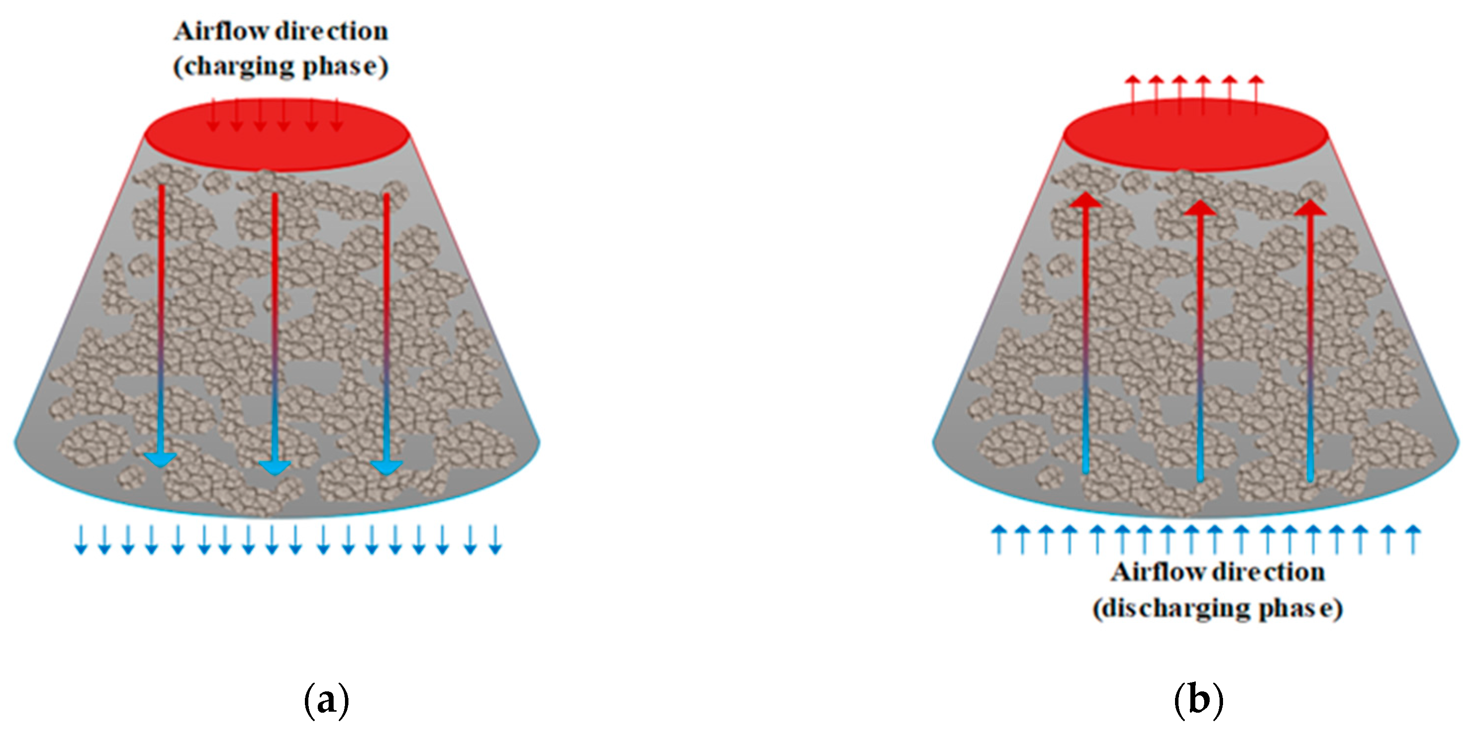
Figure 1. Packed rock bed with air flow indicated during (a) charge and (b) discharge cycles.
Applsci 10 07771 g001
Figure 2. The distinct heat transfer mechanisms taking place in a packed-rock thermal energy storage (TES).
Applsci 10 07771 g002
Figure 3. The representative elementary volume (REV).
Applsci 10 07771 g003
Figure 4. Proposed rock-bed thermal energy storage system shaped as a truncated cone with aspect ratios (γ): (a) 1.0, (b) 1.2, and (c) 1.35.
Applsci 10 07771 g004
Figure 5. Validation of the proposed model for both local thermal equilibrium (LTE) and local thermal non-equilibrium (LTNE) approaches against experimental results from [28]: (a) comparison of temperature along the vertical axis; (b) comparison of pressure drop along the rock bed.
Applsci 10 07771 g005
Figure 6. Velocity profiles for the proposed systems with a porosity of 0.2 and inlet fluid velocity of 0.05 m/s on the domains with aspect ratios of: (a) 1.0, (b) 1.2, and (c) 1.35.
Applsci 10 07771 g006
Figure 7. Outlet air temperatures (°C) in charging mode (left column) and discharging (right column) versus time for different aspect ratios and porosities: (a) and (d) ɛ = 0.2; (b) and (e) ɛ = 0.35; and (c) and (f) ɛ = 0.5.
Applsci 10 07771 g007
Figure 8. Contours of energy stored (a) and energy extracted (b) from the volume-averaged model (VAM) simulation for aspect ratio (AR) = 1.0 and Particle diameter (dp) = 1.0 m.
Applsci 10 07771 g008
Figure 9. Pressure gradients ( p / L ) as a function of Reynolds number obtained in the volume-averaged model simulations with distinct aspect ratios and porosities with (a) particle diameter 0.8 m, (b) 1.0 m, and (c) 1.2 m.
Applsci 10 07771 g009aApplsci 10 07771 g009b
Figure 10. Pressure gradient ( p / L ) versus aspect ratio and inlet velocity obtained with the volume-averaged model using diverse porosities: (a) ε = 0.2, (b) ε = 0.35, and (c) ε = 0.5.
Applsci 10 07771 g010
Figure 11. Outlet temperature in charging phase for distinct types of rock.
Applsci 10 07771 g011
Figure 12. Total energy stored versus thermal capacity of the rocks simulated, and aspect ratio.
Applsci 10 07771 g012
Table 1. Thermal energy storage material (rock) thermophysical properties.
Propertycp,sρsksdp
Value1000 (J/kg·K)3000 (kg/ m 3 )2.68 (W/m·K)0.8, 1.0, and 1.2 (m)
Table 2. Properties of the distinct rock types analyzed, taken from [42].
Rock Type Density   ( kg / m 3 ) Thermal   Conductivity   ( W / m · K ) Specific   Heat   ( j / kg   K ) Thermal   Capacity   ( kJ / m 3 · K )
Quartzite26005.08302158
Granite26002.88202132
Sandstone24002.37751860
Limestone27002.28802376
Gabbro29002.29802842
Table 3. Estimated carbon footprint reduction for heating using the proposed system (base properties).
UnitNatural GasOilCoal
Tons CO2eq/year156223276
Tons CO2eq/(m3.year)85122151
Tons CO2eq/(Ton rock.year)284150
Publisher’s Note: MDPI stays neutral with regard to jurisdictional claims in published maps and institutional affiliations.