Article

Influence of Smart Spring Support Parameters on Vibration Characteristics of Three Support Shafting

National Key Laboratory of Science and Technology on Helicopter Transmission, Nanjing University of Aeronautics and Astronautics, Nanjing 210016, China
*
Author to whom correspondence should be addressed.
Appl. Sci. 2020, 10(21), 7752; https://doi.org/10.3390/app10217752
Submission received: 9 October 2020 / Revised: 28 October 2020 / Accepted: 28 October 2020 / Published: 2 November 2020

Abstract

:
Smart spring support is a kind of active damping device based on piezoelectric material. It can effectively suppress the vibration of a shaft system in an overly critical state by changing the stiffness and damping of the support. The support parameters have a significant impact on the vibration of the system. By studying the influence of the smart spring support parameters on the vibration characteristics of the transmission shaft system, the support parameters can be configured more reasonably so that the vibration of the transmission system can be reduced as much as possible. Based on the finite element method, this paper studies the influence of the stiffness, damping and mass of the smart spring support on the vibration characteristics of the three-support shafting. Firstly, the smart spring shafting test bed is built, and the vibration reduction performance test of the smart spring is carried out to verify the damping effect of the smart spring. Then, the shafting dynamic model is established by the finite element method, and the inherent characteristics of the system are analyzed. Finally, the influence of the stiffness, damping, mass and other parameters of the smart spring support on the dynamic response of the system is studied. The results show that increasing the stiffness of the smart spring support can effectively reduce the vibration amplitude of the system. The damping of the smart spring support has no obvious effect on the vibration of the shafting. The smaller the mass of the smart spring support, the more favorable the system is.

1. Introduction

Multi-support shafting is widely used in aviation and industrial fields, and it has an important impact on the overall performance of the equipment. With the development of high-speed and flexible multi-support shafting, the bending vibration of shafting is becoming more and more serious. At present, there are mainly a few vibration control methods: dynamic balance, passive control and active control [1]. Active control technology attenuates the vibration by actively applying control force. Smart spring support is an active damping device with variable stiffness and damping, which includes the main support (the elastic support of shaft system itself) and the auxiliary support. In regulating the force of input of the piezoelectric actuator on the auxiliary support, friction elements on the main and secondary support generate a positive pressure, the dry friction of which absorbs vibration energy [2]. The vibration reduction technology of the smart spring was first used in helicopter blade vibration control. Nitzsche et al. improved the active pitch link (APL) of the damper and tested the improved damping performance in the rotating tower test in 2013. The results showed that the APL could effectively reduce the vibration response and the transfer power of the blade [3]. Afagh et al. placed the smart spring mechanism on the blade load transfer path to achieve the purpose of reducing vibrations and to examine blade stability in the elastodynamic state [4]. Coppoetelli et al. conducted research on the dynamic properties of the smart spring on non-rotating helicopter leaves, as well as analysis of the impact of the smart spring on the properties of the models [5]. Grewal et al. designed a control scheme to make the stiffness of the smart spring device continuously change and compared the control effect of the state-switching control algorithm [6]. Li Miaomiao et al. studied the control strategy of the smart spring and carried out the critical vibration control of the transmission shaft system with a smart spring [7].
The influence of support parameters on the vibration characteristics of shafting is mainly focused on the influence of support stiffness and support position. In the study of bearing parameters in support of the vibration characteristics of the system, Li Quanchao et al. established the finite element model of the ship shafting bearing base system, analyzed the influence of bearing stiffness at the support and the base stiffness on the vibration transmission characteristics of the system. It was concluded that the change of support stiffness would affect the transverse vibration mode of shafting, and the change of stiffness of the oil-lubricated bearing had little effect on vibration transmission [8]. Li Haifeng established a dynamic model of ship propulsion shafting, based on the transfer matrix method, and analyzed the influence of bearing stiffness on the shafting vibration transmission path. The research results showed that the stern bearing stiffness had the greatest impact on the shafting vibration transmission, and the thrust bearing had the least impact [9]. Li Xiaojun studied the influence of changes in bearing stiffness on the transverse vibration of ship shafting and concluded that the natural frequency of the corresponding direction would be reduced when the bearing stiffness decreased [10]. The influence of bearing stiffness on the critical speed and response characteristics was studied in [11,12]. Ma Jun et al. studied the influence of dynamic stiffness and the damping coefficients of different bearings on the vibration characteristics of a rotor system [13]. Kumar theoretically studied the influence of journal bearings of different lengths on the dynamic characteristics of a rotor–bearing system [14]. Wang Bin studied the influence of bearing stiffness changes at different locations on the vibration characteristics of ship shafting [15]. Sun Bingnan et al. studied the influence of different bearing types and bearing length/diameter ratio parameters on vibration characteristics and concluded that, for the rotor system with an oil wedge bearing, the stability of large/long ratio journal bearing was better than that of short length/diameter ratio bearing, and the instability speed increased with the increase of the bearing’s length/diameter ratio [16]. Xu Junwei et al. analyzed the influence of bearing position and aperture change on the static stiffness and natural frequency of a motorized spindle in a rotor bearing system. It was concluded that an increase in span and aperture could improve the static stiffness of the spindle, and the change in bearing position at the back end obviously affected the frequency and mode of the spindle [17]. Su Chaojun et al. analyzed the influence of longitudinal stiffness change of the ship thrust bearing, stiffness change of the aft stern bearing support and position change on the natural frequency [18]. Zhang Xiaodong equated the bearing support to different support modes and studied the influence of the stern bearing under different support modes on the rotational vibration of shafting [19]. Jauhari adopted the optimization design method to optimize the bearing stiffness and damping, which could improve the stability of the system [20]. By using the Taguchi method, Yucel studied the vibration of a rotor system under different coupling types, disc positions and rotating speeds and found out the parameter combination which could minimize vibration deformation [21].
In summation, the research on smart springs is mainly on the torsional vibration control of helicopter blades. The influence of support parameters on the vibration characteristics of shafting is mainly about the influence of bearing stiffness and support position parameters on the vibration characteristics of the system, but research on the influence of support damping and support mass parameters on the vibration characteristics of shafting is less frequent. At present, research on reducing the vibration of the tail shaft with smart springs lacks theoretical orientation and verification. It is necessary to further study the application of smart springs in the vibration damping system of the tail drive shaft. Based on the finite element method, the finite element model of shafting is established. The influence of the smart spring support parameters on the dynamic response of the system is studied, which provides a reference for the structural design and vibration control of the smart spring support.

2. Vibration Reduction Test of Shafting with a Smart Spring

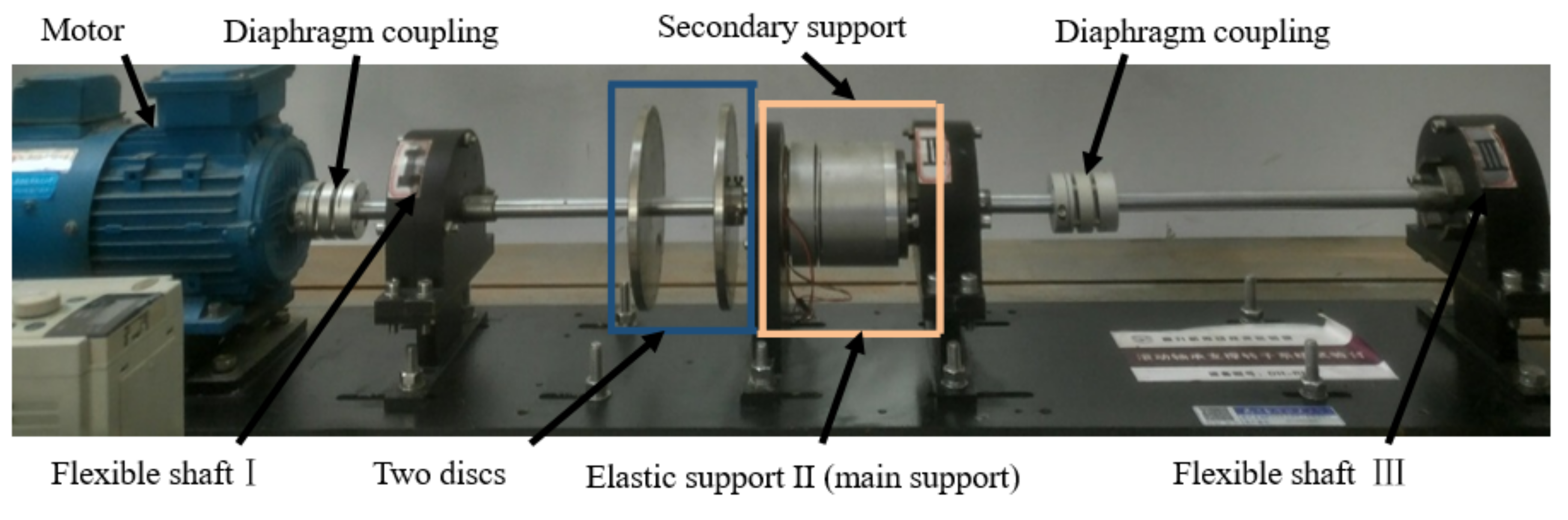
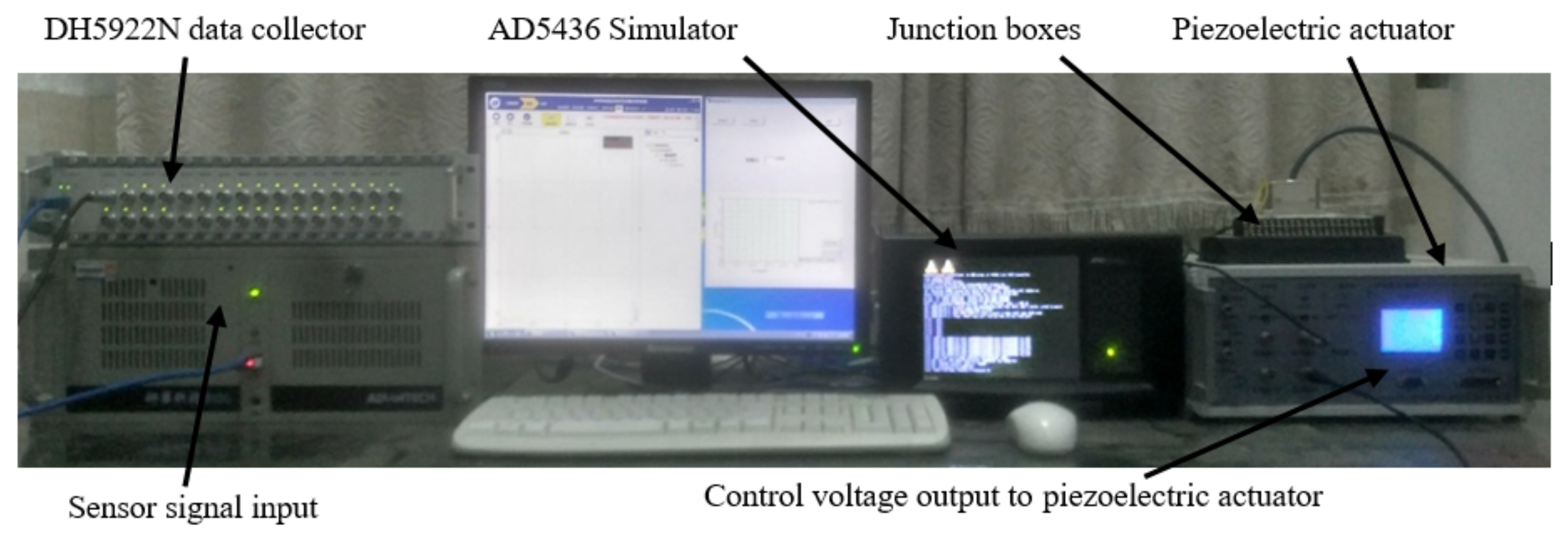
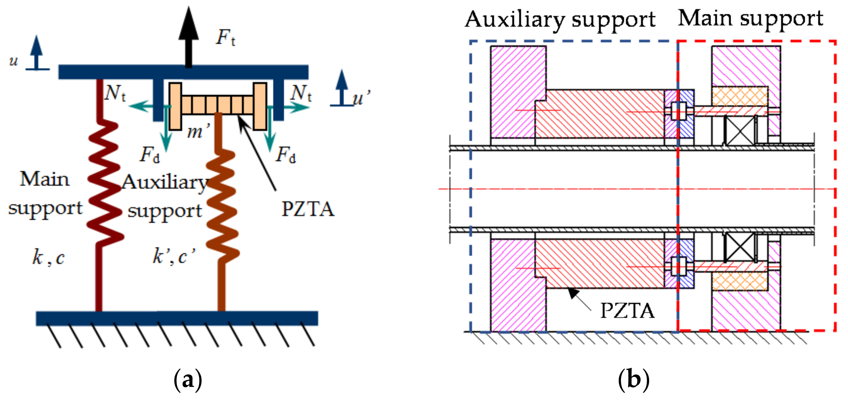
2.1. Design of Shafting Acceleration across a Critical Speed Test System

The test system consisted of a shafting test bed with a smart spring support, a management system, a data acquisition system and a control system. The management system consisted of a piezoelectric ceramic controller and a piezoelectric actuator. During the test, each increase of the output voltage of the 15 V piezoelectric ceramic wafers was recorded by a critical reaction, and the results were analyzed. The data acquisition system consisted of a sensor for acquiring and analyzing the dynamic signal of the system, a DH5922N data collector and the DHDAS support software. Control systems included an AD5436 controller and associated software. The range of the eddy current displacement sensor was from 0 mm to 4 mm, and the output voltage range was from −5V to +5V, which was fixed on the base by a universal magnetic meter base. The data collector DH5922N had 32 ports and, after processing and analog to digital (A/D) conversion, the signal was transmitted to the computer through a USB cable. The layout of the test platform is shown in Figure 1 and Figure 2, and the basic parameters of the test bench are shown in Table 1.
Figure 3 shows the principle of the smart spring tent structure. The piezoelectric ceramic actuator PZTA extended to both sides, tightening the main friction surface of the smart spring holder by applying voltage. Increasing the control voltage of the PZTA after contact converted the support of the smart spring sub to axial support. The axial displacement xa of the bracket under different load voltages (0–150 V, with a step length of 15 V) was measured by the eddy sensor to represent the deformation xa of the smart spring support. If the axial stiffness Ka of the auxiliary carrier is assumed to be unchanged with increasing force, then
N t = k a × x a
where N(t) is the control force corresponding to different control voltages of piezoelectric ceramics, ka is the axial stiffness of the secondary support and xa is the axial displacement of the secondary support.
As shown in Figure 4, because of the delay effect of the piezoelectric ceramics, the relationship between the control force of the actuator, which was from 0 V to 150 V at 15 V intervals, and the output voltage of the controller, which was from 0 V to 150 V at 15 V intervals, was not an accurate linear relationship. When the control voltage was 150 V, the maximum control force was 447 N.

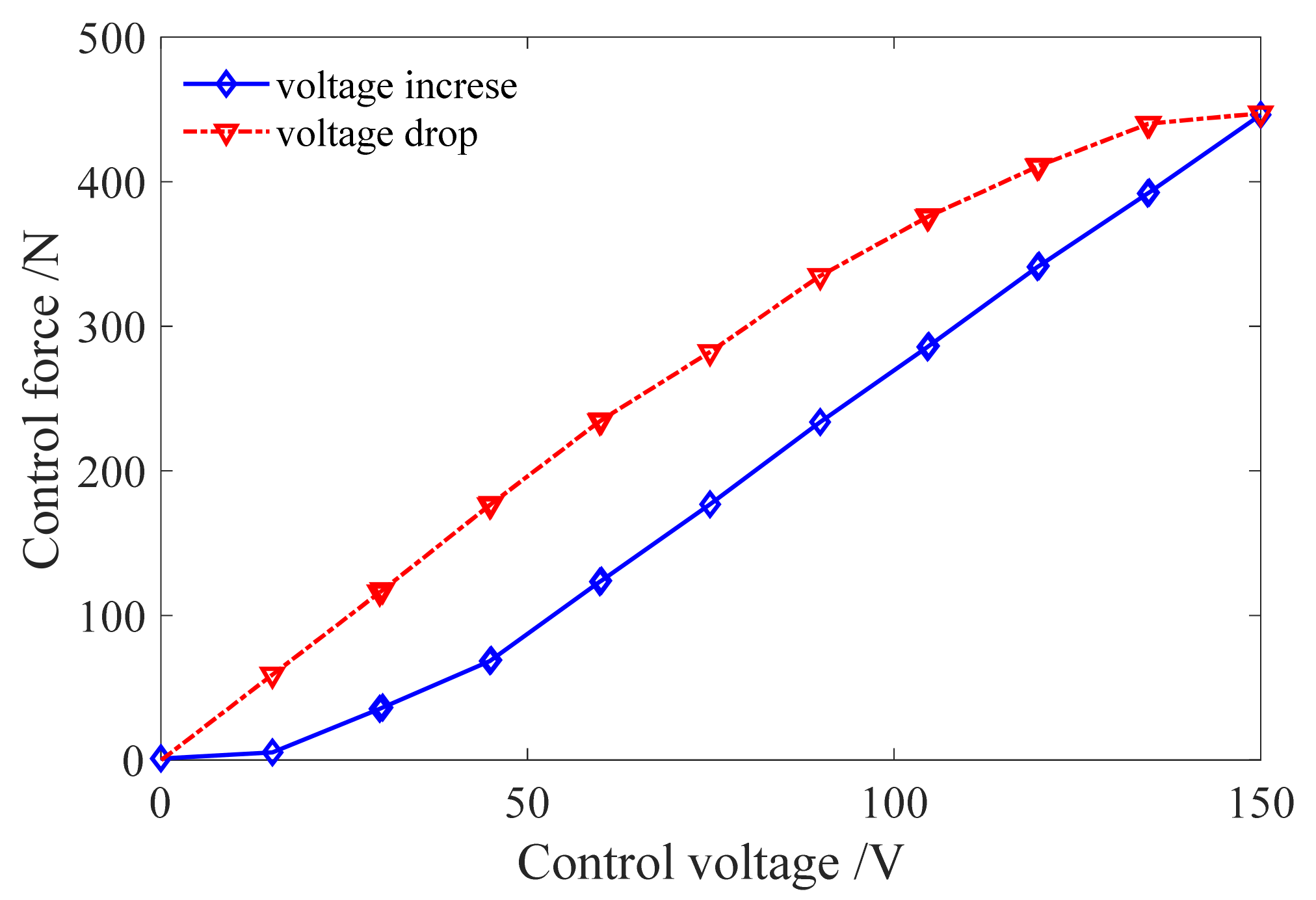
2.2. Analysis of Vibration Reduction Test Results of the Smart Spring

The response of the transition under different control voltages is shown in Figure 5. The card shows that when the driving voltage was activated, the peak value of the axial acceleration exceeding the critical acceleration was reduced, and the vibration peak value was reduced with the increase of the driving voltage.
Figure 6 shows the relationship between the peak acceleration of the central axis of each control voltage and the control voltage. It can be seen from the figure that the maximum damping rate of the shaft vibration peak value was 44.2%, which proves that the damping effect of the smart spring support was good.

3. Establishment of the Dynamic Model of Three-Support Shafting

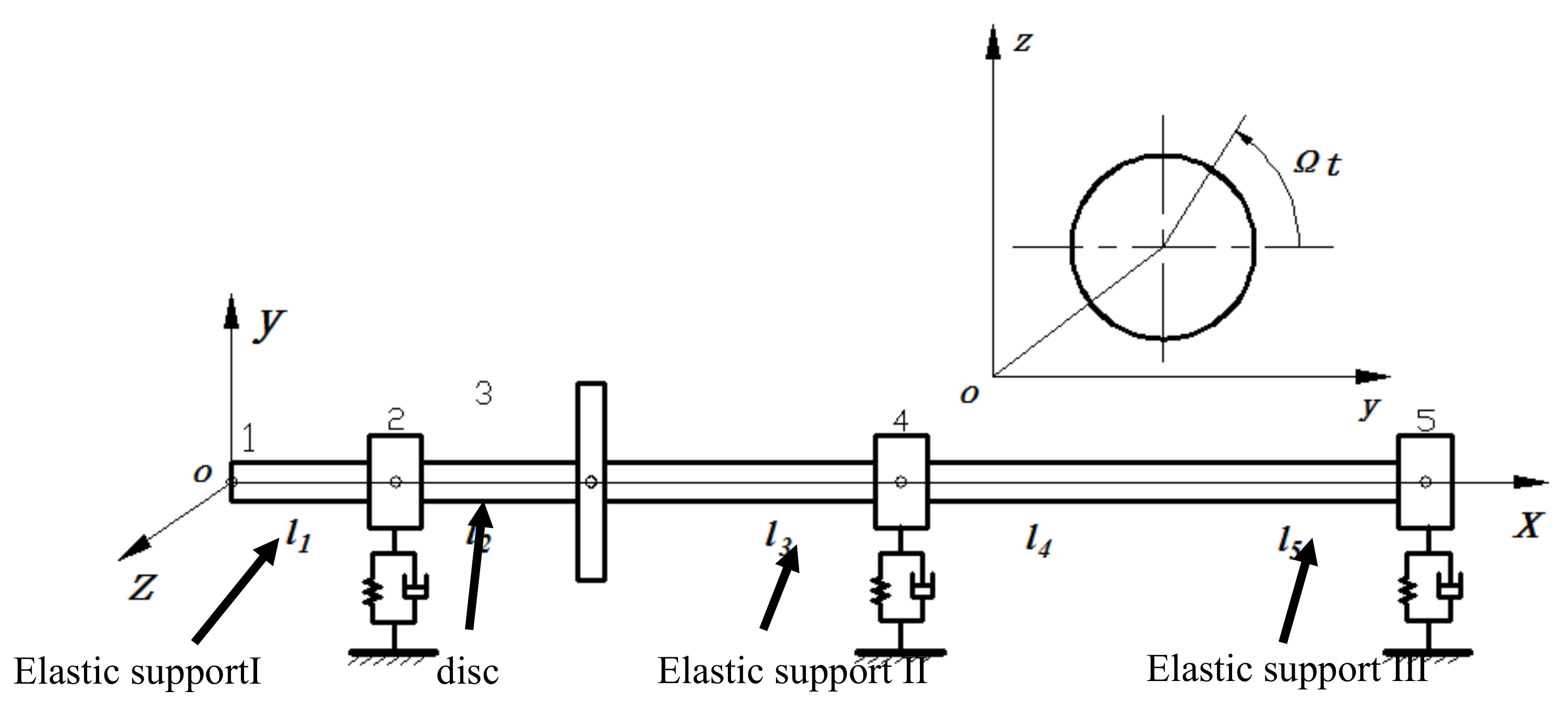
3.1. Dynamic Model Analysis of the Rotor Shaft System

A smart spring is a kind of elastic support with variable stiffness, damping and mass. Combined with the vibration reduction principle of smart springs, the smart spring is regarded as variable support II, and the influence of smart spring support parameters on the transcritical vibration characteristics of shafting was studied. The rotor system studied in this paper was a typical rotor–bearing system, which was composed of a rigid disk, an elastic shaft segment, a coupling and a bearing pedestal. Based on the finite element method, the rotor system was discretized into the disk, shaft segment and bearing pedestal. In the discrete process, the influence of the coupling on the bending vibration of the shafting was not considered. The two shafts were regarded as a single smooth shaft. The dynamic model of the shaft system was obtained by coupling. The structural units of the shafting were connected by nodes. These nodes were selected at the center of the disc and the center of the journal, and they were numbered sequentially, as shown in Figure 7.
The model hypotheses were as follows: (1) The model only considered the bending vibration of the shafting, and did not consider the torsional vibration; (2) the elastic shaft segment was equivalent to the Rayleigh beam axis model, which considered the gyroscopic effect and the moment of inertia; (3) the bearing support was simplified as a generalized force model with elasticity and damping; and (4) the axial section and support had circumferential symmetry.
There were three bearing supports and a rigid turntable distributed on the shafting. The stiffness and damping of the bearing in the y and z directions are expressed by k b y i , c b y i and k b z i , c b z i , respectively (i = I, II, III). The rigid disk was made of the same material as the shafting. The position of the axis can be expressed by the coordinates of the y and z axes, the deflection angle of the coordinate plane of xoy and xoz sections ( θ y , θ z ), and the self-rotation angle ϕ . When the shafting rotates at an equal angular velocity Ω , then ϕ = Ω t . Therefore, the displacement of any section of the shafting can be expressed as follows:
u 1 = y θ z u 2 = z θ y

3.2. Derivation of Motion Equation of the Three-Support Shafting

The second kind of Lagrange equation is used to derive the motion differential equations of each element:
d d t T q ˙ j T q j + V q j = Q j       j = 1 , 2 , N
where T is the kinetic energy of the system, V is the potential energy of the system, qj is the generalized coordinate of the system, Qj is the generalized force on the system and N is the number of degrees of freedom of the system.
Suppose generalized coordinates are represented as
q 1 = y ,   q 2 = z ,   q 3 = θ y ,   q 4 = θ z
If the mass, diameter and polar moment of inertia of a rigid disk are m , J d and J p , then the motion equation of the disk is
M d u ¨ 1 d + Ω J d u ˙ 2 d = Q 1 d M d u ¨ 2 d + Ω J d u ˙ 1 d = Q 2 d
where M d is the mass matrix of the disk, Q 1 d and Q 2 d are the generalized forces of the vibration response along the y-axis and z-axis and, supposing G d = Ω J d , then G d is the rotation matrix.
Assuming that the disk has a small eccentricity ( e y 0 , e z 0 ) and the influence of eccentricity on the moment of inertia is ignored, then the unbalanced force included in the generalized force can be approximately expressed as
Q 1 d u = m Ω 2 e y 0 0 cos Ω t + e z 0 0 sin Ω t Q 2 d u = m Ω 2 e z 0 0 cos Ω t + e y 0 0 sin Ω t
The equation of the motion of the elastic shaft segment element is as follows:
M x u ¨ 1 x + Ω J x u ˙ 2 x + K x u 1 x = Q 1 x M x u ¨ 2 x Ω J x u ˙ 1 x + K x u 2 x = Q 2 x
where M x = M x T + M x R , M x T is the moving inertia matrix of the element, M x R is the rotational inertia matrix of the element, K x is the stiffness matrix, and Q 1 x and Q 2 x are generalized force vectors, including the forces and moments of inertia of disks or adjacent elements connected at the nodes.
Assuming that the coordinates of the bearing support center are y b and z b and the node number corresponding to the journal center is s j , then the coordinates of the journal center are y x j and z x j . Assuming that the bearing support center coincides with the journal center, the motion equation of the bearing support is as follows:
M b 0 0 M b y ¨ x ( j ) z ¨ x ( j ) + c y y c y z c z y c z z y ˙ x ( j ) z ˙ x ( j ) + k y y k y z k z y k z z y x ( j ) z x ( j ) = 0
The generalized force acting on the journal node by the bearing support is
Q 1 d b Q 2 d b = M b 0 0 M b y ¨ x ( j ) z ¨ x ( j ) c y y c y z c z y c z z y ˙ x ( j ) z ˙ x ( j ) k y y k y z k z y k z z y x ( j ) z x ( j )
For a rotor system with nodes connected by shaft segments, the displacement vector of the system is
U 1 = y 1 , θ z 1 , y 2 , θ z 2 , , y N , θ z N T U 2 = z 1 , θ y 1 , z 2 , θ y 2 , , z N , θ y N T
From Equations (4) and (6), the motion equation of the rotor system can be obtained:
M 1 U ¨ 1 + Ω J 1 U ˙ 2 + K 1 U 1 = Q 1 M 1 U ¨ 2 Ω J 1 U ˙ 1 + K 1 U 2 = Q 2
Here, the mass matrix and rotation matrix are 2 N × 2 N diagonal matrices of order, the stiffness matrix is a 2 N × 2 N symmetric, sparse, banded matrix of order, and the half bandwidth is 4.
For the mass matrix and rotation matrix, the M 1 and J 1 matrices of the whole were still diagonal matrices after synthesis:
M 1 = ρ π r 4 2 l 1 1 4 l 1 r 2 ( l 1 + l 2 ) 1 4 l 1 + l 2 r 2 ( l 2 + l 3 ) + 2 ρ π r 2 m 1 4 l 2 + l 3 r 2 + 2 ρ π r 2 J d ( l 3 + l 4 ) 1 4 l 3 + l 4 r 2 l 4 1 4 l 4 r 2
J 1 = ρ π r 4 4 0 l 1 0 l 1 + l 2 0 l 2 + l 3 + 4 ρ π r 4 J p 0 l 3 + l 4 0 l 4
In the process of forming the above matrices, the influence of support was not considered, and the support could be reflected by the generalized force. The overall stiffness matrix K 1 is still a symmetric sparse banded matrix with a half bandwidth of 4:
K 1 = E I × 12 l 1 3 6 l 1 2 12 l 1 3 6 l 1 2 6 l 1 2 4 l 1 6 l 1 2 2 l 1 12 l 1 3 6 l 1 2 12 l 1 3 + 12 l 2 3 + k b 1 E I 6 l 1 2 + 6 l 2 2 12 l 2 3 6 l 2 2 6 l 1 2 2 l 1 6 l 1 2 + 6 l 2 2 4 l 1 + 4 l 2 6 l 2 2 2 l 2 12 l 2 3 6 l 2 2 12 l 2 3 + 12 l 3 3 6 l 2 2 + 6 l 3 2 12 l 3 3 6 l 3 2 6 l 2 2 2 l 2 6 l 2 2 + 6 l 3 2 4 l 2 + 4 l 3 6 l 3 2 2 l 3 12 l 3 3 6 l 3 2 12 l 3 3 + 12 l 4 3 + k b 2 E I 6 l 3 2 + 6 l 4 2 12 l 4 3 6 l 4 2 6 l 3 2 2 l 3 6 l 3 2 + 6 l 4 2 4 l 3 + 4 l 4 6 l 4 2 2 l 4 12 l 4 3 6 l 4 2 12 l 4 3 + k b 3 E I 6 l 4 2 6 l 4 2 2 l 4 6 l 4 2 4 l 4
For a bearing support with a rubber ring, the generalized force acting on the journal is shown in Equation (8). Since there is damping in the rubber ring, the force at the support has a coupling term, so Equation (10) should be rewritten as follows:
M 1 + M b 0 0 M 1 + M b U ¨ 1 U ¨ 2 + c 11 c 12 + G 1 c 21 G 1 c 22 U ˙ 1 U ˙ 2 + k 11 + K 1 k 12 k 21 k 22 + K 1 U 1 U 2 = Q 1 Q 2
where G 1 = Ω J 1 , G 1 is the rotation matrix.
Assume a set which can be expressed as
U = U 1 U 2 ,   M = M 1 + M b 0 0 M 1 + M b ,   C = c 11 c 12 + G 1 c 21 G 1 c 22 ,   K = k 11 + K 1 k 12 k 21 k 22 + K 1 ,   Q = Q 1 Q 2
In this case, Equation (14) can be written as
M U ¨ + Ω J U ˙ + K U = Q
Let us say we rearrange the coordinates so that
U ¯ = y 1 , θ z 1 , z 1 , θ y 1 , y 2 , θ z 2 , z 2 , θ y 2 , , y N , θ z N , z N , θ y N T
The motion equation after coordinate rearrangement still has the form of Equation (15), but it is a sparse matrix with a half bandwidth of 8.
The internal forces of each element in the shafting and the reaction forces of the supports have been eliminated in the process of equation synthesis such that only the generalized forces of unbalanced excitation were included. Here, only the unbalanced excitation at the disk was considered, and the generalized force is shown in Equation (5).

4. Analysis of the Influence of Support Parameters on the Steady-State Unbalance Response of Shafting

4.1. Solution of the Critical Speed of Three-Support Shafting

According to the differential equation of the rotor system, the whirling frequency ω could be obtained by the homogeneous solution of the differential equation. According to the different rotation speeds, the critical speed could be obtained by the Campbell diagram. The parameters of the three-support shafting system are shown in Table 2.
If t = 0, then
U ( 0 ) = 0 U ˙ ( 0 ) = 0
The generalized force of the system is generated by the eccentricity at the disk, and its eccentricity is ey0 = ez0 = e0. The steady-state differential equation of the system is
M 1 + M b U ¨ 1 + C 1 U ˙ 1 + G 1 U ˙ 2 + K 1 U 1 = Q 1 M 1 + M b U ¨ 2 + C 1 U ˙ 2 + G 1 U ˙ 1 + K 1 U 2 = Q 2
where C 1 = d i a g ( 0 , 0 , 0 , 0 , c 3 , 0 , c b 2 , 0 , 0 , 0 ) , c 3 is the bending damping at the disk and c b 2 is the damping of the rubber damping ring at support II. We can divide the first line of Equation (17) into the following:
a 1 l 1 y ¨ 1 + a 3 12 l 1 3 y 1 + 6 l 1 2 θ z 1 12 l 1 3 y 2 + 6 l 1 2 θ z 2 = 0 1 4 a 1 l 1 r 2 θ ¨ z 1 Ω a 2 l 1 θ ˙ y 1 + a 3 6 l 1 2 y 1 + 4 l 1 θ z 1 6 l 1 2 y 2 + 2 l 1 θ z 2 = 0 a 1 l 1 + l 2 + m b 1 y ¨ 2 + a 3 12 l 1 3 y 1 6 l 1 2 θ z 1 + ( 12 l 1 3 + 12 l 2 3 + k b 1 a 3 ) y 2 + ( 6 l 2 2 6 l 1 2 ) θ z 2 12 l 2 3 y 3 + 6 l 2 2 θ z 3 = 0 1 4 a 1 ( l 1 + l 2 ) r 2 θ ¨ z 2 Ω a 2 ( l 1 + l 2 ) θ ˙ y 2 + a 3 6 l 1 2 y 1 + 2 l 1 θ z 1 + ( 6 l 2 2 6 l 1 2 ) y 2 + ( 4 l 1 + 4 l 2 ) θ z 2 6 l 2 2 y 3 + 2 l 1 θ z 3 = 0 a 1 ( l 2 + l 3 ) + m y ¨ 3 + c 3 y ˙ 3 + a 3 12 l 2 3 y 2 6 l 2 2 θ z 2 + ( 12 l 2 3 + 12 l 3 3 ) y 3 + ( 6 l 3 2 6 l 2 2 ) θ z 3 12 l 3 3 y 4 + 6 l 3 2 θ z 4 = m Ω 2 ( e 0 cos Ω t e 0 sin Ω t ) ( 1 4 a 1 ( l 2 + l 3 ) r 2 + J d ) θ ¨ z 3 Ω a 2 ( l 2 + l 3 ) θ ˙ y 3 + a 3 6 l 2 2 y 2 + 2 l 2 θ z 2 + ( 6 l 3 2 6 l 2 2 ) y 3 + ( 4 l 2 + 4 l 3 ) θ z 3 6 l 3 2 y 4 + 2 l 3 θ z 4 = 0 a 1 ( l 3 + l 4 ) + m b 2 y ¨ 4 + c 4 y ˙ 4 + a 3 12 l 3 3 y 3 6 l 3 2 θ z 3 + ( 12 l 3 3 + 12 l 4 3 + k b 2 a 3 ) y 4 + ( 6 l 4 2 6 l 3 2 ) θ z 4 12 l 4 3 y 5 + 6 l 4 2 θ z 5 = 0 1 4 a 1 ( l 3 + l 4 ) r 2 θ ¨ z 4 Ω a 2 ( l 3 + l 4 ) θ ˙ y 4 + a 3 6 l 3 2 y 3 + 2 l 3 θ z 3 + ( 6 l 4 2 6 l 3 2 ) y 4 + ( 4 l 3 + 4 l 4 ) θ z 4 6 l 4 2 y 5 + 2 l 4 θ z 5 = 0 ( a 1 l 4 + m b 3 ) y ¨ 5 + a 3 12 l 4 3 y 4 6 l 4 2 θ z 4 + ( 12 l 4 3 + k b 3 a 3 ) y 5 6 l 4 2 θ z 5 = 0 1 4 a 1 l 4 r 2 θ ¨ z 5 Ω a 2 l 4 θ ˙ y 5 + a 3 6 l 4 2 y 4 + 2 l 4 θ z 4 6 l 4 2 y 5 + 4 l 4 θ z 5 = 0
where a 1 = ρ π r 2 2 , a 2 = ρ π r 4 4 and a 3 = E I . Suppose that
y 1 , θ z 1 , y 2 , θ z 2 , y 3 , θ z 3 , y 4 , θ z 4 , y 5 , θ z 5 = y 10 , θ 10 , y 20 , θ 20 , y 30 , θ 30 , y 40 , θ 40 , y 50 , θ 50 cos ( ω t + α )
θ y 1 , θ y 2 , θ y 3 , θ y 4 , θ y 5 = θ 10 , θ 20 , θ 30 , θ 40 , θ 50 sin ( ω t + α )
Equation (18) is the motion equation of the system. The determinant could be used to obtain the frequency equation of the system. Through the frequency equation, 10 forward and 10 reverse whirl frequencies could be obtained. According to different rotor speeds, the whirling speeds could be calculated. As shown in Table 3, the relationship between the first two orders of whirl frequencies and the rotational speed is given.
According to the data in Table 2, the relation curve between the rotation angle velocity and the vortex frequency was drawn, as shown in Figure 8. According to Figure 8, the critical angular velocity and critical speed of the rotor shafting are shown in Table 4. Under the same parameters, the simulation results showed that the critical speeds of the first two stages of the positive vortex were n F c 1 = 3949.1 r / min 1 and n F c 2 = 6396.4 r / min 1 .

4.2. Analysis of the Influence of Support Parameters on Shafting Response

Based on the simulation platform, the vibration response of the shaft system could be obtained by solving the differential equation of the rotor system. The modules provided in Simulink were used to build the block diagram of the numerical model. In the process of establishing the numerical model of three-support shafting, the From and Goto modules in signal routing were used to avoid the connection problem of complex block diagrams. When building the model, we only needed to build a separate solving model according to a certain determinant, and each solving model was connected by From and Goto. In Section 4.1, the first order critical speed of three-support shafting was obtained. In this paper, the stiffness, damping and mass of support II were changed when the rotor system was at transcritical speed and after the critical speed under the eccentric load of the shaft system. The dynamic response of the rotor system under different support parameters was analyzed. The specific simulation parameter values are shown in Table 5.
(1) Analysis of the influence of stiffness on the dynamic response of shafting
The influence of the support stiffness of the rotor system on the dynamic response of the shafting at transcritical and subcritical speeds is shown in Figure 9 and Figure 10. Figure 9 shows the vibration response of the disc and the support when the rotor shaft system is in steady-state operation with Ω = 400 rad/s and the different stiffness values of the smart spring support. It can be seen from Figure 9 that, with the increase of the smart spring support stiffness, the steady-state vibration response of the disc and the support could be effectively suppressed. The stiffness increased from 3.8 × 10⁵ N·m−1 to 3.8 × 10⁸ N·m−1, and the peak amplitude of the disc decreased by 45.45%. As can be seen from Figure 10a, when the rotor shaft system operated stably at Ω = 600 rad/s, the change of vibration amplitude at the disc with the smart spring support stiffness was not obvious, but the steady-state response was the minimum when the smart spring support stiffness was Ω = 600 rad/s. It can be seen from Figure 10b that the steady vibration response of the smart spring was smaller than that of 3.8 × 10⁶ N·m−1 when the support stiffness was 3.8 × 10⁵ N·m−1. Compared with Figure 9 and Figure 10, it can be seen that when the vibration response under a steady state was large, the vibration response of the disc and the support decreased with the increase of the support stiffness of the smart spring. When the vibration response was small in the steady state, the change of the support stiffness of the smart spring had no obvious effect on the vibration at the disc.
(2) Influence of damping on the dynamic response of shafting
The influence of the smart spring support damping on the dynamic response of the rotor system after and over the critical speed is shown in Figure 11 and Figure 12. Figure 11 and Figure 12 show the radial vibration response curves of the disc and support along the y-axis direction when the rotor shaft system was subjected to eccentric excitation as the smart spring support took different damping values. It can be seen from the figure that when the shafting was in steady-state operation (that is, the vibration peak value of the shafting was small), the damping of the smart spring support had no obvious effect on the vibration of the shafting.
(3) Influence analysis of bearing mass on the dynamic response of shafting
The influence of the supporting mass of the rotor system on the dynamic response of the shafting at critical speed and subcritical speeds is shown in Figure 13 and Figure 14. Figure 13 and Figure 14 show the steady-state response curves of the disc and support of the smart spring support under different masses and eccentric excitations of the rotor shaft system. When the shafting was in the accelerated critical state, it can be seen from Figure 13 that the smaller the mass of the smart spring support was, the smaller the vibration of the shafting was. The peak amplitude at the support increased by 89.4% by the increasing of support’s mass from 4 kg to 12 kg. It can be seen from Figure 14 that when the vibration response was small, the change of the mass of the smart spring support could change the response amplitude at the disc, but the influence on the vibration amplitude was not obvious.
Figure 15 shows the influence trend of the stiffness, damping and mass of the smart spring support on the dynamic response of the rotor shaft system when Ω = 400 rad/s. It can be seen from the figure that when the vibration response was large, with the increase of the stiffness of the smart spring support, the vibration response of the disc and the support decreased, but the damping of the smart spring support had no obvious influence on the steady-state vibration of the shafting. When the vibration response was large, the smaller the mass of the smart spring support, the smaller the vibration of the shafting.

5. Conclusions

In this paper, the vibration reduction performance test of the smart spring was carried out to verify the vibration reduction effect of the smart spring. The motion equation of three-support shafting was established by the finite element method, and the influence of smart spring support parameters on the dynamic response characteristics of shafting in a cross-critical state and a steady state was analyzed. By studying the dynamic characteristics of three-support shafting, the following conclusions were obtained:
(1)
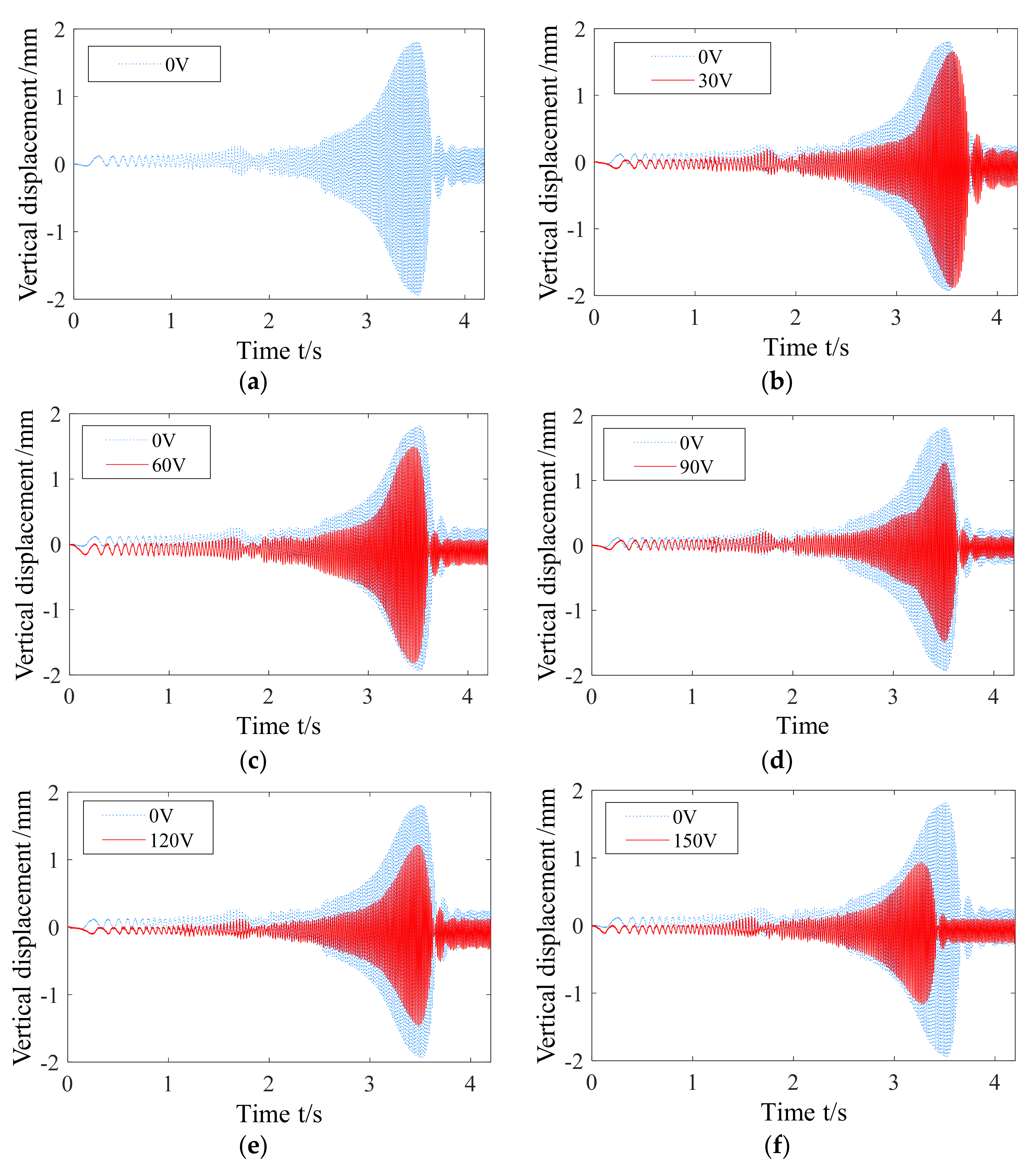
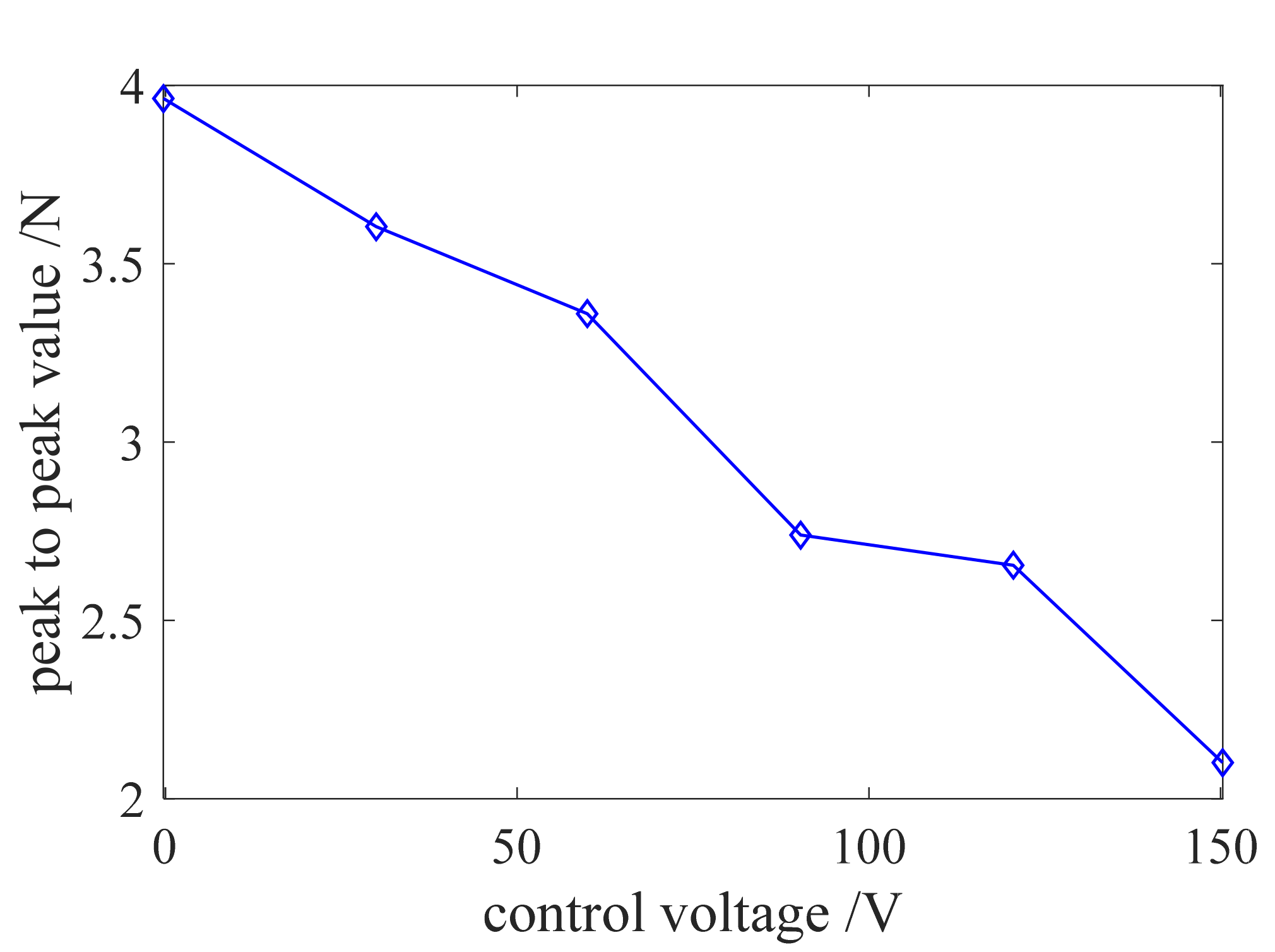
On the basis of the smart spring test results, it was confirmed that when the maximum control voltage was 150 V, the maximum vibration reduction rate reached 44.2%, which verified that the smart spring support had a good control effect on the lateral bending vibration of the three-support shaft under the state of acceleration toward crossing critical speed.
(2)
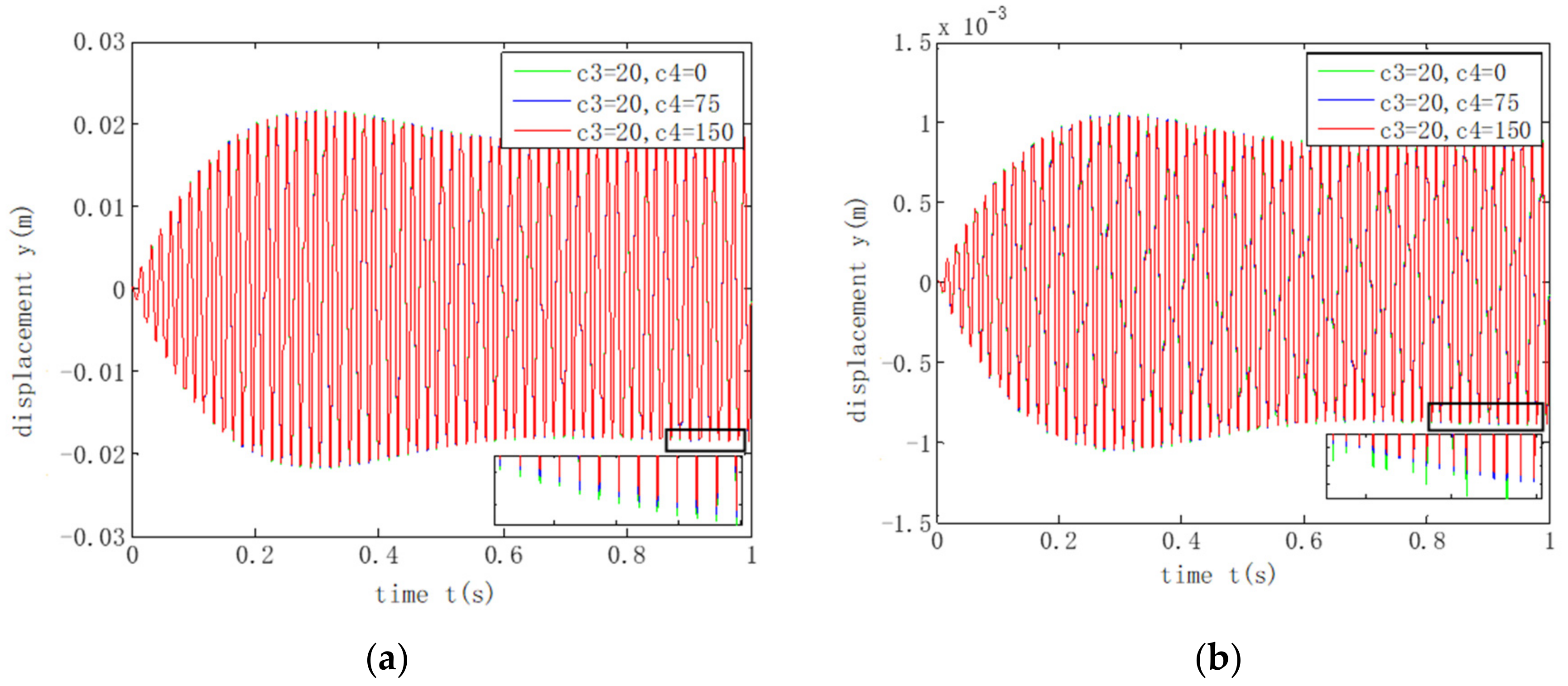
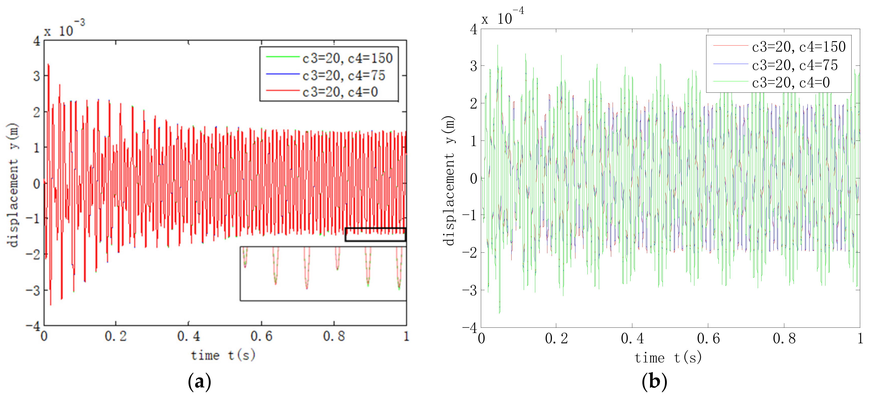
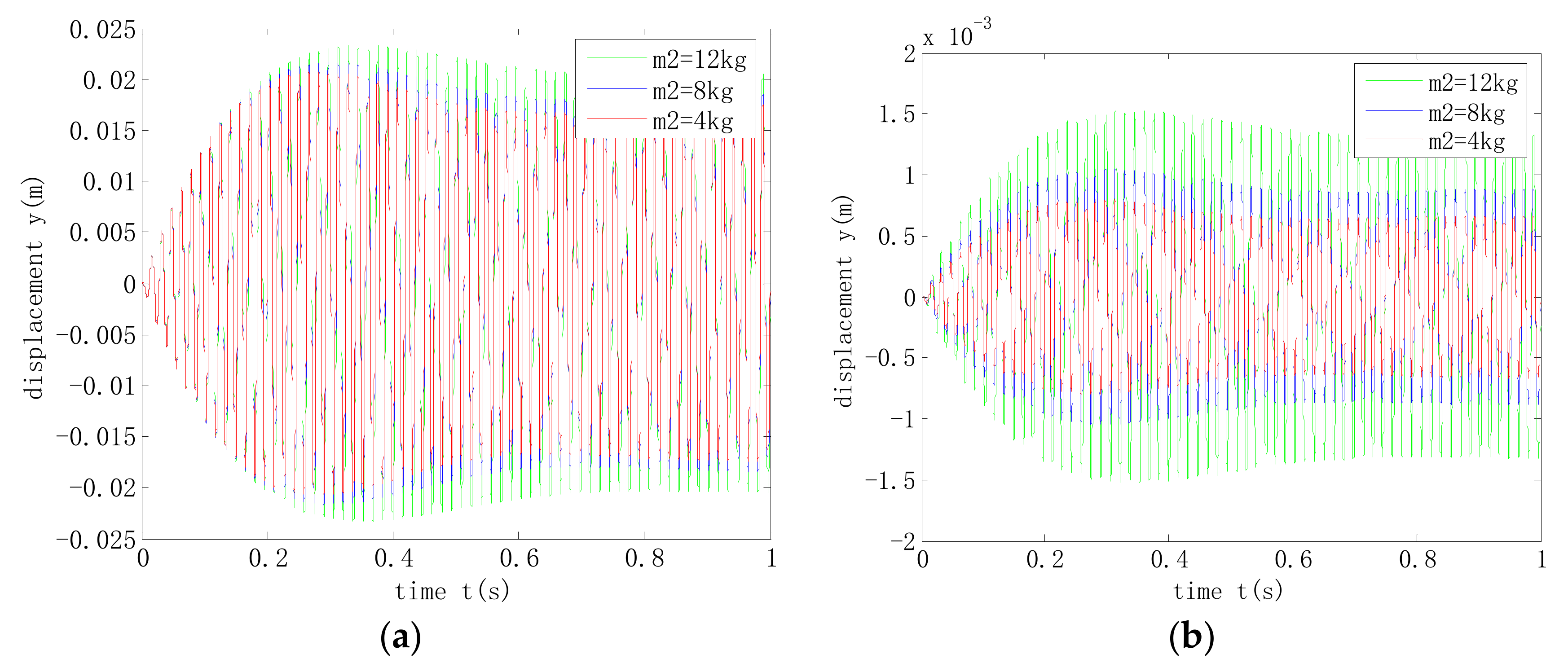
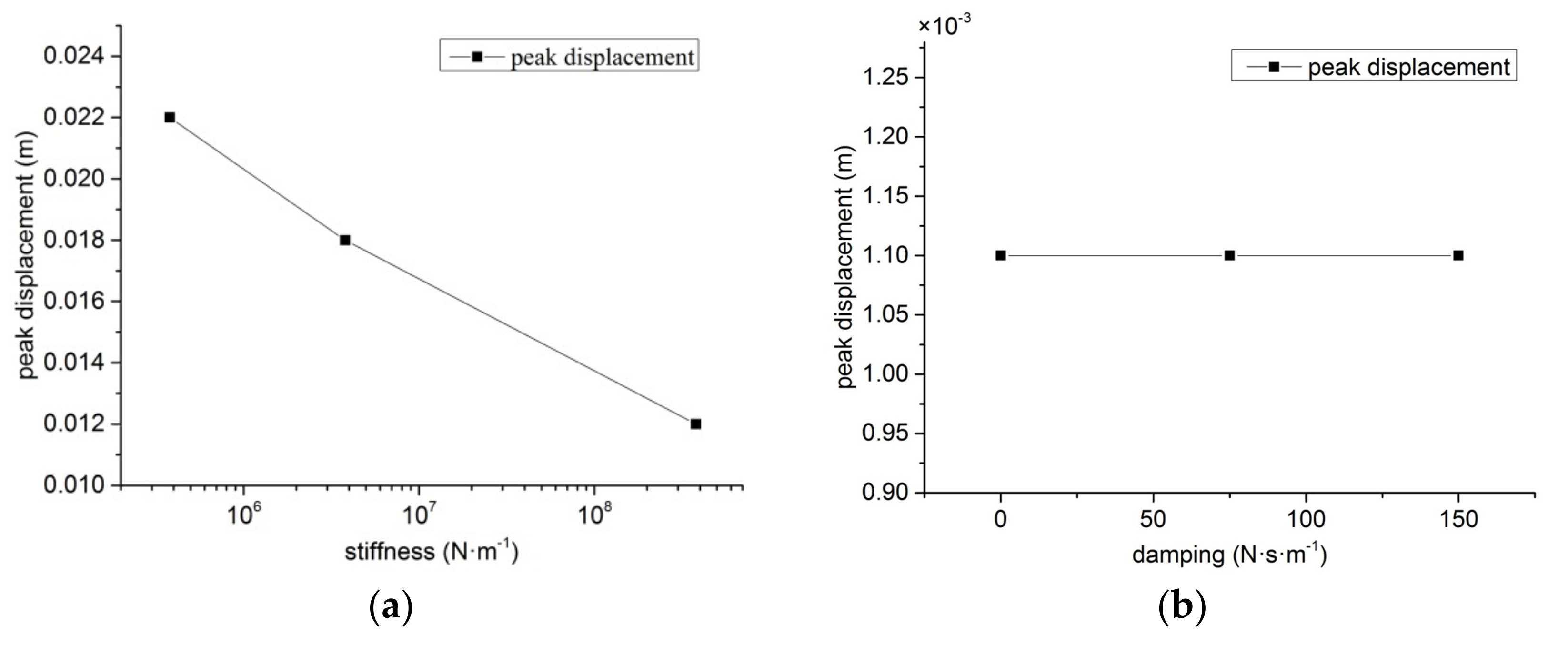
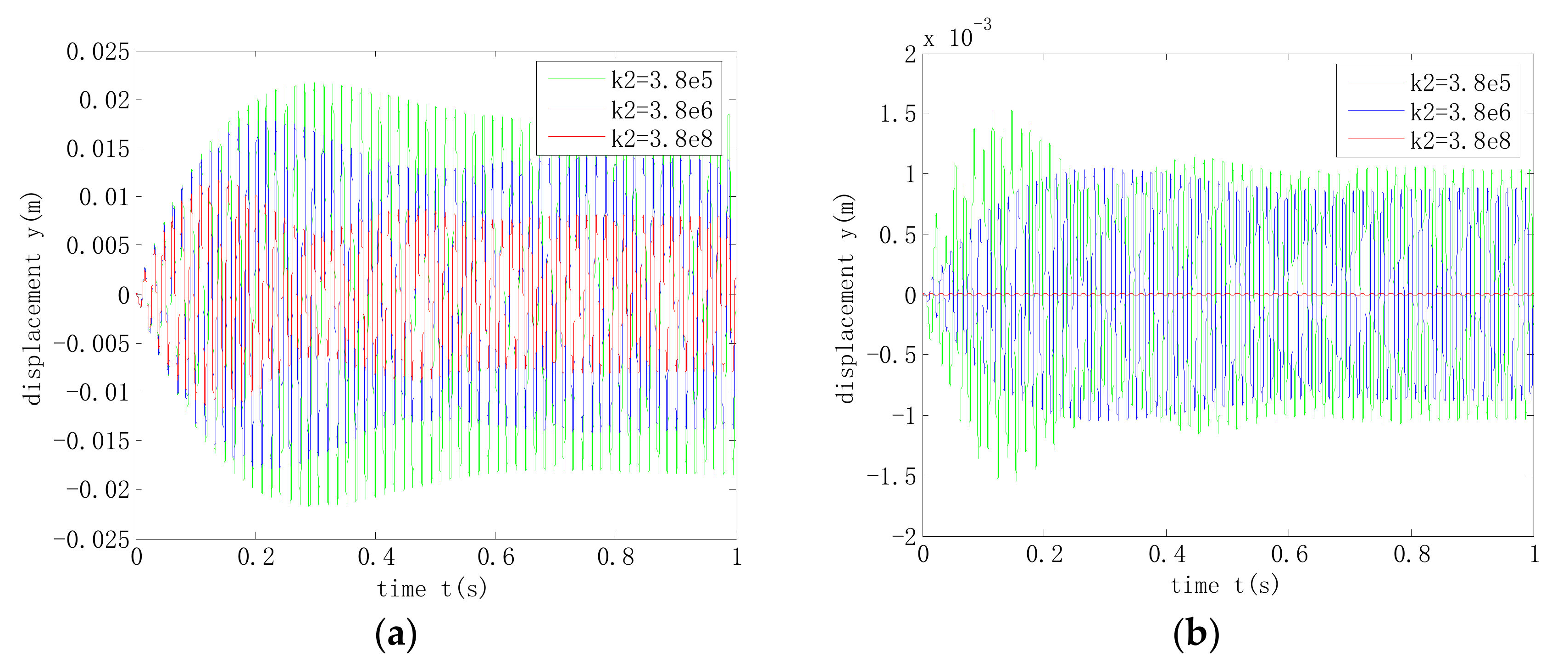
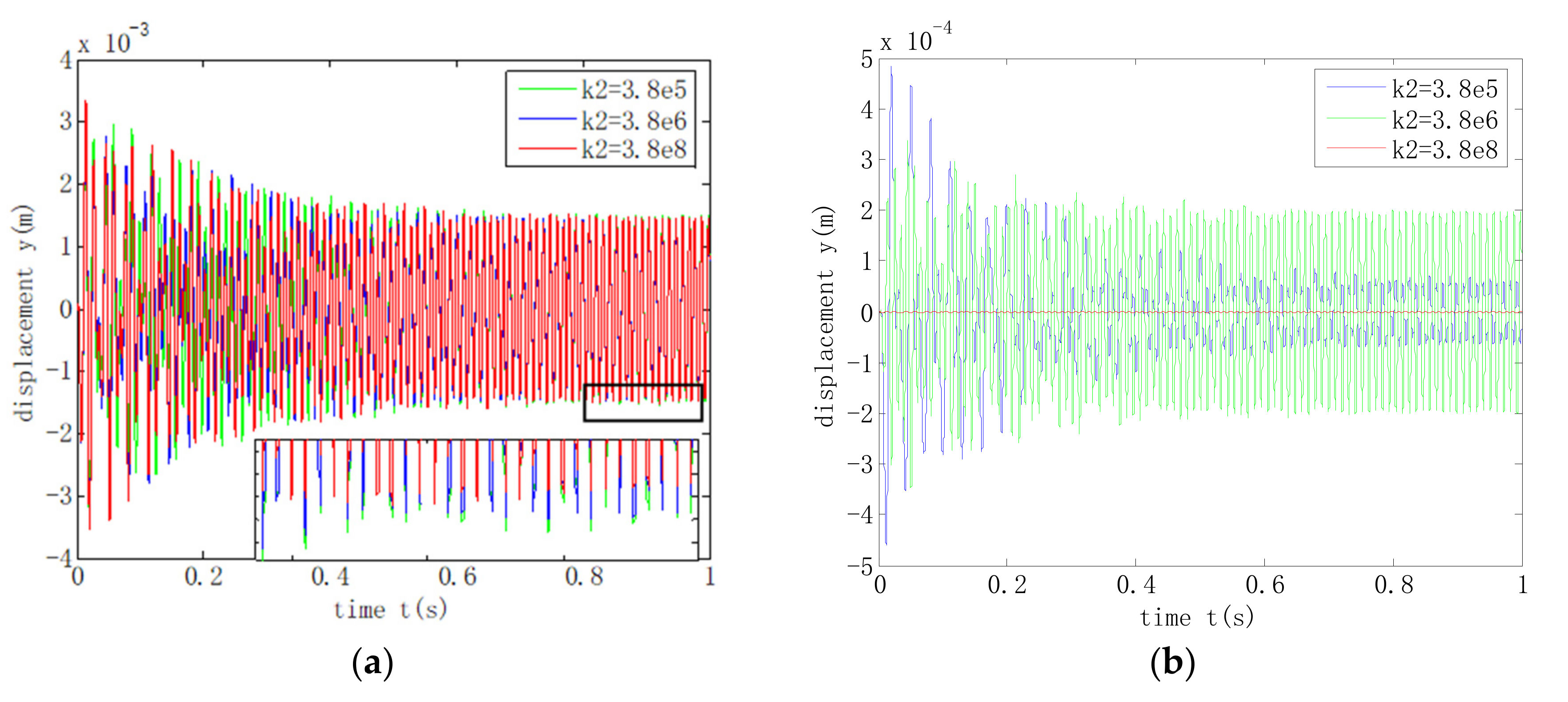
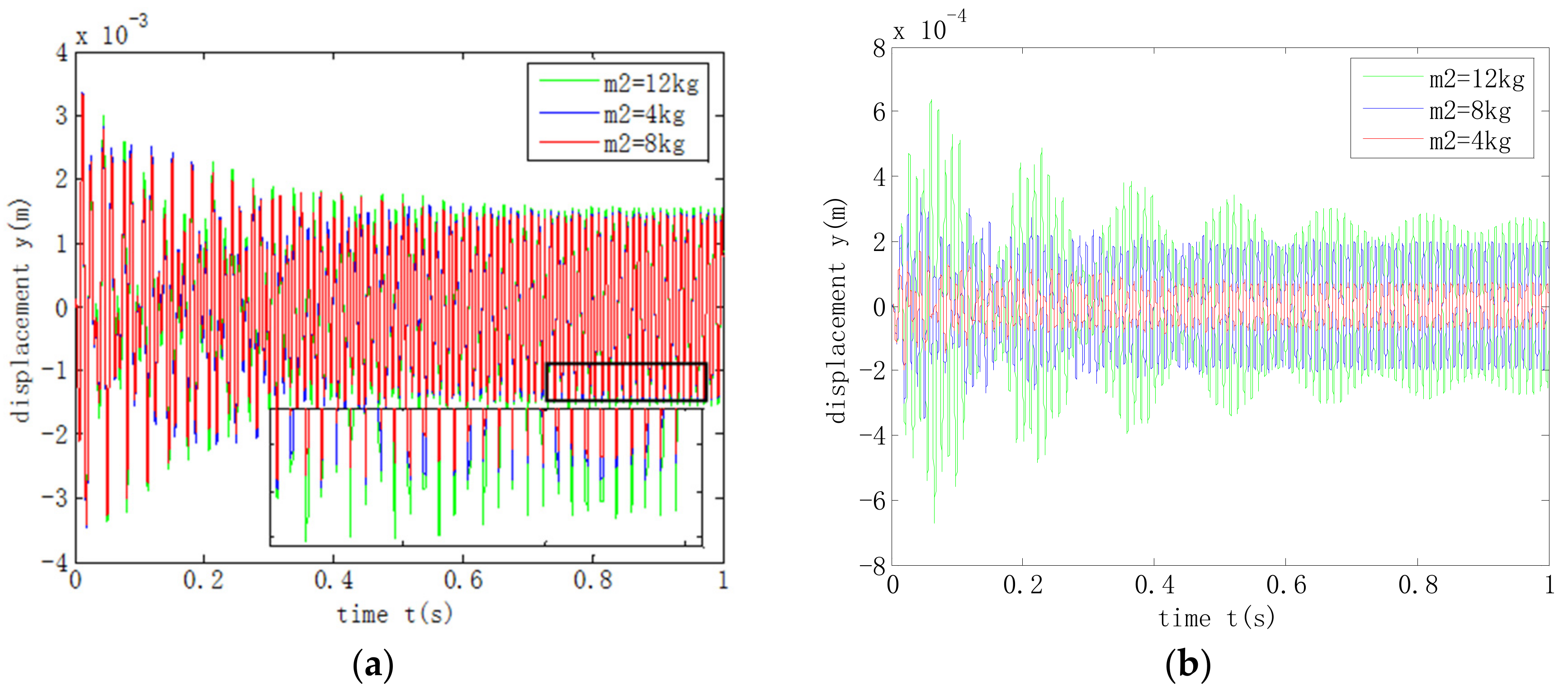
During acceleration over the critical state of the shafting, the increase of the stiffness of the smart spring support could effectively reduce the amplitude of the three-support shafting. At this time, the change of damping at the smart spring support has no obvious effect on the vibration response of the system. In addition, the smaller the mass of the smart spring support, the smaller the vibration response of the system and the greater the impact on the support vibration.

Author Contributions

Conceptualization, M.-m.L.; methodology, M.-m.L.; software, M.-m.L. and L.-l.M.; validation, M.-m.L., L.-l.M. and C.-g.W.; data curation, Z.L.; writing—Original draft preparation, L.-l.M. and C.-g.W.; writing—Review and editing, M.-m.L.; supervision, C.-g.W. and Z.L.; project administration, R.-p.Z.; funding acquisition, R.-p.Z. and M.-m.L. All authors have read and agreed to the published version of the manuscript.

Funding

This work was supported by the National Natural Science Foundation of China (Grant No. 51775265) and the National Key Laboratory of Science and Technology on Helicopter Transmission (Nanjing University of Aeronautics and Astronautics) (Grant No. HTL-A-19G09).

Conflicts of Interest

The authors declare no conflict of interest.

References

  1. Wenzhong, Q.; Jincai, S.; Yang, Q. Active control of vibration using a fuzzy control method. J. Sound Vib. 2004, 275, 917–930. [Google Scholar] [CrossRef]
  2. De, N. Research on Design Method of Smart Spring Damping System and Its Application in the Drive Shaft System. Ph.D. Thesis, Nanjing University of Aeronautics and Astronautics, Nanjing, China, 2015. [Google Scholar]
  3. Nitzsche, F.; Feszty, D.; Grappasonni, C.; Coppotelli, G. Whirl-tower Open-loop Experiments and Simulations with an Adaptive Pitch Link Device for Helicopter Rotor Vibration. In Proceedings of the AIAA/ASME/ASCE/AHS/ASC Structures, Structural Dynamics and Materials Conference, Boston, MA, USA, 8–11 April 2013; pp. 1–13. [Google Scholar]
  4. Afagh, F.; Nitzsche, F.; Morozova, N. Dynamic modelling and stability of hingeless helicopter blades with a smart spring. Aeronaut. J. 2004, 108, 369–377. [Google Scholar] [CrossRef]
  5. Coppotelli, G.; Marzocca, P.; Ulker, F.D.; Campbell, J.; Nitzsche, F. Experimental Investigation on Modal Signature of Smart Spring/Helicopter Blade System. J. Aircr. 2008, 45, 1373–1380. [Google Scholar] [CrossRef]
  6. Aldemir, A.C., Jr. Vibration attenuation in rotating machines using smart spring mechanism. Math. Probl. Eng. 2011, 1–14. [Google Scholar]
  7. Li, M..; Ma, L.L.; Wu, C.G.; Zhu, R.P. Study on the vibration active control of three-support shafting with smart spring while accelerating over the critical speed. Appl. Sci. 2020, 10, 6100. [Google Scholar] [CrossRef]
  8. Li, Q.-C.; Yu, Q.; Liu, W. Effect of supporting parameters on marine shaft vibration characteristics. Ship Sci. Technol. 2016, 38, 101–104. [Google Scholar]
  9. Li, H.-F.; Zhu, S.-J.; Liu, X.-W. Analysis of the effects of bearing stiffness on vibration transmission paths in ship propulsion shafting. Noise Vib. Control 2016, 36, 57–60. [Google Scholar]
  10. Li, X.; Zhu, H.; Yang, W.; Liu, L.; Yang, Z.R. Analysis of the influence of variable stiffness support on transverse vibration of ship shafting. China Ship. Repair. 2015, 28, 34–37. [Google Scholar]
  11. Van, T.N.; Dan, M.X. Analysis behavior of a rig shafting vibration set changes bearing parameters. Appl. Mech. Mater. 2013, 437, 98–101. [Google Scholar]
  12. Luo, J.-B.; Liu, Z.-H.; Shi, Y.; Xie, D.M.; Yu, X.G. The research on supporting stiffness of LP rotor of ultra-supercritical turbine. In Proceedings of the 2011 International Conference on Electrical and Control Engineering (ICECE), Yichang, China, 16–18 September 2011. [Google Scholar]
  13. Ma, J.; Dai, J.; Sun, B.-N.; Kou, X.-P.; Jing, J.-P. Supporting characteristics of bearings and their effects on dynamical behaviors of rotor system. Noise Vib. Control. 2011, 31, 22–26. [Google Scholar]
  14. Kumar, C.; Sarangi, S. Dynamic response of an unbalanced rigid rotor bearing system with a nonlinear hydrodynamic force. J. Comput. Nonlinear Dyn. 2018, 13, 090909-6. [Google Scholar] [CrossRef]
  15. Wang, B. Effect of bearing stiffness on ship shafting system vibration performance. J. Qiqihar Univ. 2009, 25, 55–60. [Google Scholar]
  16. Sun, B.-N.; Xie, F.; Jing, J.-P. Effects of bearings support characteristics on shaft stability. Noise Vib. Control 2012, 32, 137–140. [Google Scholar]
  17. Xu, J.-W.; Li, W.-B. Analysis on static and dynamic characteristics of electric spindle based on ANSYS. Mach. Des. Manuf. 2015, 09, 11–28. [Google Scholar]
  18. Su, C.-J.; Li, Z.; Xu, Y.-R. Analysis of vibration characteristics and response of the working ship propulsion shafting. Ship Ocean Eng. 2016, 45, 137–140. [Google Scholar]
  19. Zhang, X. Influence of equivalent supporting point location in stern bearing on shaft whirling vibration. Ship Ocean Eng. 2012, 41, 46–49. [Google Scholar]
  20. Jauhari, K. Vibration reduction of spindle-bearing system by design optimization. WSEAS Trans. Appl. Theor. Mech. 2018, 13, 85–91. [Google Scholar]
  21. Yücel, E.; Saruhan, H. Design optimization of rotor-bearing system considering critical speed using Taguchi method. Proc. Inst. Mech. Eng. Part E J. Process. Mech. Eng. 2016, 231, 138–146. [Google Scholar] [CrossRef]
Figure 1. Shafting test rig.
Applsci 10 07752 g001
Figure 2. Layout of the test data acquisition device.
Applsci 10 07752 g002
Figure 3. Principle sketch (a) and structure diagram (b) of the smart spring.
Applsci 10 07752 g003
Figure 4. Relationship between the control force and control voltage of the smart spring support.
Applsci 10 07752 g004
Figure 5. Acceleration over critical vibration response of shafting under different control voltages: (a) 0 V, (b) 30 V, (c) 60 V, (d) 90 V, (e) 120 V and (f) 150 V.
Applsci 10 07752 g005
Figure 6. Relationship between the peak value and control voltage of the shaft system over a critical vibration response.
Applsci 10 07752 g006
Figure 7. Dynamic model of the rotor shaft system.
Applsci 10 07752 g007
Figure 8. The relationship between rotation speed and whirl frequency.
Applsci 10 07752 g008
Figure 9. The vibration response of (a) the disk and (b) support II with different stiffnesses for Ω = 400 rad/s.
Applsci 10 07752 g009
Figure 10. The vibration response of (a) the disk and (b) support II with different stiffnesses for Ω = 600 rad/s.
Applsci 10 07752 g010
Figure 11. The vibration response of (a) the disk and (b) support II with different support II damping for Ω = 400 rad/s.
Applsci 10 07752 g011
Figure 12. The vibration response of (a) the disk and (b) support II with different support II damping for Ω = 600 rad/s.
Applsci 10 07752 g012
Figure 13. The vibration response of (a) the disk and (b) support II with different masses of support II at Ω = 400 rad/s.
Applsci 10 07752 g013
Figure 14. The vibration response of (a) the disk and (b) support II with different masses of support II at Ω = 600 rad/s.
Applsci 10 07752 g014
Figure 15. The vibration response of support II with different support stiffness (a), damping (b) and mass (c) at Ω = 400 rad/s.
Applsci 10 07752 g015aApplsci 10 07752 g015b
Table 1. Basic parameters of three-support shafting.
Parameter NameValue/UnitParameter NameValue/Unit
The density of the shaft ρ7850/(kg∙m−3)Elastic modulus E2 × 1011/Pa
Shaft radius r7.5/mmDisc radius R75/mm
Length of shaft l1120/mmDisc width b8/mm
Length of shaft l270/mmSupport stiffness kb1.7 × 105/(N∙m−1)
Length of shaft l380/mmSupport damping cb60/(N∙s∙m−1)
Length of shaft l4270/mmUnbalance magnitude e06.3 × 10−5/(kg∙m)
Length of shaft l3420/mmAuxiliary support stiffness ka6 × 105/(N∙m−1)
Table 2. Basic parameters of the three-support shaft system.
Parameter NameValue/Unit
The density of the shaft (ρ)7850/(kg∙m−3)
Elastic modulus (E)2 × 10¹¹/Pa
Disc radius (R)50/mm
Shaft radius (r)7/mm
Length of shaft (l1)198/mm
Length of shaft (l2)138/mm
Length of shaft (l3)322/mm
Length of shaft (l4)588/mm
Disc mass (m)1.05/kg
Support mass (mb1, mb2, mb3)8/kg
Stiffness of support I and III (kb1, kb3)2.89 × 10⁸/(N∙m−1)
Stiffness of support II (kb2)3.8 × 10⁶/(N∙m−1)
Support damping I and III (cb1, cb3)0
Support damping II (cb2)75/(N∙s∙m−1)
Angular speed (Ω)400/(rad/s)
Eccentricity (e0)1/mm
Table 3. The relationship between speed and whirl frequency.
Ω/Rad s−1First Positive Whirls
ωF1/rad s−1
Second Positive Whirls
ωF2/rad s−1
First Counter Whirls
ωB1/rad s−1
Second Counter Whirls
ωB2/rad s−1
0410.5673.1−410.5−673.1
200410.6673.1−410.4−673.1
400410.6673.1−410.4−673.1
600410.7673.1−410.3−673.1
800410.8673.1−410.2−673.1
Table 4. Critical angular velocity and critical speed.
Synchronous Positive WhirlSynchronous Counter Whirl
ωFc/rad·s−1nFc/r·min−1ωBc/rad·s−1nBc/r·min−1
410.63923−410.4−3921
673.16431−673.1−6431
Table 5. Different support parameters of the rotor shafting simulation.
SchemeStiffness/N m−1Damping/N s m−1Mass/kg
3.8e504
3.8e6758
3.8e815012
Publisher’s Note: MDPI stays neutral with regard to jurisdictional claims in published maps and institutional affiliations.

