1. Introduction
The change in the modern battlefields to local and asymmetric warfare has forced the armed forces of major nations to find solutions for expanding their abilities in responding to these changes [
1]. Since their existing capabilities are limited with respect to coping with current battlefields involving new and potential threats, the acquisition and deployment of new weapon systems are important to prepare for expected conflicts [
2]. This means that traditional approaches for the design of weapons need to be modified to prepare for unprecedented aspects of warfare. The solutions include the enhancement of existing weapon platforms or a revision of their designs [
3]. Designers need a comprehensive understanding of the potential battlefield environments for weapon system design; based on their understanding, they need to derive technical factors that enable functional requirements, while considering the interactions among these factors to design new weapons [
4]. Moreover, both the design and evaluation of weapons are important, and technical approaches are needed to support both aspects. One of the practical alternatives is to employ modeling and simulation (M&S) techniques, which can be utilized as tools to support the design of complex systems [
5], and which are also applied to the development of weapon systems. It provides opportunities to confirm the strengths and weaknesses of weapon systems during their development without actual tests. In particular, the techniques can be used to determine their ability to perform specific missions or to check shortfalls when encountering specific threats [
6]. Currently, M&S techniques are widely used for acquisition, training, analysis, test, and evaluation missions [
7]; the armed forces of major nations utilize M&S techniques to reduce the development cycle of weapon systems [
8]. The importance of M&S techniques will increase as the complexity of weapon systems grows [
5].
However, the application of M&S techniques to the weapon development process involves potential difficulties derived from similar studies. First, there is no simulation model that provides solutions for all problems of any specific field; hence, designers should design certain models for the specific purposes [
6]. Second, although a model of the same type is designed, its forms can be diverse according to the intention of designers; moreover, it is difficult and time consuming to perform modeling that satisfies every demand [
9,
10]. Third, the increase in the number of requirements can cause an increase in the number and relevance of constituents and increase the complexity of modeling [
4].
This paper aims to define efforts to handle these issues, and includes designing a reusable modeling method, intelligent modeling process, and simulation to test the model. Consequently, our proposed method has the following three benefits: (1) It provides a generalized structure and its parts for each weapon system to design the constituent modules, (2) it offers an automated modeling process that covers all design factors through an intelligent method such as case-based reasoning (CBR), and (3) it furnishes a simulation to test the generated models for the expected operation environments.
The organization of the paper is as follows:
Section 2 explains the related techniques and studies for reusable modeling and intelligent modeling for simulation.
Section 3 describes in detail the intelligent method for modeling and simulation (IM4MnS) to support the development of weapon systems.
Section 4 discusses a case study on weapon system modeling using IM4MnS based on the process explained in
Section 3.
Section 5 describes the experimental results showing the survivability of the designed model, and
Section 6 concludes the study by summarizing the results, contributions, and limitations.
2. Related Studies
This section covers the two key issues mentioned above through related works and technical methods. Furthermore, it validates the techniques applied to our proposed method.
2.1. Reusable Modeling
When a model is defined as information expressing a design object from a specific viewpoint according to a purpose, the method of reusing a model with a similar design perspective can be considered as an alternative. One method of formalizing a model is to define the constituents and their combination rules in the form of set theory. In this regard, the model can be defined as a set of elements and relationships composing the model [
4,
11,
12].
There are several studies that have standpoints similar to those mentioned above. The authors of [
13] proposed the web-based modeling of virtual machine tools (VMTs) and its prototype considering the combination of mechanical components and their kinematic relationships to design machine tools. Moreover, the authors of [
14] similarly proposed a method to generate the structural model of a machine tool using the combined rules of the components by expanding the work of [
13]. On the same lines, the authors of [
15] presented a modeling method for the design of weapon system models by generating components, which are basic elements. They subsequently designed a framework to dynamically configure the components based on the concept of a software product line. The authors of [
16] proposed a method to synthesize the mechanical structures of mobile robots considering the concept of modular design and set theory. The aforementioned studies confirm that the reuse of predefined elements and combination rules according to the modeling purpose can reflect the morphological diversity of models and can provide the base to actualize the generalization and automation of the modeling process.
2.2. Intelligent Modeling
To design a system model to provide compound functions, designers are required to consider the relations and constraints among multiple constituents of the systems [
4]. Modeling heavily relies on the experience and ability of the designers; thus, there is a quality gap, and the required time varies. If intelligent methods are provided, which can deduce the knowledge and experience of the designers or existing designs, to offer systematic modeling, users can produce models that have a good quality without professional design knowledge or experience.
As an alternative, CBR, which is a paradigm of artificial intelligence mimicking the human problem-solving process, can be used to deduce solutions based on previous cases that are similar to the requirements [
17]. The characteristics of CBR enable its broad application in system development in various fields such as planning, classification, diagnosis, and design [
18]. Specifically, we analyzed the related works on the modeling methods to assemble the formalized constituents using CBR. The authors of [
4] tried to automate the design of weapon system models by configuring modules using CBR to advance the work of [
15]. The authors of [
19] proposed the generation of a bill of materials (BOM) to customize a product to satisfy customer requirements by using the CBR algorithm. Similarly, the authors of [
20] proposed a system to design the variants of a product for customization based on extended conventional BOM and CBR. The studies mentioned above confirm that the design using CBR requires structural analysis of the object; based on this, it can offer practical solutions that are tailored to the specific purposes.
3. Intelligent Method for Modeling and Simulation (IM4MnS)
The IM4MnS design should offer methods for reusable modeling, intelligent modeling processes, and simulations. Based on the three issues presented in the introduction and the results of the related works, we have deduced three requirements to realize the proposed method. (1) The method should provide a way to reuse the models of existing weapon systems or generate reusable models; (2) the method should help in solving the complexity of the modeling process by applying intelligent techniques; and (3) the method should offer simulations to test the designed models. An overview of the IM4MnS is illustrated in
Figure 1, wherein the step, action, and theory to enable each action are represented.
Each step includes one or more actions and flows among them to accomplish the goal, while explaining a modeling and simulation process; the theory enabling each step is applied to support the corresponding step. The first step of IM4MnS hierarchically decomposes the existing weapon systems and their models, and it then deduces the common structures and constituents. The results are defined mathematically using the set theory and are used to re-express the weapon systems or models; the outcome of the first step is reflected in the next step. The second step designs cases based on the analyzed structures of weapon systems, and it also designs CBR processes for the retrieval, reuse, and revision to utilize the designed cases. Through this process, the required models are designed and then reflected in the simulation modeling. The last step produces interaction models between the designed model and its given circumstances, such as the operational environments and engagement situations. The interaction models are evaluated using simulations.
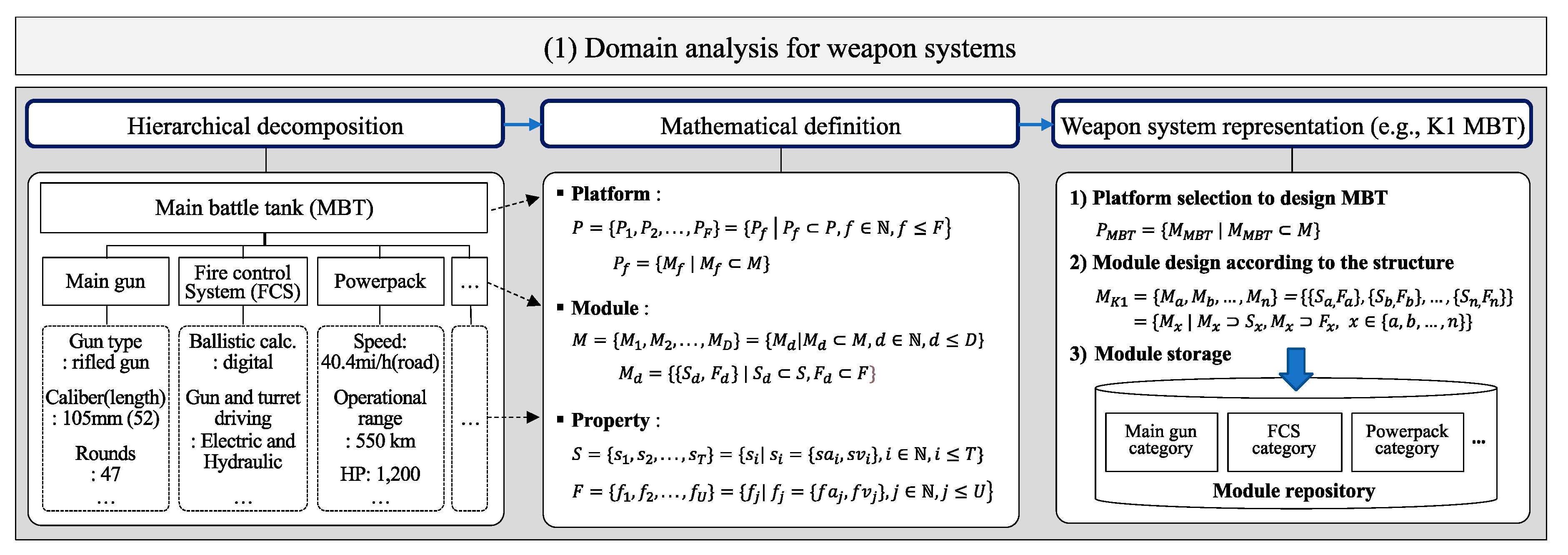
3.1. Domain Analysis for Weapon Systems
3.1.1. Hierarchical Decomposition
It is necessary to identify the structural and functional properties of the actual weapon system because formalizing the properties and constraints enables the simple automation of the reusing and modeling process. The present authors referred to a handbook of work breakdown structure (WBS) of the US Department of Defense (DoD) [
21], which provides a manual for the hierarchical structures of various weapon systems, in an attempt to establish the structural characteristics and procedural systemicity. Here, the WBS can be employed to analyze a whole system with its subsystems and relationships among the system constituents. In particular, the function of a weapon system can be elicited through this structure.
Figure 2 illustrates an example of the functional properties deduced from the hierarchical structure of a surface vehicle system based on WBS. The surface vehicle system roughly consists of six parts, such as “Special equipment”, “Turret assembly”, “Frame/Body”, “Vehicle assembly”, “Survivability system”, and “Armaments”. In addition, the assembly part can be divided into sub-components.
Based on the hierarchy, it is possible to derive the minimal units as design modules and the weapon system platforms for modeling. The platform is a set of components that are shared by weapon systems of the same category [
22,
23], and it is assumed to be a template for weapon system modeling. To design the template, the commonality and variability of weapon systems involved in the same category should be identified. At this time, the structure and components of the WBS can be regarded as the commonality of weapon systems involved in the same category, and the variants of weapons can be modeled by the replacement of the components. Using the nodes in
Figure 2, an example of the template can be expressed as a combination of the nodes shaded in gray, and the functional characteristics in dotted line nodes derived from them. Each component of the platform is designed, stored, and used in the form of a module.
3.1.2. Mathematical Definition
The weapon system can have multiple platforms depending on its form, and each platform can be represented by a combination of constituents. In this paper, the platform of the weapon system composed of constituents called modules is defined in the form of a set. Similarly, each module can be expressed through a combination of different structural and functional properties, each consisting of a pair of attributes and values.
All structural and functional properties can be defined in the form of a set ; . The subscripts and denote the number of elements in each set; and are structural and functional attributes and values, respectively. The binary relation () from () to () is a subset of . signifies the connection of the structural properties with the related functional properties and can be defined as Similarly, a module is formed by the configuration of the selected structural and functional properties. The module, which is represented in , is expressed as The entire set that contains the module is defined as . The subscript indicates the number of elements of the set . A platform to model a weapon system consists of a subset of the entire module set, and is defined as . In addition, the set of all platforms is expressed as , and they are classified according to their types. A weapon system comprises a subset of the entire platform set, and is defined as .
3.1.3. Weapon System Representation
To generalize the model design process, we re-express the characteristics of existing weapon systems using a previously designed structure, which is defined as a necessary platform and includes a set of modules satisfying the structural and functional characteristics. The sets of required design property, structural property, and functional property can be defined as , , and , respectively. The subscripts represent the number of elements in each set. The set of required design properties should be included in the union set of structural and functional properties, and can be represented as . The set of modules that meet the structural requirements can be defined as . Similarly, the set satisfying the functional requirements can be expressed as .
However, explaining the design of a model through the set of modules is limited in representing the contextual validity of the used constituents. In this context, an ontology structure can be utilized to overcome the constraints, and the example in
Figure 3 illustrates the generalized template in the form of an ontology for weapon system modeling using the hierarchical and horizontal relations among elements.
The process to select a proper template class and its instance is also applied equally to each module organizing the template instance. A structural module class can contain several functional classes, and the module instances are selected by retrieving the module that has properties corresponding to the requirements. Each module class contains property classes and instances constructing each module. Every property class includes the classes of attributes and values, and the combination of each instance represents a property instance. Moreover, this construction can be used in the process of retrieving and modifying weapon system models that satisfy the demands.
3.2. Entity Modeling with Case-Based Reasoning
Modeling a weapon system is possible through a combination of the designed modules. However, an increase in the number of modules composing a model increases the factors that the designers need to consider for modeling, and it also hinders the designers from guaranteeing consistent quality for the same object modeling [
4]. Therefore, the design of an intelligent modeling process that systematically considers the related factors is required. Prior to the process design, considering the feature whereby weapon systems in the same category share a common structure and are slightly different from each other, a modeling method that partially modifies an existing model according to the requirements is considered. From this perspective, the concept of CBR can be utilized, and
Figure 4 explains the overall process of systematic modeling using CBR. Since the important point is the actualization of the CBR process, which enables the generation of design specifications, the present authors attempted to design the sub-processes in detail to realize each process of CBR. The overall process consists of four steps: Analyzing requirements, retrieving similar cases from the case base, reusing or revising the cases, and retaining the cases [
17,
24].
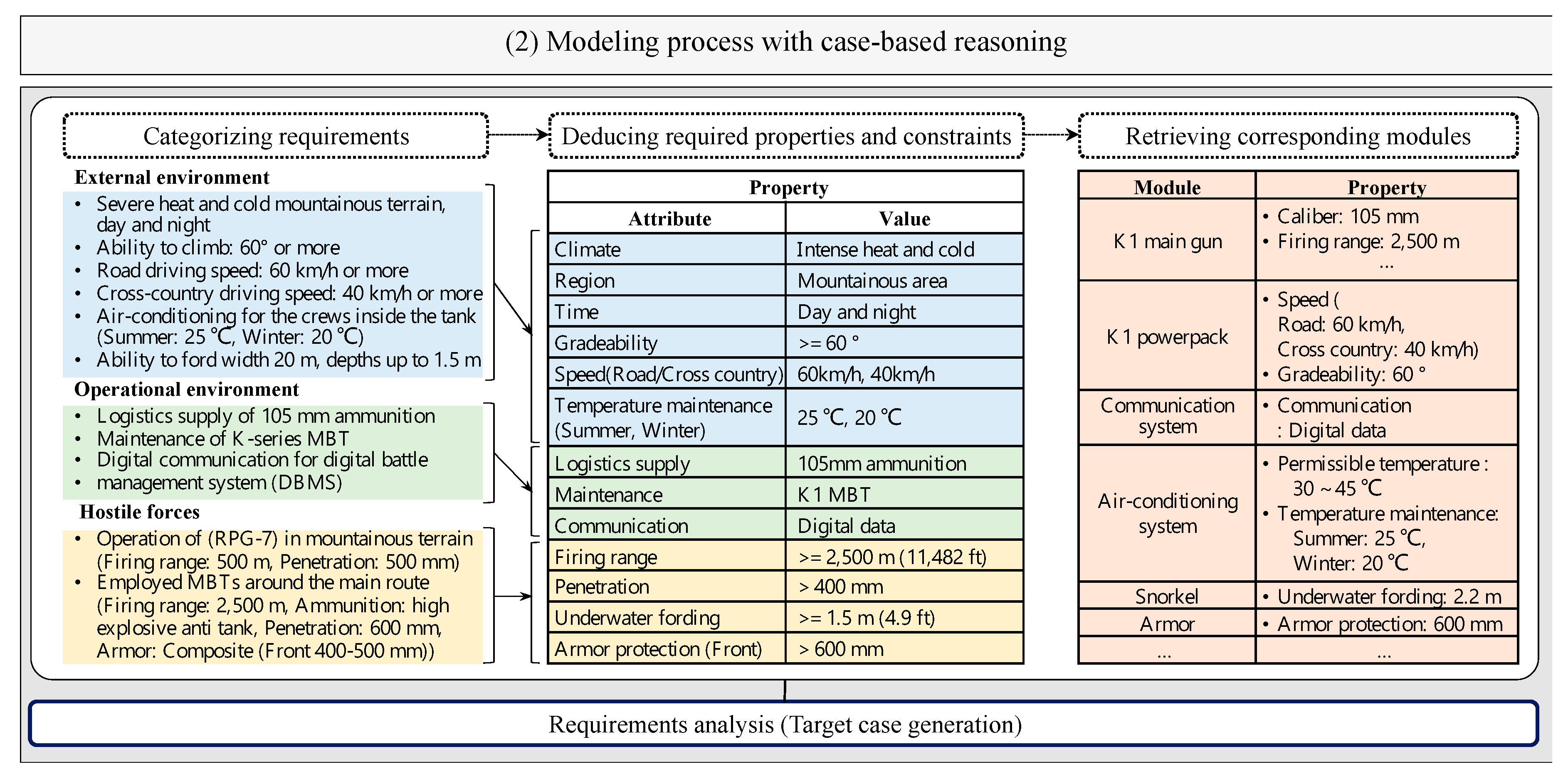
3.2.1. Requirement Analysis
The development of modern weapon systems requires a comprehensive understanding from the context of varying warfare perspectives. Based on this perspective, requirements can be assumed to be the characteristics of the equipment, enabling a designed model to interact with the surroundings. The features of the required model can change according to the perspective of the interaction between the model and the surroundings, and an analysis of the expected interaction is needed. The analysis can be utilized to deduce the structural and functional properties to respond to a given combat situation. A procedural example is as follows: When an attack is expected where an enemy using an anti-tank gun strikes a vehicle with projectiles, composite armors can be used to guard the vehicle against the projectiles. This procedure is explained in
Table A1 of the
Appendix A.
With this premise, the physical properties that are required to correspond to expected threats can be logically derived in terms of the interaction between attack and defense. In addition, it is necessary to consider not only the interaction but also the constraints resulting from the operational environment to elicit the weapon system properties. This means that the required physical properties can be affected by the environment of logistics, maintenance support, and communication systems. Hence, these factors are utilized to realize the physical properties fulfilled by the environmental limits. The requirements are represented in accordance with the structure of the case and are then used as input data for the retrieval of similar cases.
3.2.2. Case Design
The cases of CBR are generally categorized as previous (P) and target (T) cases. While the former consists of a problem and its solution description, the latter consists only of the description of a problem [
25]. In this study, the (P) case is organized with a certain operational environment and the weapon system model, enabling it to respond to the scenario, and the (T) case represents the specifications for the expected operational environment and the required functions of the weapon system. Based on the case structures, similar cases of the weapon system are utilized to design the new model specification that fulfills the requirements. For cases that need to be represented in a formal structure to ensure the ease of retrieving and reusing the cases [
4], the present authors designed the case structure as below.
Specifically, the (P) case is designed with management information, a modeling platform, and external and operational environments of a weapon system. Similarly, the (T) case consists of a modeling platform, expected external and operational environment of the required weapon system, and its specifications for the modules. The generalized structure of the (P) and (T) cases can be found in
Table A2 of the
Appendix A. The (T) case is used as the input data to retrieve the corresponding (P) case. In addition, for the systematic management and search of cases, the designed cases are classified and stored in the case base.
3.2.3. Case Retrieval
The retrieval of cases refers to the process of searching for cases that are similar to the target case from the case base [
4]. In this section, the process is designed for the retrieval of cases that are suitable for the expected environment from the case-memory structure. The constituents involved in the cases are the explicit properties that determine the similarity between the previous cases and the target case. Based on a direct comparison of the cases, the model specifications that are usable in similar operational circumstances can be derived. The following sub-sections focus on explaining the sub-processes of the retrieval process.
Environment Similarity
The (P) and (T) cases contain the specifications of the environmental conditions in which the weapon system operates and the functional characteristics of the participating entities in combat situations are known. By comparing the specifications of both cases, the similarity between them can be quantified. The Jaccard similarity can be used to calculate the similarity between two sets by using the number of set elements, and it is defined as
[
26,
27]. This feature makes it possible to utilize cases that are designed using the set theory. For example, it is assumed that
. Then, the Jaccard similarity is
0.333. However, this method expresses the ratio of the intersection to the union of the two sets, and the similarity can be decreased when the number of elements in the previous case increases. Hence, in this study, the Jaccard similarity was modified as the ratio of the intersection to the target case instead of the union set of the previous and target cases, and it is defined as
. The similarity of environmental conditions is calculated by the weighted sum of each similarity of the expected environment (
) and the functional demands (
) of the participants. Each weighted value has a value between 0 and 1, and the sum of the values is 1. Equation (1) indicates the similarity of the environmental condition (EC), and is based on Equation (2).
Configuration Similarity
The designed model in the combination with the modules based on the template can represent multiple variants of the model using certain modules according to the structural and functional characteristics. The case similarity for the organization of the modules can be quantified by comparing the configuration modules and their properties. The properties can be categorized into qualitative and quantitative types. The qualitative (QL) similarity is calculated using the Jaccard similarity that was modified in this study, and the quantitative (QN) similarity is determined by averaging the ratio of the Euclidean distance to a large value for each QN property. Consequently, the similarity of the module configurations is calculated by the weighted sum of these similarity values. Equation (3), which is based on Equations (4) and (5), determines the similarity of configuring modules and their properties. Equation (4) provides the similarity score for the sets of QL values of the modules that are involved in the previous case and the target case using the modified Jaccard similarity. In the same way, Equation (5) offers the similarity score for the sets of QN values of the previous and target modules using the average of the ratio of the Euclidean distance for the corresponding QN values.
To determine the similarity between the previous and target cases, each similarity score of the environmental conditions, as well as the configuring modules is considered simultaneously. Thus, the previous cases that are employed to provide the module configurations in which the required functions are supported in a certain surrounding can be selected using the similarity score. Equation (6) offers the similarity score for the previous and target cases.
Retrieval Process Using Similarity
The procedure to retrieve the cases similar to the target case from the previous cases using the similarity score is shown in
Table 1.
It retrieves the cases by sharing the platform with the target case from the case base and calculates the similarity scores. The top three cases of the scores are provided as the case similar to the target case. One of the results can be reused as a solution or can be modified according to the requirements.
3.2.4. Case Reuse and Revision
When a similar case itself can be used as the solution of the expected situation, the cases are reused. However, although the case has a high similarity score, not all factors of the case can correspond with the given situation. At this time, the selected case requires a modifying process. The process of modifying the selected case to respond to the expected situation is shown in
Table 2.
The procedure consists of three parts: Part 1 adds new modules to the existing model in which modules are configured, part 2 removes the existing module from the module-based model, and part 3 replaces an element of the model with a new element. The replacement process sequentially executes part 1 and part 2 of the algorithm.
3.3. Simulation Modeling
3.3.1. Interaction Modeling for Simulation
The given environment and the interaction of attack and defense between the participating entities can be utilized not only to analyze requirements for modeling but also to simulate the design to confirm the validation. The simulation model for the interaction is designed to produce various results for the success of attack and defense under the same conditions from the perspective of probability.
Figure 5 illustrates the simulation process of the interaction model.
4. Case Study: Project for Enhancing K1 Tank
This study attempts to compare a weapon system model that is designed using the proposed method with a real weapon system. We selected a main battle tank (MBT) as the modeling object, designed the configuring modules and cases based on the different types of MBT employed in South Korea, and tried to generate an appropriate model that can respond to the environmental requirements using the CBR process. The designed model was then compared with an existing MBT that has a similar function, to validate its practicality.
4.1. Main Battle Tank (MBT) Modeling
Common platforms and the constituents of existing MBTs are derived through hierarchical decomposition prior to use in the modeling process using CBR.
Figure 6 illustrates the actions for the domain analysis.
The decomposition is shown in the first part of the illustration, and the examples of the results for all K-series MBTs are provided in
Table A3 of the
Appendix A.
The derived platforms, modules, and properties are modeled in mathematical structures, and can be found in the second part of the figure below. In order to re-express the existing weapon systems using the designed platforms and modules, an appropriate platform is selected and the weapons are then decomposed according to the platform structure. The weapon characteristics are reflected in the modules configuring the platform through the module design. The designed modules are classified as repositories. To design an actual weapon system, all design constraints among the actual parts need to be satisfied, but in this study, the modules that have the same series are designed assuming that they are compatible with each other.
The requirements for the tank to be designed to overcome the expected environmental constraints are assumed as the first part of
Figure 7.
The attribute-values to satisfy the requirements are given in the second part of the illustrations below. The modules, including properties corresponding to the requirements, are retrieved from the module repository, and they are added to the module list that is used to retrieve similar cases by comparing the platform, environmental conditions, and module configuration. Furthermore, the constraints for the environment and attribute-values are used as criteria for the addition, deletion, and replacement of the modules in the revision process.
The previous case comprises environmental conditions, required functions, and a set of modules to support the conditions and functions. Each case is classified in the case base and is then used in the case retrieval process. As an example of a previous case, the construction of the K1 MBT case is depicted in the first part of
Figure 8.
The target case that is provided from the requirement analysis is used to retrieve similar previous cases from the case base. Previous cases with high values based on similarity scores were chosen. The similarity score is calculated based on the formulas in
Section 3.2.3, and the results of the similarity evaluation between K-series MBTs and the target case can be found in the second part of the figure. The details of K-series MBTs re-expressed in the proposed form are shown in
Table A3. In the retrieval process, cases having high similarity scores but failing to meet operational environmental constraints, such as maintenance support, are excluded. This is because such cases cannot fulfill the requirements solely through the modification of the chosen case. Furthermore, the most similar case cannot satisfy every requirement although it may have the highest similarity score. Thus, a revision process is required for the selected case. This is shown in the sixth part of the illustration below. Here, based on the revision process introduced in
Section 3.2.3, the revised K1 case according to the given specifications is depicted in the last part of the figure. That is, by using the revision process, it is possible to design the weapon system model that fulfils the requirements.
With regard to the three expected benefits mentioned in the introduction of the paper, this section confirmed the first and second benefits. First, the design methods of the generalized structures and modules for modeling are provided. Second, the intelligent modeling method that uses CBR provides a procedure for automatic modeling that satisfies the requirements.
4.2. Model Evaluation
The results of the modeling based on the CBR process are validated according to their validity and practicality. With respect to the validity, the designed model needs to confirm whether it is able to appropriately respond to the surrounding environment, and whether the model can react to the acting participants in the combat situation. With respect to the practicality, the modeling result is compared with the existing weapon system to affirm whether the model is practical.
4.2.1. Model Validity
The model validity for the given environmental conditions requires the checking of whether the model can meet certain criteria under given conditions. For the example of an MBT, the conditions for the external environment include seasonal intense heat and cold and mountainous areas. The criteria are the temperature of the compartment, gradeability, and roadability. In addition, the conditions of the operational environment are logistics, maintenance, and communication systems, and their criteria are the supplied ammunitions, ability to perform maintenance, as well as communication methods. This can be used to verify that the generated model satisfies the environmental conditions and criteria. The revised case in the third part of
Figure 8 shows that the design requirements are fulfilled through the replacement and addition of modules for the selected case.
4.2.2. Model Practicality
To confirm the practicality of the modeling result, the present authors tried to compare the designed model with the real tank case having similar structures and functions. For comparison, the K1E1 tank was selected as the real reference model. This MBT is an improved version of the old K1 tank, which corresponds to the requirements of future warfare, enabling the combined operation with a new K2 tank. From this perspective, the aspect of improved model design based on the existing design is consistent with the purpose of this study. Thus, the K1E1 case was used as the reference model. The K1E1 tank is re-expressed with the configuration of modules, and then it is compared with the configuring modules of the revised case. The construction of the K1E1 tank is shown in
Figure 9, where the rectangle in the bold line is the module shared in both K1E1 and the revised case, and the rectangle in the dotted line is the additional module mounted on the K1E1 tank. The designed model in
Section 4.1 shares many of the common features with the K1E1 tank illustrated in
Figure 9 (14/18 = 0.78 based on K1E1), and the designed model is realistic because the development of the K1E1 tank is completed, and the implementation of the performance improvement project has been planned from 2021 to 2038 according to a press release [
28].
4.2.3. Model Reusability
When the K1E1 case in
Figure 9 is assumed to be retained to the case base as a new case, it can be utilized in the modeling process of another tank model. For example, under the assumption that the armor protection and firing range of the enemy are improved, the operational environment conditions are fulfilled, and the retained case can be reused by the module replacement for the main gun and armor in the design process of a new tank. Specifically, a 120-mm smoothbore gun module is remounted instead of a 105-mm rifled gun module. The tank model designed in this way is realistic because it is almost similar to the existing K1A2 tank in terms of its configuration and expected performance (17/18 = 0.94).
4.3. Model Simulation
This work devises a simulation model to test the response capability of the designed weapon system against expected enemy threats. This simulation is utilized to confirm whether the designed model can survive in a given situation through repetitive interactions between combatant entities in terms of attack and defense. The modeling process of the interactions is presented in the first part of
Figure 10. The generation of procedural codes for each function based on functional and structural modules, and a simulation procedure modeling using the codes can be observed in the second part of the illustration below. Each procedural code that constitutes this model is executed using a simulation engine, which enables the results of the interactions between the model and the objects to be identified. This confirms that it is possible to provide a testable simulation using the method proposed in this paper, which is among the expected benefits mentioned in the introduction.
5. Experimental Results
The case study showed that the method we proposed is applicable to modeling and simulating weapon systems. However, it is necessary to verify that the results reflect the benefits of the method designed in this study. This section identifies whether the method proposed in this study can satisfy the expected advantages, and the modeling and simulation results in relation to the expected advantages of the proposed method are outlined in detail.
The first expected advantage is the provision of generalized structures and modules for weapon system modeling.
Figure 6 shows the design of the platform and configuration modules for modeling the weapon system through the elicitation of the structure and the composition and mathematical definition through a hierarchical analysis of the actual weapon system. Through the proposed method, the characteristics of each MBT of K-series MBTs can be expressed through the common structure and changeable configuration modules, and the results can be identified in
Table A3 in the
Appendix A. This demonstrates that the devised method satisfies the first aspect.
The second aspect is concerning whether the method could generate modeling that reflects the design requirements by using an intelligent method. The requirement analysis that can be observed in
Figure 7 supports the formalization of the expected environmental conditions and hostile forces situation into required properties and constraints to retrieve platforms and modules for an MBT. The deduced properties, constraints, and modules are used as inputs for the modeling process using CBR, which is one of the artificial intelligence paradigms.
Figure 8 shows that the required MBT model that satisfies all the required conditions can be designed through the CBR process intelligently. It means that the second aspect can be satisfied through the proposed method.
The third aspect is regarding whether the proposed method can provide simulations to test the designed models in the expected circumstances. The environment where the designed MBT model will be deployed assumes an engagement situation with enemy guerillas and MBTs operating anti-tank weapons. To this end, the simulation experiment assumes multiple combat situations by varying the number and combination of combatant entities to interact with the designed MBT model, and it is based on the interaction process described in
Section 3.3.1. To confirm the suitability of the generated MBT model, the survivability of a similar model that is not modified is compared with that of the revised model. The result of the comparison of the designed model and K1 tank in the expected situation of
Figure 10 is shown below.
Figure 11a illustrates the survivability between the newly designed tank and existing K1 tank according to the only increase in the number of counterforce tanks. Similarly,
Figure 11b depicts their survivability ratio considering only the number of anti-tank guns. These results demonstrate that the designed model is more responsive to the specified enemy threats than the K1 tank with respect to the survivability rate.
In the same context, the survival rates of both the new and K1 tanks are compared in a situation where both guerrillas operating anti-tank guns and enemy MBTs that are deployed in the main route are considered with increasing numbers in
Figure 12.
Comprehensively, these results indicate that the new tank model can respond to the given situations and has a higher survivability rate than the model of the existing tank. The experimental data are presented in
Table A4 of the
Appendix A. This means that the proposed method can provide simulations to identify the reaction capability of the design model in the expected circumstance.
6. Conclusions
This study proposes a method to support the automated design of weapon system models for simulation. To design the method, it is necessary to consider how to reduce resource consumption and solve modeling complexity. Thus, the goal of this paper is not only to propose a modeling method and its logical automation, but also to perform simulation modeling to test the designed model.
The proposed method designs the hierarchical structure of weapon systems in a mathematical structure, applies it to the design of modules and modeling using the CBR process, and validates the generated model using simulations. That is, it can offer a total solution to cover the design of automated modeling and simulation. However, related studies do not cover the entire process, including the design of the reusable modeling method, its systematic procedure, and simulation for evaluation, but treat the process partially. Using this approach, it is possible to provide designers with a rapid design of weapon system models and to verify their suitability for operation in expected environments.
Consequently, the result of the case study based on the background of the K1 tank upgrade project demonstrates the validity and practicality of the proposed modeling method. Moreover, the simulation shows that the designed model has a higher survivability rate than the reference model. This means that the proposed method can be utilized to design and upgrade weapon systems according to the changing requirements.
The main contribution of this paper is to present IM4MnS, which enables the modeling process of weapon systems and the simulation of the designed models. The proposed method has the following three advantages. First, the method can offer generalized structures and modules for weapon system modeling. Second, the method can generate models that reflect design requirements using an intelligent method. Third, the method can provide a simulation to test the designed model in the expected environment. In addition, the process of IM4MnS can be utilized in the design and evaluation of not only weapon systems but also customized products.
The example in the case study assumes that the weapon systems in the same category can share the configuring modules. Nonetheless, these weapon systems, even the same parts, may differ in their actual structure, and may be limited in terms of the ease with which they can be mounted on other weapon systems. Thus, in future studies, the authors will investigate these modeling constraints, and will focus on the CBR-based modeling process and develop an application that provides an automated modeling process and its simulation. Furthermore, we will extend this study to determine its application to the design and verification of customized products.
Author Contributions
Conceptualization, D.K. and Y.S.; formal analysis, D.K. and D.J.; funding acquisition, Y.S.; investigation, D.K. and D.J.; methodology, D.K.; project administration, Y.S.; software, D.K.; supervision, Y.S.; validation, D.K., D.J., and Y.S.; visualization, D.K.; writing—original draft, D.K.; writing—review and editing, D.K. All authors have read and agreed to the published version of the manuscript.
Funding
This research was funded by the Defense Acquisition Program Administration and the Agency for Defense Development, grant numbers UD140022PD and UD110006MD.
Acknowledgments
We would like to thank the reviewers and editors for reviewing this article.
Conflicts of Interest
The authors declare no conflict of interest.
Appendix A
Table A1.
Process to analyze contextual requirements.
Table A1.
Process to analyze contextual requirements.
| Notations | the index assigned to enemies
the number of enemies
the index assigned to the element of and respectively
the number of the elements of and respectively
the sets of the functions, module properties, and
environmental conditions of the enemy with the index
: the platform for enemy consisting of module instances which contain
the set of derived functions to respond to
the -th module in the entire module set
the set of the modules to respond to the related and |
| Step 1: | For integer 1 to do
Find out all of functions, environmental conditions and equipment specifications of enemies |
| Step 1.1: | Append the results to each list of the factors
(the equipment specifications of each enemy)
(the environmental conditions of each enemy) |
| Step 1.2: | Derive expected from and |
| Step 2: | For integer 1 to do
Derive functions to respond to each element of and append them to the list
(functions responding to each element of ) |
| Step 3: | For integer 1 to do |
| | Find out containing each element of from the entire module set |
| Step 3.1: | Confirm whether each module instance can respond to the related and |
| | If the instance can respond to the related and
append (the module instance)
Else
Move to the next module instance |
Table A2.
Generalized structure for previous and target case.
Table A2.
Generalized structure for previous and target case.
| Case Type | Element | Sub-Element |
|---|
Previous case
element | Case data | id | date | name |
Common
elements | Platform | type |
Environment
| (climate, region, time): (,)...(,) |
(logistic supply, maintenance, communication):
(,)...(,) |
Functions
| (behavior, object, measure):
()... () |
Previous case
elements | Module
property
| Structural property | (attribute, value): ()...()
= ... |
| Functional property | (attribute, value): ()...()
= ... |
Target case
element | Required
property
| Structural property | (attribute, value): ()...()
= ... |
| Functional property | (attribute, value): ()...()
= ... |
Table A3.
Specifications of K-series main battle tanks (MBT).
Table A3.
Specifications of K-series main battle tanks (MBT).
| Component | Sub-Component | Attribute | K1 | K1A1 | K2 |
|---|
| Turret assembly | Main gun | Type | Rifled gun | Smoothbore |
| Caliber (length) | 105 mm (52) | 120 mm (44) | 120 mm (55) |
| Rounds | 47 | 32 | 40 |
| Ammo Loading | Manual loader | Auto loader |
| Firing range | 2500 m (8202 ft) | 3500 m (11,482 ft) | 3000 m (9842.5 ft) |
Ammunition
Type | APAM, HESH, APFSDS, HEAT-MP, HEAT-FS | APFSDS-T, HEAT-MP |
Fire control system
(FCS) | Gun and turret driving | Electric and Hydraulic | Electric |
| Gun stabilization | 2xis stabilization |
| Ballistic computing | Digital |
| Gunner’s primary sight | Day and night, Optics and thermal, 2xis stabilization, Laser range finder |
| Commander’s panoramic sight | 360-degree view, Day, Optics, 2xis stabilization, Laser range finder | 360-degree view, Day and night, Optics and thermal, 2xis stabilization, Laser range finder |
Frame
/Body | Compart-ment | Crews | 4 (Commander, Gunner, Loader, Driver) | 3 (except Loader) |
| Size | L: 9.67 m (31.7 ft) * W: 3.59 m (11.8 ft) * H: 2.25 m (7.4 ft) | L: 9.71 m (31.8 ft) * W: 3.59 m (11.8 ft) * H: 2.25 m (7.4 ft) | L: 10.8 m (35.4 ft) * W: 3.6 m (11.8 ft) *
H: 2.4 m (7.9 ft) |
| Vehicle assembly | Powerpack | Speed | Road: 65 km/h
(40.4 mi/h),
Cross country:
40 km/h (24.9 mi) | Road: 60 km/h
(37.3 mi/h)
Cross country:
40k m/h (24.9 mi) | Road: 70 km/h
(43.5 mi/h)
Cross country:
50 km/h (31.1 mi) |
| Operational range | 550 km (341.8 mi) | 500 km (310.7 mi) | 450 km (279.6 mi) |
| HP | 1200 | 1500 |
| HP/ton | 23.5 | 22.0 | 27.3 |
| Gradeability | 60° (max) |
| Gear shifting | 4-speed forward,
2-speed reverse | 6-speed forward,
3-speed reverse |
| Suspension | Type | Steel torsion bars - Hydropneumatic suspension system | Semi-active, in-arm suspension unit |
| Attitude control | Pitch | Pitch, Roll, Height |
| Special equipment | Electronic systems | Communication | Radio system | C4I network |
| Combat identification | Not supported | Interrogation signals & responses
(Identificiation friend or foe (IFF)) |
| Navigation | Not supported | GPS & INS |
| Temperture maintenance | Not supported | Summer: 25 °C,
Winter: 20 °C |
| Battlefield management | Not supported | Digital battlefield management system |
| Snorkel | Underwater fording | 2.2 m (7.2 ft) | 4.1 m (13.5 ft) |
| Survivability system | Active protection system | Type | - | Soft kill |
| Equipment | - | Smoke grenade launcher
(6 rounds * 2) |
NBC protection
system | Type | Individual | Collective |
| Equipment | Individual protective equipment | NBC positive pressure, Neutron screen liner |
| Armaments | Secondary weapons | Type | Machine guns |
| Equipment | 12.7 mm K6, 7.62 mm M60D, 7.62 mm M60E2-1 |
| Armor | Type | Composite armor | Composite armor, ERA |
| Front protection | 400–500 mm | 600–700 mm | 800–850 mm |
Table A4.
Tables showing the survivability of K1 and the new tanks with increasing number of enemy anti-tank guns and MBTs (a) Survivability of K1 tank model (b) Survivability of the new tank model.
Table A4.
Tables showing the survivability of K1 and the new tanks with increasing number of enemy anti-tank guns and MBTs (a) Survivability of K1 tank model (b) Survivability of the new tank model.
| (a) | (Trimmed Mean) |
Survivability
(New Tank) | The number of MBT |
| 0 | 1 | 2 | 3 | 4 | 5 | 6 | 7 |
The number
of
RPG-7 | 0 | 0.00 | 0.734 | 0.593 | 0.495 | 0.428 | 0.372 | 0.343 | 0.306 |
| 1 | 1.00 | 0.706 | 0.569 | 0.460 | 0.406 | 0.342 | 0.298 | 0.285 |
| 2 | 0.994 | 0.709 | 0.521 | 0.434 | 0.359 | 0.326 | 0.280 | 0.243 |
| 3 | 0.983 | 0.724 | 0.545 | 0.426 | 0.351 | 0.299 | 0.262 | 0.242 |
| 4 | 0.973 | 0.697 | 0.512 | 0.419 | 0.323 | 0.276 | 0.251 | 0.225 |
| 5 | 0.954 | 0.699 | 0.503 | 0.389 | 0.334 | 0.273 | 0.240 | 0.206 |
| 6 | 0.934 | 0.707 | 0.509 | 0.388 | 0.315 | 0.269 | 0.225 | 0.203 |
| 7 | 0.914 | 0.690 | 0.505 | 0.381 | 0.307 | 0.245 | 0.223 | 0.185 |
| (b) | (Trimmed Mean) |
Survivability
(K1 Tank) | The number of MBT |
| 0 | 1 | 2 | 3 | 4 | 5 | 6 | 7 |
The number
of
RPG-7 | 0 | 0.00 | 0.476 | 0.328 | 0.253 | 0.183 | 0.151 | 0.135 | 0.122 |
| 1 | 1.00 | 0.456 | 0.273 | 0.200 | 0.171 | 0.141 | 0.119 | 0.105 |
| 2 | 0.989 | 0.457 | 0.271 | 0.201 | 0.148 | 0.117 | 0.105 | 0.093 |
| 3 | 0.964 | 0.448 | 0.260 | 0.172 | 0.131 | 0.107 | 0.092 | 0.087 |
| 4 | 0.932 | 0.458 | 0.249 | 0.163 | 0.112 | 0.098 | 0.089 | 0.077 |
| 5 | 0.916 | 0.457 | 0.235 | 0.149 | 0.108 | 0.086 | 0.079 | 0.066 |
| 6 | 0.865 | 0.447 | 0.240 | 0.147 | 0.107 | 0.080 | 0.075 | 0.066 |
| 7 | 0.817 | 0.439 | 0.238 | 0.143 | 0.102 | 0.076 | 0.068 | 0.065 |
References
- Cil, I.; Mala, M. A multi-agent architecture for modelling and simulation of small military unit combat in asymmetric warfare. Expert Syst. Appl. 2010, 37, 1331–1343. [Google Scholar] [CrossRef]
- Hill, R.R.; Miller, J.O.; McIntyre, G.A. Applications of discrete event simulation modeling to military problems. In Proceedings of the 2001 Winter Simulation Conference, Arlington, VA, USA, 9–12 December 2001; pp. 780–788. [Google Scholar]
- Rahman, A.H.; Malik, A.S.; Kumar, J.R.; Balaguru, V.; Sivakumar, P. Design Configuration of a Generation Next Main Battle Tank for Future Combat. Def. Sci. J. 2017, 67, 343–353. [Google Scholar] [CrossRef]
- Kim, D.; Seo, Y.; Sheen, D.-M. Dynamic component reconfiguration system using case-based reasoning for weapons system in DM&S: Guided weapon case. In Proceedings of the 2015 European Modelling Symposium, Madrid, Spain, 6–8 October 2015; pp. 9–13. [Google Scholar]
- Grznár, P.; Gregor, M.; Krajčovič, M.; Mozol, Š.; Schickerle, M.; Vavrík, V.; Ďurica, L.; Marschall, M.; Bielik, T. Modeling and Simulation of Processes in a Factory of the Future. Appl. Sci. 2020, 10, 4503. [Google Scholar] [CrossRef]
- Smith, R.D. Essential techniques for military modeling and simulation. In Proceedings of the 1998 Winter Simulation Conference, Washington, DC, USA, 13–16 December 1998; pp. 805–812. [Google Scholar]
- Page, E.H.; Smith, R. Introduction to military training simulation: A guide for discrete event simulationists. In Proceedings of the 1998 Winter Simulation Conference, Washington, DC, USA, 13–16 December 1998; pp. 53–60. [Google Scholar]
- Park, S.C.; Kwon, Y.; Seong, K.; Pyun, J. Simulation framework for small scale engagement. Comput. Ind. Eng. 2010, 59, 463–472. [Google Scholar] [CrossRef]
- Bowers, J.; Elsawah, S.; Ryan, M. Reusable modules to support rapid model building: A case study of defence force design. In Proceedings of the 2017 INCOSE International Symposium, Adelaide, Australia, 15–20 July 2017; pp. 1539–1553. [Google Scholar]
- Levandowski, C.; Jiao, J.R.; Johannesson, H. A two-stage model of adaptable product platform for engineering-to-order configuration design. J. Eng. Des. 2015, 26, 1–16. [Google Scholar] [CrossRef]
- Gui, J.-K.; Mäntylä, M. Functional understanding of assembly modelling. Comput. Des. 1994, 26, 435–451. [Google Scholar] [CrossRef]
- Zeng, Y.; Gu, P. A science-based approach to product design theory Part I: Formulation and formalization of design process. Robot. Comput. Manuf. 1999, 15, 331–339. [Google Scholar] [CrossRef]
- Suh, S.-H.; Seo, Y.; Lee, S.-M.; Choi, T.-H.; Jeong, G.-S.; Kim, D.-Y. Modelling and Implementation of Internet-Based Virtual Machine Tools. Int. J. Adv. Manuf. Technol. 2003, 21, 516–522. [Google Scholar] [CrossRef]
- Seo, Y.; Hong, D.-P.; Kim, I.; Kim, T.; Sheen, D.; Lee, G.-B. Structure modeling of machine tools and Internet-based implementation. In Proceedings of the 2005 Winter Simulation Conference, Orlando, FL, USA, 4–7 December 2005; pp. 1699–1704. [Google Scholar]
- Lee, J.-O.; Lee, J.-J.; Suk, J.-B.; Seo, Y.-H. A development of the dynamic reconfigurable components based on software product line: Guided weapon system. J. Korea Soc. Simul. 2010, 19, 179–188. [Google Scholar]
- Luo, Z.; Shang, J.; Wei, G.; Ren, L. Module-based structure design of wheeled mobile robot. Mech. Sci. 2018, 9, 103–121. [Google Scholar] [CrossRef]
- Asim, Y.; Raza, B.; Asim, Y.; Shahaid, A.R.; Alquhayz, H. An Adaptive Model for Identification of Influential Bloggers Based on Case-Based Reasoning Using Random Forest. IEEE Access 2019, 7, 87732–87749. [Google Scholar] [CrossRef]
- Zhu, Z.; Hsu, H.-Y.; Nagalingam, S.; Geng, L. Literature review on the creativity of CBR applications. Artif. Intell. Rev. 2011, 40, 379–390. [Google Scholar] [CrossRef]
- Tseng, H.-E.; Chang, C.-C.; Chang, S.-H. Applying case-based reasoning for product configuration in mass customization environments. Expert Syst. Appl. 2005, 29, 913–925. [Google Scholar] [CrossRef]
- Nie, Y.; Yin, G.F.; Zhao, X.F.; Fang, H.; Yin, Y. Rapid Locking Assembly Variant Design Based on Product Configuration Model and CBR. Appl. Mech. Mater. 2011, 48, 868–872. [Google Scholar] [CrossRef]
- DoD. Work Breakdown Structures for Defense Materiel Items; DoD: Washington, DC, USA, 2011. [Google Scholar]
- Jiao, J.R.; Simpson, T.W.; Siddique, Z. Product family design and platform-based product development: A state-of-the-art review. J. Intell. Manuf. 2007, 18, 5–29. [Google Scholar] [CrossRef]
- Moon, S.K.; Shu, J.; Simpson, T.W.; Kumara, S.R. A module-based service model for mass customization: Service family design. IIE Trans. 2010, 43, 153–163. [Google Scholar] [CrossRef]
- Lu, J.; Bai, D.; Zhang, N.; Yu, T.; Zhang, X. Fuzzy Case-Based Reasoning System. Appl. Sci. 2016, 6, 189. [Google Scholar] [CrossRef]
- Qin, Y.; Lu, W.; Qi, Q.; Liu, X.; Huang, M.; Scott, P.J.; Jiang, X.J. Towards an ontology-supported case-based reasoning approach for computer-aided tolerance specification. Knowl. Based Syst. 2018, 141, 129–147. [Google Scholar] [CrossRef]
- Zhang, D.; You, X.; Liu, S.; Yang, K. Multi-Colony Ant Colony Optimization Based on Generalized Jaccard Similarity Recommendation Strategy. IEEE Access 2019, 7, 157303–157317. [Google Scholar] [CrossRef]
- Yan, H.; Tang, Y. Collaborative Filtering Based on Gaussian Mixture Model and Improved Jaccard Similarity. IEEE Access 2019, 7, 118690–118701. [Google Scholar] [CrossRef]
- Results of the 123th Defense Acquisition Committee Work (DAPA Press Release). Available online: http://www.dapa.go.kr/dapa/na/ntt/selectNttInfo.do?bbsId=326&nttSn=32309&menuId=678 (accessed on 28 September 2020).
| Publisher’s Note: MDPI stays neutral with regard to jurisdictional claims in published maps and institutional affiliations. |
© 2020 by the authors. Licensee MDPI, Basel, Switzerland. This article is an open access article distributed under the terms and conditions of the Creative Commons Attribution (CC BY) license (http://creativecommons.org/licenses/by/4.0/).


