Abstract
The AC/DC hybrid microgrid has a large-scale and complex control process. It is of great significance and value to design a reasonable power coordination control strategy to maintain the power balance of the system. Based on hierarchical control, this paper designs a reasonable power coordination control strategy for AC/DC hybrid microgrid. For lower control, this paper designs a variety of control modes for each converter in different application scenarios. For the higher control, this paper analyzes the working mode of the system and designs the power coordination control strategy under the grid-connected and isolated island mode. In grid-connected operation, the DC bus voltage can be stabilized by adjusting the operation mode of the DC energy storage and the on-off of the secondary load. In isolated island operation, the DC sub-microgrid is the main microgrid, and the DC energy storage is the main power regulating equipment. This is based on the principle of “energy is in short supply in the system, DC energy storage finally discharge, energy supply exceeds demand in the system, DC energy storage gives priority to charging” of DC energy storage. By adjusting the control strategy of the micro-source, the reference power, and the on-off of the secondary load, the overall power balance is maintained. The Matlab/Simulink simulation software was used to build the AC/DC hybrid microgrid simulation model, which verified the effectiveness and stability of the proposed power coordination control strategy under various operating conditions.
1. Introduction
With the continuous update and development of science and technology, especially the continuous improvement of power electronic interface technology and modern automatic control theory, a small power generation, distribution, and electricity system “microgrid” has been formed, which integrates distributed generation (DG), energy management system, and load [1]. Whether it is AC microgrid or DC microgrid, when AC load and DC load coexist, a large number of converters are needed in the microgrid for electrical energy conversion, which will cause a certain amount of energy waste and increase economic costs [2]. The typical AC/DC hybrid microgrid is composed of AC subsystem, DC subsystem, and interlinking converter (ILC) [3]. The AC load and DC load can be connected to AC bus and DC bus, respectively, which can greatly reduce the number of power electronic converters and reduce unnecessary power loss. It is considered to be the mainstream structure of microgrid in the future.
The AC/DC hybrid microgrid can solve the problem of power conversion of the load because it contains one or more interlinking converters, various forms of DG, and energy storage units. How to reasonably control each power electronic converters to ensure the stability of the microgrid system has always been the research focus of experts and scholars.
Power control is the most important control mode in AC/DC hybrid microgrid. It is necessary to consider not only the control strategy of AC sub-microgrid and DC sub-microgrid but also the overall control strategy, that is, to ensure that power can flow in both directions between AC and DC sub-microgrid [4]. The power control for the DC microgrid is as follows: In Reference [5], Karlsson P et al. first used the droop control with different droop coefficients to rationally distribute the power of the system load. In Reference [6], Dragičević T. et al. proposed a hierarchical control strategy. The lower controller is used to divide the current equally, and the higher controller is used to recover the voltage, which can effectively solve the problem of bus voltage deviation. Anand S and others used global communication to obtain the output current of DG, and adopt an average current sharing control strategy to recover the bus voltage [7]. The power control of the AC microgrid is as follows: In Reference [8], Prodanovic M. et al. proposed a centralized control method, which consists of a centralized controller and a local controller. Among them, the centralized controller is responsible for calculating the reference value of the output current loop of each converter and then using the high-speed communication line to send to each converter, and finally being controlled by the local controller. In Reference [9], Mazumder SK et al. proposed to use of master–slave control technology, which includes a master converter and several slave converters. Each slave converter needs to track the output current of the master converter. The power control of AC/DC hybrid microgrid is as follows: In Reference [10], Simpson-Porco J W et al. adopted master–slave control technology to realize smooth and reliable energy exchange on both sides of the AC/DC hybrid microgrid. In Reference [11], Wang, H.Y. et al. proposed a hierarchical control strategy based on drooping control. Due to the different impedance between low-voltage and traditional high-voltage microgrids connected to transmission lines, the power coupling problem was caused. In Reference [12], Pequito S. et al. proposed a decentralized controller method for a large system, which is mainly divided into two layers. The first layer, through pretreatment, gives the relevant state matrix of the closed-loop system two ideal structural characteristics: there is no structural fixed mode. In the second layer, the control scheme can be chosen arbitrarily according to the needs, so that the method has diversity. In Reference [13], I. Kondratiev et al. proposed an improved layered control strategy to increase coordination ability in the original cooperative control theory characteristics and solved a series of problems that could not be solved by traditional linear methods. In Reference [14], L.D. Mrainovici proposed a new distributed hierarchical control architecture, which can help to recover the frequency faster and more accurately during the primary frequency control, effectively suppress the interference in the system, improve the transient dynamics of the geographic system, and has good robustness. However, none of the above methods has made deep research on distributed generation unit control. In summary, for the actual operation of the microgrid, only relying on the self-regulation of the lower converter cannot meet the needs of all operating conditions, so it is necessary to further improve the overall control strategy of the AC/DC hybrid microgrid.
In view of the above analysis, this paper takes the AC/DC hybrid microgrid of parallel interlinking converters as the research object. Based on the hierarchical control, respectively, it studies the control strategy of the lower converter and the coordinated control strategy of the overall operating power in the AC/DC hybrid microgrid. For the lower converter, this paper sets one or more control strategies for each unit to meet the needs of different situations. For the higher central controller, this paper analyzes the power balance relationship in the AC/DC hybrid microgrid under different operating conditions and designs the power coordination control strategy of AC/DC hybrid microgrid under grid-connected and isolated island conditions. Since the droop control model in the paper is a concept under steady-state, there is no dynamic. In this paper, the transient state with a large jump is not considered for the time being. So, this paper mainly focuses on the study of switching control under the stable state of the system. Finally, the simulation model of the overall AC/DC hybrid microgrid was built in Matlab/Simulink, and different experimental situations are set to verify the effectiveness of the designed power control strategy.
The rest of the article is shown below. Section 2 introduces the topology and control framework of the AC/DC hybrid microgrid studied in this paper. Section 3 establishes each unit model and analyzes the control strategy of the lower converter. Section 4 describes the power coordination control strategy of the AC/DC hybrid microgrid designed in this paper under the condition of grid-connection and isolated island. Section 5 describes related experiments and analyzes the experimental results. Finally, Section 6 concludes.
2. System Configuration of AC/DC Hybrid Microgrid
2.1. System Topology of AC/DC Hybrid Microgrid
The AC/DC hybrid microgrid system studied in this paper belongs to a typical topology structure [15], including AC sub-microgrid, DC sub-microgrid, and interlinking converter, and the system is incorporated into the public grid by the AC bus. Its topology is shown in Figure 1.

Figure 1.
System topology of AC/DC hybrid microgrid.
It can be seen from Figure 1 that in the DC sub-microgrid, a group of photovoltaic units is connected to the DC bus by Boost converter, and the other group of batteries is connected to the DC bus by Boost/Buck converter as DC energy storage. In the AC sub-microgrid, a group of photovoltaic units is connected to the AC bus through the Boost converter and DC/AC converter, and a group of batteries is connected to the AC bus as AC storage energy through Boost/Buck converter and bidirectional AC/DC converter. In order to increase the capacity of power flow between sub-microgrids, two parallel bidirectional AC/DC interlinking converters are placed in the middle of the system as a bridge to connect the two sub-microgrids.
2.2. Hierarchical Control Architecture of AC/DC Microgrid
Hierarchical control refers to the microgrid control technology that uniformly manages the lower converter and load through the higher central controller [16]. Based on this, for AC/DC hybrid microgrid systems, the factors to be considered in isolate mode and grid-connected mode are often different. For example, in grid-connected operation, due to the support of the public power grid, it is not necessary to consider the voltage and frequency regulation of the AC bus. However, the voltage and frequency of the AC bus must be kept stable when performing isolated island operation. Furthermore, the lower converter often needs to prepare multiple control modes to switch or adjust in different situations. The control architecture adopted in this paper is shown in Figure 2.
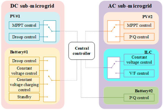
Figure 2.
Hierarchical control architecture of AC/DC hybrid microgrid.
In the DC sub-microgrid, when the DC side photovoltaic #1 is connected to the grid, in order to provide more power and make full use of solar energy resources, it generally works at maximum power point tracking (MPPT) mode [17]. During isolate island operation, the DC side photovoltaic #1 can be controlled by MPPT. However, when the generating power of the system is greater than the limit of its own consumable power, it is not suitable to work at the maximum power point. Therefore, the power-DC bus voltage () droop control is adopted to limit its power output [18]. When the DC side battery #1 is connected to the grid, the method of bus constant voltage control can be adopted to maintain the DC bus voltage stability with the interlinking converter, or it can also be charged at a constant voltage within its own tolerance. When isolating island operation, in addition to constant voltage control, the DC side battery #1 usually adopts droop control and photovoltaic #1 to regulate DC bus voltage and increase system autonomy. In addition, the state of charge () of the battery is also a key factor to be considered in the design of control strategy and to avoid overcharge or overdischarge [19].
In the AC sub-microgrid, when connected to the grid, the AC side photovoltaic #2 needs to be controlled by MPPT as well as the DC side photovoltaic #1, and the AC side battery #2 can be control charging according to its constant power (P/Q). In isolated island, when the overall power consumption of the system is low, the AC side photovoltaic #2 and battery #2 can adopt P/Q control to achieve the supply and demand balance of AC side power and reduce the working frequency of the interlinking converter.
In this paper, two parallel interlinking converters are used to exchange power between the AC and DC sub-microgrids. In the grid-connected mode, constant voltage control and DC side energy storage units are used to maintain the DC bus voltage stability. In isolated island mode, constant voltage and constant frequency (V/F) control is adopted to regulate the AC bus voltage and frequency.
3. Distribute Generation Unit Model and Lower Converter Control
3.1. Photovoltaic Power Generation Unit Model and Control Strategy
The photovoltaic cell is the smallest unit of a photovoltaic array. It is a kind of semiconductor device that uses the photovoltaic effect to convert light energy into electric energy directly [20]. When the light intensity is constant, the photo-generated current is basically constant, so it can be equivalent to a constant current source. When the photo-generated current passes through the load, the terminal voltage will be formed on the load. This voltage will cause the positive-negative (PN) junction to be forward-biased and generate the dark current that is opposite to the photo-generated current. At the same time, because the material of the photovoltaic panel itself has a certain resistivity, it is equivalent to a resistor connected in series with a constant current source. In the manufacturing process, process defects will cause leakage current of photovoltaic panels. In order to eliminate errors, parallel resistance is introduced [21]. Combined with the above analysis, the equivalent physical circuit model of the photovoltaic cell is shown in Figure 3.

Figure 3.
Physical circuit model of the photovoltaic cell.
In practical application, it is difficult to determine some parameters in the physical circuit model shown in Figure 3. Therefore, the engineering model is generally adopted [22]. Equation (1) is shown as follow:
where and are defined as:
where is the short-circuit current of the photovoltaic cell under standard test conditions, is the open-circuit voltage, is the maximum power point current, and is the maximum power point voltage.
The voltage of a single photovoltaic cell is relatively low. So, in practice application, it is often necessary to connect multiple photovoltaic units in series to form a photovoltaic array. When the output voltage and current of the photovoltaic cell are and , respectively, the output voltage and current of the photovoltaic array are expressed as:
where and are the series and parallel number of photovoltaic cells.
In this paper, both photovoltaic #1 and photovoltaic #2 use perturbation and observation method (Perturbation and Observation, P&O) to realize MPPT control [23]. This method uses a fixed step size to reduce or increase the input reference voltage of the converter, thereby moving the operating point closer to the maximum power point. Compared with other MPPT methods, the P&O method requires fewer sensors, has lower calculation complexity, and is simple to implement. The control strategy of DC side photovoltaic unit photovoltaic #1 is shown in Figure 4.

Figure 4.
The DC side photovoltaic #1 control strategy.
As can be seen from Figure 4 that in photovoltaic #1, in addition to MPPT control, in order to improve the autonomous ability or power-limited operation during isolated island operation, this paper adds droop control , which can be expressed as:
where is the DC bus measurement voltage, is the reference voltage of the DC bus, is the measured output power of the DC side photovoltaic #1, is the reference output power of the DC side photovoltaic #1, is the voltage-power droop coefficient, .
When MPPT is controlled, it may happen that the power generated by the system is greater than the maximum consumable power. In this paper, P/Q control is considered as an alternative control in the control of photovoltaic #2. The control strategy of photovoltaic power generation unit photovoltaic #2 on the AC side is shown in Figure 5.
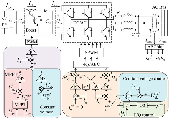
Figure 5.
The AC side photovoltaic #2 control strategy.
3.2. Battery Energy Storage Unit Model and Control
The relationship between the internal parameters of the battery is complex, and there is a nonlinear relationship between these parameters. So, the modeling of the storage battery is also the research focus of relevant experts. For the convenience of modeling, the general basic model is selected in this paper. Its physical circuit model is shown in Figure 6, which is formed by the controlled voltage source and an equivalent internal resistance in series [24].
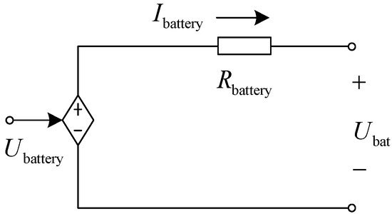
Figure 6.
General physical model for batteries.
In this paper, the “Battery” module in Matlab/Simulink is selected as the model of battery energy storage unit, and the lithium-ion (Lithium-Ion) battery model is used. When the controlled voltage source is discharged, the unload voltage is:
When the controlled voltage source is charged, the unload voltage is:
where, is the actual charge and discharge capacity of the battery, is the rated voltage of the battery, is the polarization voltage, is the battery capacity, is the voltage drop in the exponential domain, is the reciprocal of the time constant in the exponential domain.
The output voltage and are two important variables of the battery. For the general basic model, they are defined as:
where is the equivalent internal resistance of the battery.
In this paper, the battery energy storage units are connected to the AC and DC sub-microgrids. When connected to the public grid, the DC side battery mainly works with the interlinking converter to maintain the DC bus voltage stability, and the constant voltage charging is used when the battery charge is low. In the isolated island, the droop discharge is used to stabilize the DC bus voltage within a certain range. If the photovoltaic unit power generation power is greater than the power consumption, the constant voltage control charging of the DC bus is required. In addition, to protect the battery, the SOC charge and discharge threshold should be set.
The battery #1 of the DC side battery energy storage unit is connected to the DC bus through a Boost/Buck circuit, and its control strategy is shown in Figure 7.
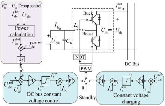
Figure 7.
The DC side battery #1 control strategy.
In Figure 7, the droop control of battery #1 can be expressed as:
where, is the DC bus measurement voltage, is the DC bus reference voltage, is the measured output power of the DC side battery #1, is the reference output power of the DC side battery #1, is the voltage-power droop coefficient. When battery #1 is in rechargeable and dischargeable mode, , . When battery #1 can only be discharged, , .
The control strategy of battery #2 in the AC side battery energy storage unit is shown in Figure 8. The voltage is boosted by the Boost/Buck circuit, then connected to the AC bus through a bidirectional DC/AC converter and filter circuit. The power instruction of the central controller is received during operation, adopting P/Q control to absorb or output power.

Figure 8.
The AC side battery #2 control strategy.
3.3. Interlinking Converter Model and Control
The interlinking converter is a key module to connect AC sub-microgrid and DC sub-microgrid. In this paper, the interlinking converter adopts a three-phase pulse width modulation (PWM) converter. In order to increase the power exchange capacity, the two converters are connected in parallel. The main circuit topology of the interlinking converter used in this paper is shown in Figure 9 [25].
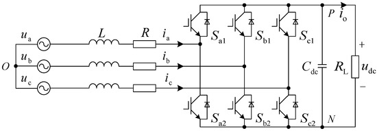
Figure 9.
Interlinking converter topology.
In this paper, the interlinking converter adopts different control strategies in grid-connected and island modes. When connected to the grid, the voltage and frequency of the AC bus are stable, so constant voltage control (unit power factor control) is adopted to maintain the DC bus voltage. In isolated island, V/F control is used to control and stabilize the voltage and frequency of the AC bus. The control strategy of a single interlinking converter in this paper is shown in Figure 10.
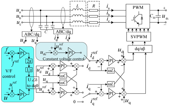
Figure 10.
Interlinking converter control strategy diagram.
4. Higher-Level Power Coordination Control Strategy
4.1. Multi-System Mode Power Coordination Control Strategy in Grid-Connected Operation
In grid-connected operation, the AC bus is directly connected to the public power grid, and its voltage and frequency will remain stable. Therefore, this section focuses on adjusting the DC bus voltage. For the DC sub-microgrid, it is necessary to maintain the power balance together with the photovoltaic power generation unit photovoltaic #1, the energy storage unit battery #1, and the interlinking converter on the DC side. In order to maximize the utilization of solar energy resources, photovoltaic power generation units will operate in MPPT mode. Besides, to maintain the DC bus voltage stability, the interlinking converter adopts DC bus constant voltage control.
To maintain the DC bus voltage, the DC side battery #1 and the interlinking converter need to work together, and the state of charge is an important factor to determine whether the battery can be charged or discharged. Therefore, the state of charge of battery #1 is taken as an important basis for the division of system mode; the maximum value is and the minimum value is . At the same time, since the photovoltaic power generation unit operates in MPPT mode, the power emitted by the DC side photovoltaic #1 is constant under steady-state, and the power absorbed by the DC load when the voltage is stable and also constant. Therefore, the balance between the two is also one of the bases for the division of system mode. The power of the DC sub-microgrid is defined as:
In addition, for the interlinking converters, the transmission direction from the AC side to the DC side is set to be positive, the maximum conversion power of a single interlinking converter is , and the maximum conversion power of two parallel converters is . Therefore, the actual conversion power of the two interlinking converters will also be referred to in the system mode division. In summary, the operation mode is analyzed according to the situation:
(1)
At this time, the DC side battery #1 has reached the maximum charged state, can only discharge. When , the DC load is not enough to consume the power generated by the DC side photovoltaic #1. In order to protect the battery, battery #1 should be in a standby state, and the excess power generated by photovoltaic #1 should be transmitted to the public grid by an interlinking converter. The power balance relationship can be expressed as:
where , the interlinking converter is in the inverter state.
When , the generation power of photovoltaic #1 on the DC side is greater than the consumption power of the load, resulting in the DC bus voltage drop. For faster adjustment to stabilize the DC bus voltage, battery #1 should be in the DC bus constant voltage mode and adjust the DC bus voltage to the rated value together with the interlinking converter. The power relationship at balancing is as follow:
where indicates the output power of battery #1 and indicates that the interlinking converter is in a rectified state.
In addition, even in the situation of grid-connection, the load power on the DC bus cannot be allowed to increase indefinitely because the interlinking converter capacity is constant. Therefore, when and , the secondary load on the DC side should be cut off to protect the normal operation of the converter.
(2)
This situation indicates that the DC side battery #1 has reached the minimum charged state and cannot continue discharging, but it can be charged. The battery should be switched to a constant voltage charging state, limiting its maximum current to be no greater than 0 and charging at rated voltage, and the power balance relationship can be expressed as:
where indicates that the DC side battery #1 absorbs power.
Although the DC side battery #1 is in constant voltage charging mode at this time, the power source is different. When , it means that although the battery power is low, the output power of the photovoltaic unit is sufficient to meet the demand of the DC load. Therefore, on the premise that the interlinking converter maintains the DC bus voltage, battery #1 can absorb the excess power generated by the photovoltaic unit at a constant voltage. When , the internal power supply of the DC sub-microgrid is scarce, but the capacity of the interlinking converter does not reach the rated value and battery #1 can still absorb power from the public grid in a constant voltage charging state. If , first put battery #1 in the standby state, and then continue to determine whether the interlinking converter is overloaded. If so, remove the DC load, otherwise, it will operate normally.
(3)
In this mode, the DC side battery #1 is in the normal range of charging and discharging. When , the running state at this time is the same as . Because battery #1 is charged at a constant voltage. Then will be greater than the minimum threshold, the power balance relationship can also be expressed as (13). When , the system running state under this condition is the same as . Because battery #1 constant DC bus voltage discharge, after a period of time, will fall below the maximum threshold, and the power balance relationship can also be expressed as (12).
Based on the above analysis, this paper divides the control strategy of the whole AC/DC hybrid microgrid system into multiple modes during grid-connected operation. The central controller needs to send commands to the lower converter in accordance with the power coordination control strategy to ensure the normal flow of power, as shown in Figure 11.
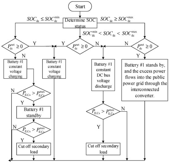
Figure 11.
Power coordination control strategy of AC/DC hybrid microgrid during grid-connected operation.
4.2. Multi-System Mode Power Coordination Control Strategy in Isolated Island Operation
In isolated island operation, the whole AC/DC hybrid microgrid system does not have the support of the public power grid, and the power balance of the entire system needs to be considered during control, so the control process is more complex than when it is connected to the grid. This paper adopts the mode of DC sub-microgrid as the main micro-grid, and the interlinking converter needs to work in the V/F control mode to maintain the voltage and frequency stability of the AC bus. In order to improve the utilization rate of solar energy, the DC side photovoltaic #1 will be in MPPT mode at the initial moment. The AC side photovoltaic #2 can work in MPPT or P/Q control mode. Moreover, the AC side energy storage unit battery #2 works in P/Q control mode. At the same time, battery #2 is regarded as an energy storage device with rated charging and discharging power, regardless of its . During operation, the control mode of battery #1 should be switched according to the power balance state. Meanwhile, the reference power of photovoltaic #2 and battery #2 should be adjusted. When the system is overloaded, the secondary load should be cut off.
Since the DC sub-microgrid is the main microgrid, the charging state of DC side battery #1 is still an important basis for operation mode analysis. The power of the hybrid AC/DC microgrid in isolated island is defined as:
where is the absorbed power of the AC load and is the output power of the AC side photovoltaic #2.
According to the operating mode in isolated island, the analysis is as follow:
(1)
The DC side battery #1 reaches the maximum power and cannot continue to charge. If , the power generated by DG in the whole microgrid system is greater than the total power consumed by the AC and DC side loads, so measures need to be taken to reduce the power generated. First, we should consider whether AC side battery #2 can be used for charging to maintain power balance. If the rated output power of battery #2 is , then battery #2 can be used to absorb excess power. At this time, set the reference power of battery #2 as:
If the AC side battery #2 cannot absorb excess power, consider adjusting the output power of the photovoltaic unit. If photovoltaic #2 is in P/Q control mode at this time, then the reference power needs to be adjusted as:
If the AC side photovoltaic #2 is in MPPT mode, then adjust the DC side photovoltaic #1 to limit power droop control. The final power balance relationship is:
When , it means that the generating power of the system micro source is not enough to maintain the normal operation of the system load. Therefore, first, the DC-side battery needs to be in droop control output power. Then, judge whether the AC side battery #2 can meet the system vacant power. If so, in order to reduce the output of battery #1, set reference (15).
If the rated power of the AC side battery #2 is , then the DC side battery #1 output power is required and its rated power is set to . If the combined output of battery #1 and battery #2 can meet the vacant power, then the system can remain stable. When , the system will be in a new equilibrium state, and the power balance relationship is:
If the joint output of the AC and DC batteries cannot meet the vacant power, the system is overloaded and the secondary load needs to be cut off.
(2)
In this state, the DC side battery #1 cannot continue to discharge. When , set battery #1 to constant voltage control mode. Due to the system power redundancy, the DC bus voltage will increase, so battery #1 will start charging. If , it means that the excess power can be absorbed into the battery within the rated power of battery #1. At this time, the power balance state can be expressed as:
In the situation of , the AC side battery #2 is also required to absorb power. When , it means that when the batteries on the AC and DC sides absorb the excess power together, the system can reach a new balance. At this time, should be set to:
where the minimum value of is 0.
When , it means that the power generated by the micro-source is too much. At this time, the processing method is the same as when . The AC side battery #2 absorbs power at rated power. When the AC side photovoltaic #2 is in P/Q mode, should be set to:
If , then the DC side battery #1 cannot continue to discharge. Therefore, it is necessary to refer to whether the AC side battery #2 can meet the vacant power of the system. If so, then set its reference power as shown in (15). If not, the secondary load needs to be cut off.
(3)
In this mode, the DC side battery #1 can both charge and discharge. When , the system running state is the same as . Conversely, when , the system running state is the same as .
In summary, the power coordination control strategy of the AC/DC hybrid microgrid when off-grid is formulated is shown in Figure 12.

Figure 12.
Power coordination control strategy of AC/DC hybrid microgrid during island operation.
5. Simulation Analysis
In order to verify the effectiveness of the power control strategy designed in this paper in the hybrid microgrid, the simulation control model as shown in Figure 1 was built in Matlab/Simulink. The basic parameters in the simulation system are shown in Table 1, in which the power is active power.

Table 1.
Basic parameters of AC/DC hybrid microgrid simulation.
5.1. Simulation of Power Control Strategy in Grid-Connected Operation
Since the AC bus is directly connected to the public power grid during the grid-connected operation, the changes of the power, voltage, frequency, and other values of the AC side microgrid are not analyzed.
(1) Case 1
When the system works in grid-connected mode, the DC side photovoltaic #1 and the AC side photovoltaic #2 work in MPPT mode. The initial of the DC side battery #1 is set to 10%, the AC side battery #2 works in P/Q control mode, and the initial is 90%. The active power of the AC load is 50 and remains unchanged. The interlinking converter works in the DC bus constant voltage control mode.
During the operation of the system, the ambient temperature remains unchanged at 25 °C, the initial light intensity is 1000 , and the DC load power is 2 . At 2 s, the light intensity was reduced to 800 . At 3 s, the DC load power increased to 8 , and at 6 s, the light intensity continued to decrease to 600 , while the DC load power continued to increase to 14 . The simulation results are shown in Figure 13.
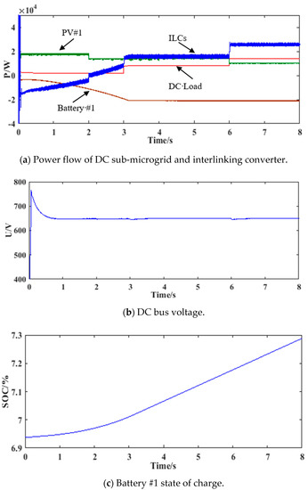
Figure 13.
System simulation curve of case 1 in grid-connected operation. (a) is the power flow of DC sub-microgrid and interlinking converter in grid-connected mode; (b) is DC bus voltage in grid-connected. (c) is the Battery #1 state of charge in grid-connected.
As can be seen from Figure 13c, at the beginning of the system operation, if the DC side battery #1 is discharged, and the state of charge will instantly fall below the minimum threshold of 10%. Therefore, the system will operate according to the situation of in Figure 11, where battery #1 will be charged at a constant voltage.
According to Figure 13a, form 0 s to2 s, the DC side photovoltaic #1 will work in the standard environment with an output power reaching 18 and the DC load power reaching 2 , resulting in . The excess power of the DC sub-microgrid will be absorbed by the DC side battery #1, but its charging power will not reach the maximum value soon, and the battery charging current will increase slowly. Therefore, the power flowing to the large power grid through the interlinking converter gradually decreases. From 2 s to 3 s, the light intensity decreases, and the output power of DC side photovoltaic #1 is about 14 . At this time, the load power remains unchanged, and the charging power of DC side battery #1 continues to increase, so the power transmitted from the interlinking converter to the public grid is getting less and less. At 2.5 s, the power of the interlinking converter changes from negative to positive, and the power generated by DC side photovoltaic #1 is not enough to maintain battery #1 charging and load consumption. From 3 s to 6 s, the light intensity is unchanged, and the load power is increased to 8 . At 3.2 s, the charging power of battery #1 on the DC side reaches the maximum value, about 21 , so the power of the interlinking converter is also stable at about 15 . From 6 s to 8 s, the DC load power continues to increase to 14 , while the DC side photovoltaic #1 output power decreases to 10 , resulting in . Furthermore, the power of DC side battery #1 is still below the minimum threshold and continues to be charged at a constant voltage. At this time, the absorbed power of the DC sub-microgrid is mainly provided by the interlinking converter from the public power grid, and about 25 , which does not reach its maximum transmission power.
Figure 13b shows the DC bus voltage fluctuations, from which it can be seen that the voltage is stable at the rated value of 650 V at about 0.8 s. Due to the change of system power, there is a slight fluctuation at 2 s, 3 s, and 6 s, but the rated value is quickly restored.
(2) Case 2
When the temperature is kept at 25 °C and the light intensity is kept at 1000 , the system is connected to the grid, and the DC side photovoltaic #1 and AC side photovoltaic #2 work in MPPT mode. The initial of DC side battery #1 is set to 95%. The initial conditions of AC side battery #2, interlinking converter, and AC load are the same as in case 1. At the initial moment of the system, the DC load power is 10 . At 3 s, the DC load power increases to 18 . At 6 s, the DC load continues to increase, and the power reaches 28 . According to the system setting, the charge state of DC side battery #1 is above the maximum threshold of 90% at this time, so the system will operate as when connected to the grid. The simulation results are shown in Figure 14.
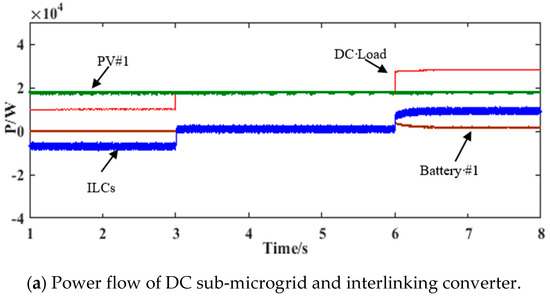
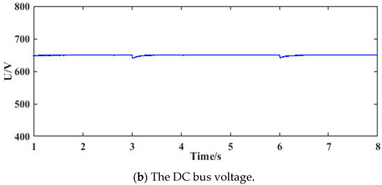
Figure 14.
System simulation curve of case 2 in grid-connected operation. (a) is the power flow of DC sub-microgrid and interlinking converter in grid-connected mode; (b) is DC bus voltage in grid-connected.
As can be seen from Figure 14a that form 1 s to 3 s, the DC side photovoltaic #1 works under standard conditions, the output power reaches a maximum value of 18 , while the DC load power remains unchanged at 10 , that is, . However, the internal of the DC side battery #1 has exceeded the maximum threshold, so it cannot continue to charging, that is, it is in a standby state and the output power of 0 . All the excess power in the DC sub-microgrid is transmitted from the interlinking converter to the AC side, and the transmission power is −8 . From 3 s to 6 s, when the DC load power is increased to 18 , the power generation of DG in the DC sub-micro grid is just enough to meet the power consumption of the load, . So, the transmission power of DC side battery #1 and the interlinking converter is 0 . From 6 s to 8 s, the DC load power continues to increase by 10 to 28 . At this time, the output power of DC side photovoltaic #1 cannot meet the DC load, then . The DC side battery #1 switches from standby mode to constant voltage mode to maintain the DC bus voltage with the interlinking converter and the output power is 2 . The transmitted power of the interlinking converter is 8 .
According to Figure 14b, the DC load power will increase at 3 s and 6 s, and the DC bus will decrease slightly. However, due to the constant voltage control of DC side battery #1 and the interlinking converter, the system quickly reaches a power balance state. As a result, the DC bus voltage will quickly stabilize to the rated value.
5.2. Simulation of Power Control Strategy in Isolate Island Operation
During the island operation, the overall power balance should be considered. At this time, the interlinking converter works in V/F control mode to provide voltage and frequency support for the AC bus.
(1) Case 1
The system works in island mode with a constant temperature of 25 °C, the DC side photovoltaic #1 works in MPPT mode, and the AC side photovoltaic #2 works in P/Q mode. The AC side photovoltaic #2 active power reference value is set to 16 , and the reactive output is set to 0 . The of DC side battery #1 and AC side battery #2 are both 85%, they operate in mode in Figure 12. The DC load power is 10 , and the AC load active power is 20 . At the initial moment, the light intensity was 1000 . At 5 s, the light intensity decreased to 800 . The simulation results of active power flow in the system are shown in Figure 15.
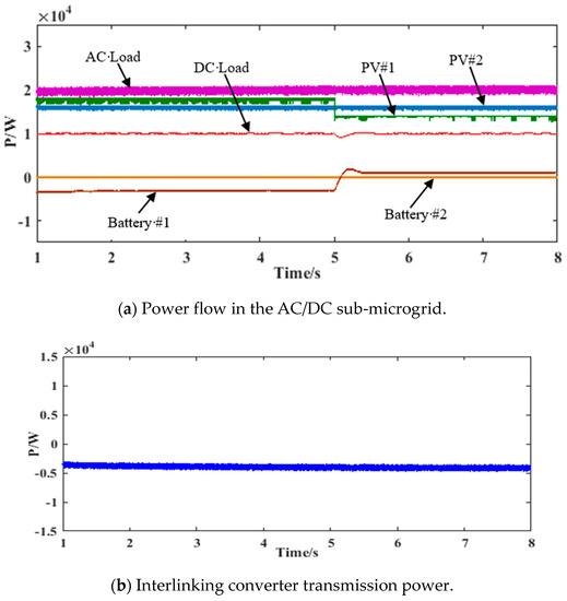
Figure 15.
System simulation curve of case 1 in isolated island operation. (a) is the overall power flow of AC/DC sub-microgrid in island mode; (b) is the transmission power of interlinking converters in island mode.
As can be seen from Figure 15a that at the beginning of the system operation, the output power of DC side photovoltaic #1 reached 18 under standard conditions, and the output power of AC side photovoltaic #2 is 16 , which is 34 in total. At this time, the sum of the active power of AC load and DC load is 30 , then . According to Figure 12, the DC side battery #1 works in constant voltage mode and can absorb the excess power of the system. Therefore, the active power reference value of AC side battery #2 is 0 , and the absorbed power of DC side battery #1 is about 3 . Form 5 s to 8 s, the light intensity is reduced, and the output of DC side photovoltaic #1 is reduced to 14 , then . Therefore, the active power reference value of AC side battery #2 is still 0 . However, due to system losses, DC side battery #1 still needs to maintain a power output of approximately 1 to stabilize the system.
The AC bus voltage and frequency curves are shown in Figure 16a,b, and the DC bus voltage curve is shown in Figure 16c.
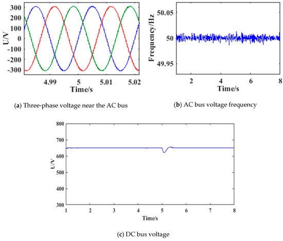
Figure 16.
System simulation curve of bus voltage and frequency for case 1 in the island operation. (a) is the three-phase voltage interception part of AC bus in island mode; (b) is the frequency interception part of AC bus voltage in island mode; (c) is the DC bus voltage in island mode.
According to Figure 16a,b, the voltage and frequency of the AC bus do no obviously fluctuate during 5 s, and the rated value is always maintained during system operation. As can be seen from Figure 16c, the DC bus voltage is maintained at the rated value of 650 V from 1 s to 5 s. At 5 s, due to the sudden decrease in light intensity, the output of DC side photovoltaic #1 will immediately decrease, while the DC side battery #1 will not immediately reduce its absorbed power. Therefore, the DC bus voltage will have a downward trend. When it falling to 622 V, the DC side battery #1 no longer absorbs power, so the DC bus voltage immediately returns to the rated value.
(2) Case 2
The system works in island mode, the ambient temperature is 25 °C, the light intensity is 1000 , and the DC side photovoltaic #1 runs in MPPT mode. Moreover, the AC side photovoltaic #2 runs in P/Q mode, with the active power constant at 16 and reactive power output at 0. The settings of the DC side battery #1 and the AC side battery #2 are the same as that of isolated island in case 1. At the initial moment, the DC load power is 20 , the AC load active power is 50 , and the reactive power is 0 . At 3 s, the active power of the AC load increases to 55 . At 6 s, the active power of the AC load continues to increase until it reaches 60 . The system active power flow simulation waveform is shown in Figure 17.

Figure 17.
System simulation curve of active power flow in case 2 in island operation. (a) is the overall power flow of AC/DC sub-microgrid in island mode; (b) is the transmission power of interlinking converters in island mode.
As can be seen from Figure 17a that at the initial moment of the system, the output power of the DC side photovoltaic #1 reaches a maximum value of 18 , and the actual output power of the AC side photovoltaic #2 is lower than the theoretical value, which is about 29 . The sum of the active power of the DC load and the AC load reaches 70 , that is, . So, the DC side battery #1 is droop control. At the same time, the active power deficit exceeds the rated power of AC side battery #2, so battery #2 maintains the rated power output of 10 , and the AC side is still unbalanced. As shown in Figure 17b, about 11 of active power is transmitted from the DC side to the AC side through the interlinking converter. At this time, in order to balance the power balance of the DC sub-microgrid and the AC sub-microgrid, the DC side battery #1 power output is about 14 .
At 3 s, the active power of the AC load increases to 55 , remains unchanged, and the active power deficit increases. However, the DC side battery #1 and the AC side battery #2 still do not reach their rated output power, so they can continue to maintain the system balance. At this time, the DC side battery #1 output power is about 19 .
At 6 s, the active power of the AC load continues to increase by 5 and the DC side battery #1 reaches the rated output power is still not enough to maintain the system balance. Therefore, it is necessary to cut off the secondary load of 10 on the DC side. The load power on the DC side is reduced to 10 , and the DC side battery #1 output power is about 14 . Meanwhile, according to Figure 17b, the power entering the AC sub-microgrid is about 21 . The DC bus voltage in this mode is shown in Figure 18.
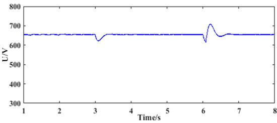
Figure 18.
System simulation curve of DC bus voltage in case 2 during island operation.
As can be seen from Figure 17a that at 3 s, the active power of the AC load increases, and the DC side battery #1 will not be discharged to the power balance state immediately. Therefore, at 3 s in Figure 18, the DC bus will drop to about 620 V and then rise back to the rated voltage of 650 V, the system power balance. At 6 s, the DC bus voltage will decrease due to the continuous increase of AC load active power. However, when the whole AC/DC microgrid system is overloaded, the secondary load of 10 kW on the DC side will be cut off. At this time, because the output of DC side battery #1 will not change immediately, the DC bus voltage will rise to 705 V, and then it will drop to the rated voltage. In the whole process, the deviation of the DC bus voltage is within ±10%, which meets the requirements of allowable deviation of power quality supply voltage [26].
6. Conclusions
In this paper, the operation mode of the AC/DC hybrid microgrid is analyzed in detail, and the power coordinated control strategy of grid-connected operation and island operation is designed. In grid-connected operation, it is based on the control of the interlinking converter of the DC bus constant voltage. To stabilize the DC bus voltage, adjust the operating mode of DC energy storage and control the on-off of secondary loads by referring to the charged state of DC energy storage, the power balance state of DC microgrid, and the maximum transmitted power of interlinking converters. In the island operation, DC sub-microgrid is the main microgrid, DC energy storage is the main power regulation equipment, and based on the principle of “energy is in short supply in the system, DC energy storage finally discharge, energy supply exceeds demand in the system, DC energy storage gives priority to charging” of DC energy storage. In order to maintain the balance of the overall power, the control strategy of the micro-source, the reference power, and the on-off of the secondary load should be adjusted by referring to the charged state of DC energy storage, the overall power balance state of the system, and the operation mode of each micro-source. Finally, the higher control, analysis, and integration of system data and reasonable control of each converter control strategy change make the reliable and stable operation of the system. The lower control integrates various control strategies of the converter, improves the flexibility of the system, realizes the reasonable distribution of power under different modes, and reduces the consumption of energy.
In this paper, the switching mode of the bidirectional converter mode is carried out under ideal conditions without considering the switching dynamics. At the same time, system design is a steady-state process, and the study of the transient process will become our research direction in the following steps.
Author Contributions
Conceptualization, Z.H. and G.W.; methodology, G.W. and Z.H.; software, G.W.; validation, G.W., Z.H., F.W., and X.W.; formal analysis, G.W.; investigation, Z.H.; resources, X.W. and F.W.; data curation, X.W. and F.W.; writing—original draft preparation, G.W.; writing—review and editing, X.W. and F.W.; visualization, G.W.; supervision, Z.H.; project administration, X.W. and F.W. All authors have read and agreed to the published version of the manuscript.
Funding
The research received no external funding.
Acknowledgments
We gratefully acknowledge the technical assistance of DL850E ScopeCorder.
Conflicts of Interest
The authors declare no conflict of interest.
References
- Li, X.L.; Li, Z.W.; Guo, L.; Huang, D.; Li, P.F.; Zhu, J.B.; Wang, C.S. Flexible Control and Stability Analysis of AC/DC Microgrids Clusters. Chin. Soc. Electr. Eng. 2019, 39, 5948–5961. [Google Scholar]
- Alrajhi Alsiraji, H.; El-Shatshat, R. Serious Operation Issues and Challenges Related to Multiple Interlinking Converters Interfacing a Hybrid AC/DC Microgrid. In Proceedings of the 2018 IEEE Canadian Conference on Electrical and Computer Engineering (CCECE), Quebec City, QC, Canada, 13–16 May 2018; pp. 1–5. [Google Scholar]
- Wang, J.J.; Jin, C.; Wang, P. A Uniform Control Strategy for the Interlinking Converter in Hierarchical Controlled Hybrid AC/DC Microgrids. IEEE Trans. Ind. Electron. 2018, 65, 6188–6197. [Google Scholar] [CrossRef]
- Li, P.; Guo, T.Y.; Zhou, F.Q.; Yang, J.X.; Liu, Y. Nonlinear Coordinated Control of Parallel Bidirectional Power Converters in an AC/DC Hybrid Microgrid. Int. J. Electr. Power Energy Syst. 2020, 122, 106208. [Google Scholar] [CrossRef]
- Karlsson, P.; Svensson, J. DC Bus Voltage Control for a Distributed Power System. IEEE Trans. Power Electron. 2003, 18, 1405–1412. [Google Scholar] [CrossRef]
- Dragičević, T.; Vasquez, J.C.; Guerrero, J.M.; Škrlec, D. Advanced LVDC Electrical Power Architectures and Microgrid: A Step Toward a New Generation of Power Distribution Networks. IEEE Electrif. Mag. 2014, 2, 54–65. [Google Scholar] [CrossRef]
- Anand, S.; Femandes, B.G.; Guerrero, J.M. Distributed Control to Ensure Proportional Load Sharing and Improve Voltage Regulation in Low-voltage DC Microgrid. IEEE Trans. Power Electron. 2013, 28, 1900–1913. [Google Scholar] [CrossRef]
- Prodanovic, M.; Green, T.C.; Mansir, H. Survey of Control Methods for Three-phase Inverters in Parallel Connection. IEEE Conf. Publ. 2000, 475, 472–477. [Google Scholar]
- Mazumder, S.K.; Tahir, M.; Acharya, K. Master-slave Current-sharing Control of a Parallel DC-DC Converter System Over an RF Communication Interface. IEEE Trans. Ind. Electron. 2008, 55, 59–66. [Google Scholar] [CrossRef]
- Simpson-Porco, J.W.; Shafiee, Q.; Dörfler, F.; Vasquez, J.C.; Guerrero, J.M.; Bullo, F. Secondary Frequency and Voltage Control of Islanded Microgrids Via Distributed Averaging. IEEE Trans. Ind. Electron. 2015, 62, 7025–7038. [Google Scholar] [CrossRef]
- Wang, H.Y.; Zhou, Z.C.; Yuan, Q.F.; Bao, W.; He, G.Q.; Li, G.H.; Feng, K.H. A hierarchical control of microgrid based on droop controlled voltage source converter. In Proceedings of the Asia-Pacific Power and Energy Engineering Conference, Hong Kong, China, 8–11 December 2013; pp. 1–4. [Google Scholar]
- Pequito, S.; Kar, S.; Agbi, C.; Aguiar, A.P.; Popli, N.; Ilić, M. Designing Decentralized Control Systems Without Structural Fixed Modes: A Multilayer Approach*. In Proceedings of the 4th IFAC Workshop on Distributed Estimation and Control in Networked System, Koblenz, Germany, 25–26 September 2013; pp. 81–88. [Google Scholar]
- Kondratiev, L.; Dougal, R.; Veselov, G.; Kolesnikov, A. Hierarchical Control for Electromechanical Systems Based on Synergetic Control Theory. In Proceedings of the IEEE International Conference on Contrla Applications, Saint Petersburg, Russia, 8–10 July 2009; pp. 495–500. [Google Scholar]
- Marinovici, L.D.; Lian, J.; Kalsi, K.; Du, P.; Elizondo, M. Distributed Hierarchical Control Architecture for Transient Dynamics Improvement in Power System. IEEE Trans. Power Syst. 2013, 28, 3065–3074. [Google Scholar] [CrossRef]
- Lin, P.; Jin, C.; Xiao, J.; Li, X.; Shi, D.; Tang, Y.; Wang, P. A Distributed Control Architecture for Global System Economic Operation in Autonomous Hybrid AC/DC Microgrids. IEEE Trans. Smart Grid 2019, 10, 2603–2617. [Google Scholar] [CrossRef]
- Feng, W.; Sun, K.; Guan, Y.; Guerrero, J.M.; Xiao, X. Active Power Quality Improvement Strategy for Grid-connected Microgrid Based on Hierarchical Control. IEEE Trans. Smart Grid 2018, 9, 3486–3495. [Google Scholar] [CrossRef]
- Agrawal, A.; Gupta, R. Distributed Coordination Control of Hybrid Energy Resources for Power Sharing in Coupled Hybrid DC/AC Microgrid Using Paralleled IFCs/ILCs. IET Smart Grid 2019, 2, 89–105. [Google Scholar] [CrossRef]
- Peyghami, S.; Mokhtari, H.; Blaabjerg, F. Autonomous Operation of a Hybrid AC/DC Microgrid with Multiple Interlinking Converters. IEEE Trans. Smart Grid 2018, 9, 6480–6488. [Google Scholar] [CrossRef]
- Ma, T.; Cintuglu, M.H.; Mohammed, O.A. Control of a Hybrid AC/DC Microgrid Involving Energy Storage and Pulsed Loads. IEEE Trans. Ind. Appl. 2017, 53, 567–575. [Google Scholar] [CrossRef]
- Panibase, V.R.; Nanavala, H.B. A Review of PV Technology Power Generation, PV Material, Performance and Its Applications. In Proceedings of the 2017 International Conference on Inventive Systems and Control (ICISC), Coimbatore, India, 19–20 January 2017; pp. 1–5. [Google Scholar]
- Zhou, D.J.; Zhao, Z.M.; Wu, L.B. Analysis characteristics of photovoltaic arrays using simulation. J. Tsinghua Univ. 2007, 47, 1109–1112, 1117. [Google Scholar]
- Yang, Y.P.; Yang, Y.; Wang, J.S.; Zhang, G.H. Simulation of Battery Maximum Power Tracking Control for Photovoltaic Power Generation System. Comput. Simul. 2018, 35, 116–121. [Google Scholar]
- Noor, S.Z.M.; Omar, A.M.; Radzi, M.A.M.; Mahzan, N.N. Signal Stage String Inverter for Grid-connection Photovoltaic System with Modified Perturb and Observe(P&O) Fuzzy Logic Control (FLC)-Based MPPT Technique. J. Electr. Syst. 2016, 12, 344–356. [Google Scholar]
- Ding, M.; Tian, L.G.; Pan, H.; Zhang, X.; Zhou, J. Research on control strategy of hybrid AC/DC microgrid. Power Syst. Prot. Control. 2015, 43, 1–8. [Google Scholar]
- Lei, M.Y.; Zhang, Y.; Meng, L.X.; Wang, Y.; Yang, Z.; Cao, D. A Novel Adaptive Model Predictive Control Based Three-phase Inverter Current Control Method. Appl. Sci. 2019, 9, 5413. [Google Scholar] [CrossRef]
- Zhang, B.F.; Cao, G.D.; Ren, C.G.; Wang, J.; Han, X. Autonomous Control Strategy of Bidirectional AC/DC Converter in Low Voltage Hybrid Microgrid. In Proceedings of the 2017 12th IEEE Conference on Industrial Electronics and Applications (ICIEA), PhumKasekum, NR6, Siem Reap, Cambodia, 18–20 June 2017; pp. 1564–4569. [Google Scholar]
Publisher’s Note: MDPI stays neutral with regard to jurisdictional claims in published maps and institutional affiliations. |
© 2020 by the authors. Licensee MDPI, Basel, Switzerland. This article is an open access article distributed under the terms and conditions of the Creative Commons Attribution (CC BY) license (http://creativecommons.org/licenses/by/4.0/).