Article

A Novel Precipitate-Type Architected Metamaterial Strengthened via Orowan Bypass-Like Mechanism

1
School of Physics Science and Engineering, Tongji University, Shanghai 200092, China
2
School of Materials Science and Engineering, Tongji University, Shanghai 200092, China
3
Shanghai Key Laboratory for R&D and Application of Metallic Functional Materials, Shanghai 201804, China
4
Shanghai Zhichi Intelligent Technology Co., Ltd., Shanghai 200083, China
*
Author to whom correspondence should be addressed.
Appl. Sci. 2020, 10(21), 7525; https://doi.org/10.3390/app10217525
Submission received: 28 September 2020 / Revised: 21 October 2020 / Accepted: 22 October 2020 / Published: 26 October 2020
(This article belongs to the Special Issue Computational Methods for Fracture Ⅱ)

Abstract

:
The objective of the study is to investigate the strengthening mechanism of embedded meta-precipitates in the design of architected metamaterials. Four precipitate-type architected metamaterials are designed and prepared by fused deposition modelling (FDM). The difference of mechanical properties and deformation mode of these structures is analyzed. The strengthening effect of the introduced meta-precipitates is then compared with Orowan bypass strengthening mechanism. The similarities and discrepancies of metallurgical hardening principles and that found in architected metamaterials are established. It is found that due to the introduction of embedded meta-precipitates, the deformation of the structure changes significantly from diagonal crushing to a meander route, thus improves the mechanical properties and energy absorption abilities. The hindering effect and the influence of volume fraction of meta-precipitates is similar to Orowan bypass mechanism.

1. Introduction

Architected metamaterials represent a class of artificially-designed materials that consist of periodically arranged microstructures [1]. Desirable properties can be implemented in architected metamaterials that previously unachievable in conventional solids [2], such as ultra-lightweight [1,3], excellent energy absorption [4], negative Poisson’s ratio [5] and heat dissipation [6]. Consequently, this novel group of materials has been receiving considerable attention as structural materials for a myriad of applications in the industry of aerospace [7] and medicine [8]. At present, the rapid development of additive manufacturing (AM) technologies opens up the possibilities of fabricating metamaterials with complex microstructures and unmatched capabilities [9,10].
The architecture of the unit cells (the thickness and configuration of struts, geometry, etc.) plays a significant role in the mechanical performance of architected metamaterials [2]. Typical 2D and 3D unit cell structures can be divided into stretching-dominated and bending-dominated lattices [11]. While the former such as Octet and Octahedral lattices exhibits higher strength and stiffness, the latter is suitable for energy absorption [12]. To meet the demand of various applications, a great deal of unit cell structures has been designed and investigated.
Extensive attention has been recently paid to the prime properties of architected metamaterials with periodic arrangement of struts (similar to atomic bonds) and nodes (equivalent to atoms), which are constructed to mimic the microstructure of perfect metals/alloys. Typical examples are: simple cubic structure (SC), face-centered cubic structure (FCC) and body-centered cubic structure (BCC) [13]. Ushijima et al. [14] have conducted a theoretical analysis to predict the initial stiffness and plastic collapse strength of architected metamaterial with a BCC structure, which illustrated a nonlinear relationship between plastic collapse strength and strut aspect ratio. Dejean and Mohr [15] have designed elastically-isotropic truss lattices through a combination of SC, BCC and FCC structures, and a theoretical limit of stiffness could be achieved at the cost of a 40% reduction of theoretical Young’s modulus due to periodic homogenization. Jin et al. [16] have conducted both dynamic experiments and numerical simulations on metallic BCC structures, and figured out that the strength and energy absorption capability are proportional to the square of relative density.
Several unit-cell-based topology optimization methods for architected metamaterials are proposed to help fabricate metamaterial structures with designed properties. Schaedler et al. [3] have fabricated ultralightweight metallic metamaterial with nickel-plating thin film, thus improved mechanical efficiency was obtained via optimizing dimensions of the architecture. Trifale et al. [17] have presented a systematic unit cell design methodology to generate micro-architected structures and a 12% higher thermal conductivity was achieved by optimizing the connectivity of struts while maintaining the periodicity. Gu et al. [18] have proposed an optimization method with the combination of structural topology and material chemistry for the Octet structure, and found the proper unit cell size and relative density for attaining optimal strength of Cu micro-lattice. Although highly unusual thermal or mechanical properties can be obtained by appropriate design and optimization of the unit cell architecture [17], marginal improvement has been made on the connectivity among the unit cells. In other word, research work has been limited to the architected metamaterials with periodically-distributed lattices.
Various base materials are applied to prepare such architected metamaterials, such as polymers [19], metals [3,18] or ceramics [20]. The mechanical response is to a large extent influenced by the base material since different materials exhibits different strength or work-hardening behavior [21]. However, it is commonly found in architected metamaterials with different materials and microstructures that periodic arrangement of struts and nodes make them fail along the particular direction [22,23]. Consequently, they suffer an obvious reduction of strength under external loads due to the presence of shear bands and deformation localization [23,24], which indicates the inefficiency and reduced performance in energy absorption applications.
To solve this problem, two aspects of approaches have been recently proposed: (a), one is to improve the manufacturing process, such as employing post-manufacture heat treatment [22], or optimizing process parameters [23]; (b), the other is to modify the structural configuration, such as orientation change [25] or beam shape modification [26]. However, the improvement of manufacturing process is so far focused only on metallic materials, and at the cost of strength reduction [22]. Comparatively, structural modification is more effective in improving energy absorption capability at the same time maintaining higher strength, while it is still restricted to the architected metamaterials with perfect periodicity.
From another perspective, the failure along particular direction and the formation of shear band in architected metamaterials with perfect periodicity is similar to the slip activity along defined directions and to the rapid stress reduction in single crystals [27,28]. However, in polycrystals, other features (such as grain boundaries or precipitates) serve as obstacles to strain localization and slip activity [29,30]. Due to the similarity of mechanical responses between single crystals and periodically-arranged lattice structures, Pham et al. [31] have supposed that hardening principles that similar to those found in polycrystals are applicable to architected metamaterials, and some of them (grain boundary hardening, multi-phase hardening, etc.) have been verified.
However, research efforts have not yet been focused on the detailed comparison of the hardening mechanism between metallurgy and architected metamaterials. The similarities and discrepancies of the deformation behavior and the mechanical responses of crystalline materials and architected metamaterials remain unknown. These problems hinder research efforts to solve the “rapid failure” problem by changing the periodic arrangements of unit cells, as well as establish a systematic strengthening theory in architected metamaterials of such design.
Herein, we limit our attention to the precipitate-type architected metamaterials that mimic the crystallographic microstructures of precipitation-hardened alloys. The architected metamaterials are constructed by repeating a 2D geometry on the out-of-plane direction. In-plane mechanical properties and deformation behavior of these structures under compression are investigated in detail to figure out the effect of such design. The deformation mode and strengthening effect are then compared to those of precipitation-hardened alloys. General disciplines of the similarities and discrepancies between Orowan hardening mechanism and the strengthening effect found in architected metamaterials are summarized, which validates our attempt to integrate metallurgical hardening principles into unit cell design.

2. Materials and Methods

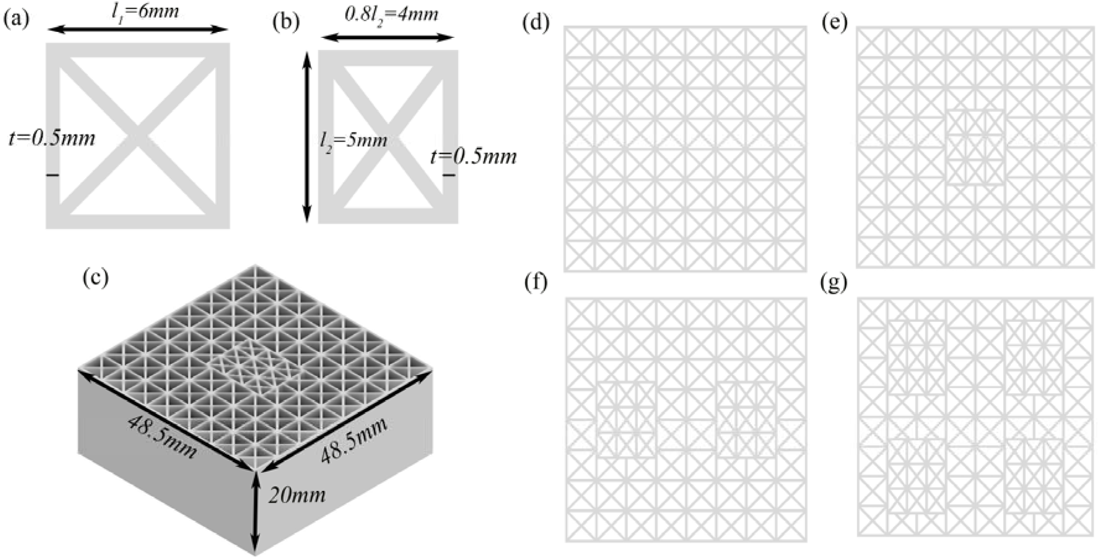
2.1. Design Methodology

In the present work four structures of the precipitate-type architected metamaterial are studied. The structural modification is focused on 2D geometry, and the structure is constructed by repeating the 2D lattice on the out-of-plane direction. The term “precipitate-type” is employed to describe the particular design of architected metamaterial which uses for reference the precipitation hardening mechanism found in crystalline materials. Precipitates are mimicked by embedding lattices (meta-precipitates) into the original matrix. The structure which consists of completely periodic arrangement of unit cells without any precipitates (P-0 structure) is created to be a baseline in the study, and precipitate-type models are also generated with 1,2 and 4 embedded meta-precipitates (P-1, P-2 and P-4 structure, respectively), as shown in Figure 1d–g. The four structures we design have eight repeated unit cells in both horizontal and transverse direction to avoid size effect [32]. The thickness on the out-of-plane direction of each design is 20mm. The out-of-plane deformation is avoided under the condition of the defined parameters.
The unit cell (matrix) is designed to connect in a diagonal manner to mimic atomic bonds of BCC structures in a 2D model, with the strut width of 0.5 mm and lattice parameter of 6 mm × 6 mm. The meta-precipitates exhibit different parameter in triangular shapes with a side-to-height ratio of approximately 1.5:1, which is accordance to microstructural configuration of precipitates [33]. The detailed parameter is shown in Figure 1a–c.

2.2. Relative Density

The relative density of the designed architected metamaterials can be controlled by the thickness of cell walls. The relative density ρ * ρ s , defined as the ratio of the actual density of the samples and that of the base material, is controlled by the strut width-to-length ratio t / l , and can be summarized as [34]:
ρ * ρ s = m ( t l ) n ( t l ) 2
where for the matrix, the cubic correction coefficient m = 4.83 and n = 5.83, and for the meta-precipitate, m = 5.20 and n = 6.76, which are obtained by undetermined coefficient method, and fit well with the computer aided design (CAD) calculations when different width-to-length ratio is applied. By Equation (1), the relative density of hybrid structure (containing both matrix and meta-precipitate) can be written as:
ρ * ρ s = ( 1 8.2 % n ) [ 4.83 ( t l 1 ) 5.83 ( t l 1 ) 2 ] + 8.2 % n [ 5.20 ( t l 2 ) 6.76 ( t l 2 ) 2 ]
where n represents the number of meta-precipitates. l 1 and l 2 represents the unit cell parameter of matrix and meta-precipitate, respectively, as shown in Figure 1a,b. By Equation (2), the relative density of the four structures are 0.34, 0.35, 0.36 and 0.38, respectively.

2.3. Sample Preparation

The specimens for each designed architected metamaterial are produced using fused deposition modeling (FDM) process of additive manufacturing (3D printing) technology, due to its merits of economy and efficiency. See Ref. [35,36] for more information about FDM process. The 3D printer used to manufacture these samples is the I3 Mega printer (Anycubic Co, Ltd.) with the build material poly lactic acid (PLA+) polymer. The printing resolution is set to be 0.2 mm and the thickness of each strut for all samples is 0.5 mm. The nozzle temperature is set to be 200 °C and the bottom plate 60 °C. The CAD models of the samples are first created by Inventor 2019 and then input into the 3D printer software Simplify3D for printing path planning. Single filament is used for each strut to avoid strength or stiffness reduction and poor connection of adjacent filaments, which is commonly observed in traditional multi-filaments FDM process [37]. Single filament process can be guaranteed by the reasonable settings of nozzle diameter and extrusion rate. The nozzle diameter is controlled to be 0.08mm with the extrusion rate of 2 in experiments. The actual strut thickness of the 3D-printed samples is then checked using microscopic image processing software. Due to the limitation of the 3D printer, a slight deviation of strut thickness and relative density is observed and shown in Table 1, which is mainly caused by the printing process [38].

2.4. Quasi-Static Compression Experiment

The quasi-static compression experiment is carried out using an CMT5105 machine (100 KN) at room temperature to study the mechanical property of architected metamaterial, according to the national standard GB/T 31930-2015. The specimens are compressed along the Z direction with the crosshead speed of 5mm/min. Force-displacement curve is generated and recorded during the compression for further analysis. A video camera (Huawei) is utilized to capture the deformation mode and corresponding failure of the samples during compression experiment. A total of 12 samples (3 samples for each structure) are compressed to ensure the reproducibility of deformation behavior and stress-strain curve. The energy absorption U V , Specific energy absorption U M and energy absorption efficiency η are calculated with the equations proposed in Ref. [34,39].

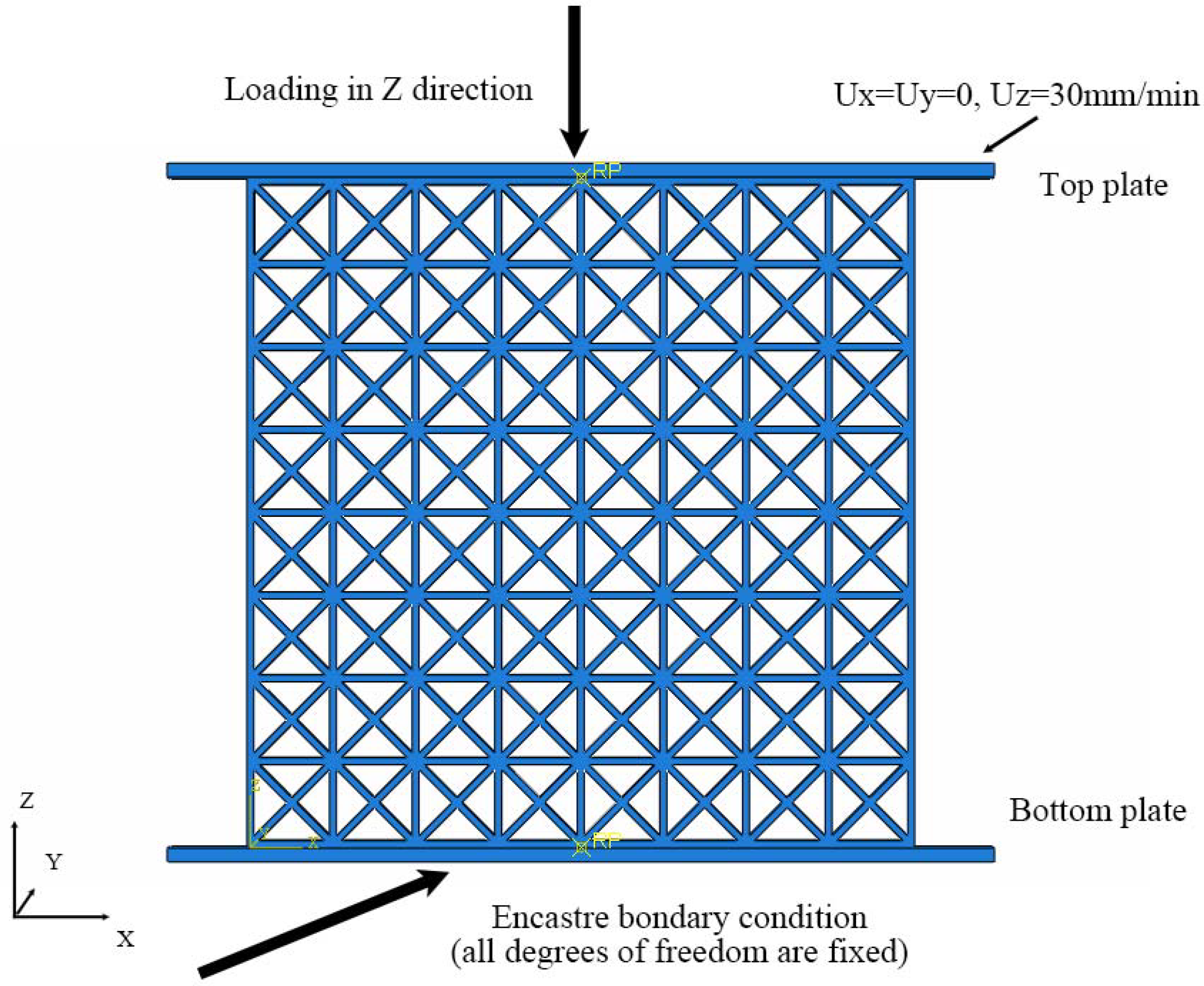
2.5. Finite Element (FE) Simulation

The Explicit solver of commercial software ABAQUS 2019 is used for FE simulation of the architected metamaterial under quasi-static compression. The dimension of the model is the same as that of 3D-printed specimen. The model is placed between two rigid-body plates which are established to simulate the top and bottom compression platforms during the experiment. The bottom plate is completely fixed underneath the model with an encastre boundary condition, whereas the top plate is set to move along the Z direction at the velocity of 5mm/min. The boundary conditions are illustrated in Figure 2. The out-of-plane deformation is constrained. The General Contact algorithm is applied as the interaction property of the model with both tangential and normal behavior. A penalty friction coefficient of 0.2 as well as a hard pressure-overclosure contact are defined. The mesh of the model is generated using eight-node linear reduced-integration element(C3D8R) with an average element size of 0.25 mm. The model geometry is large when compared to the element size. The element quality analysis tool is applied which indicates no errors or warning elements. The displacement and reaction force of the top plate are recorded to generate stress-strain graphs. A combination of ductile damage and shear damage is employed to simulate damage evolution of any element. The prime properties of the selected material poly lactic acid (PLA+) are summarized in Table 2.

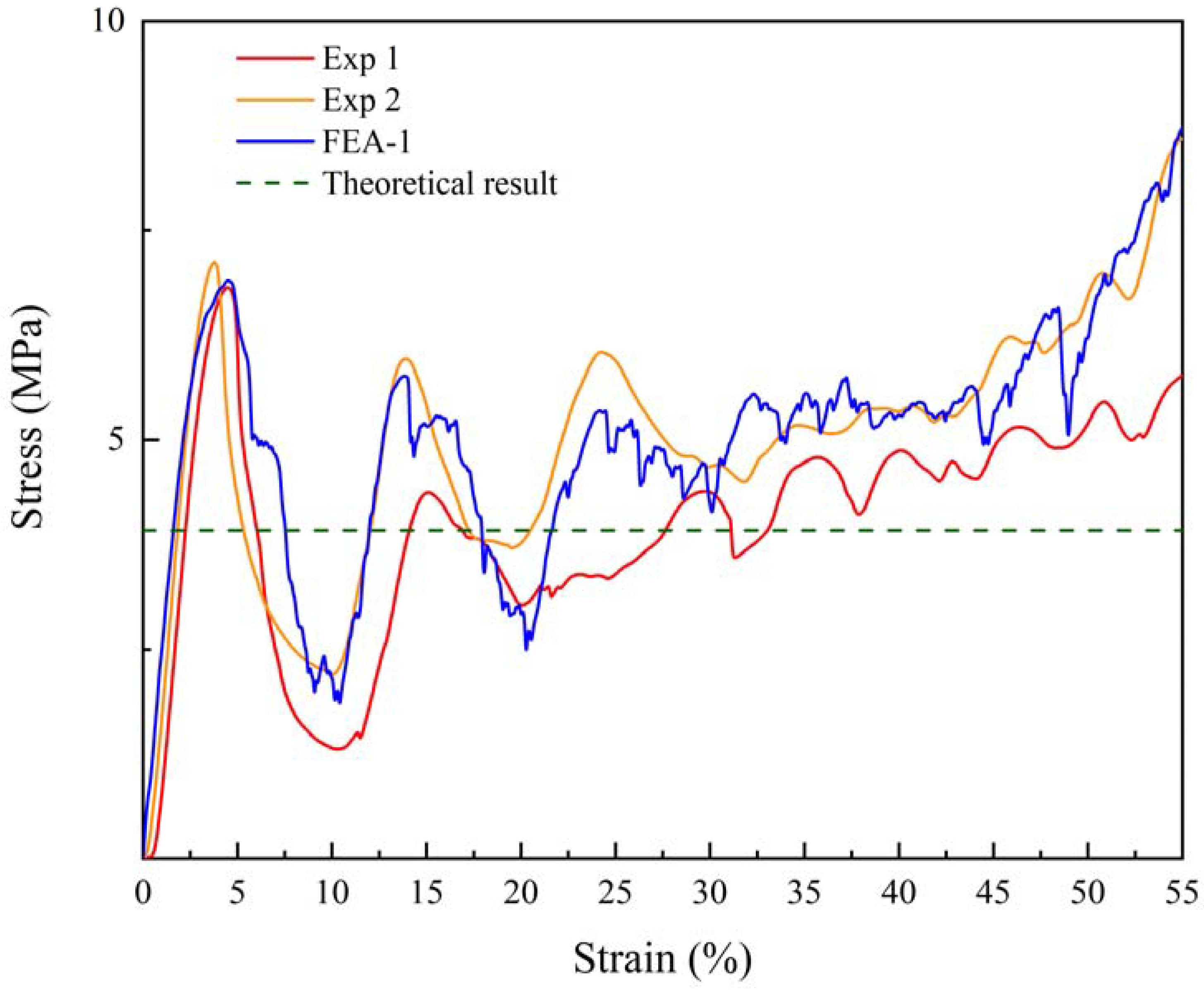
2.6. Verifications of FE Model

The stress-strain curve of the standard hexagonal honeycomb during the simulation is compared with the experiment results and the theoretical calculations, in order to validate the accuracy of the FE simulation. Figure 3 shows two experiment results and one FE prediction curve. There is negligible difference between them. The horizontal dashed line in Figure 3 represents the theoretical value of plateau stress for hexagonal honeycomb with the same size. The plateau stress of the experiment results and the FE prediction is further measured by averaging stress value when the strain is in the range of 0.2–0.4. The relative error is calculated as shown in Table 3, with the value of approximately 5.04%, demonstrating the effectiveness and accuracy of the FE simulation settings.

3. Results

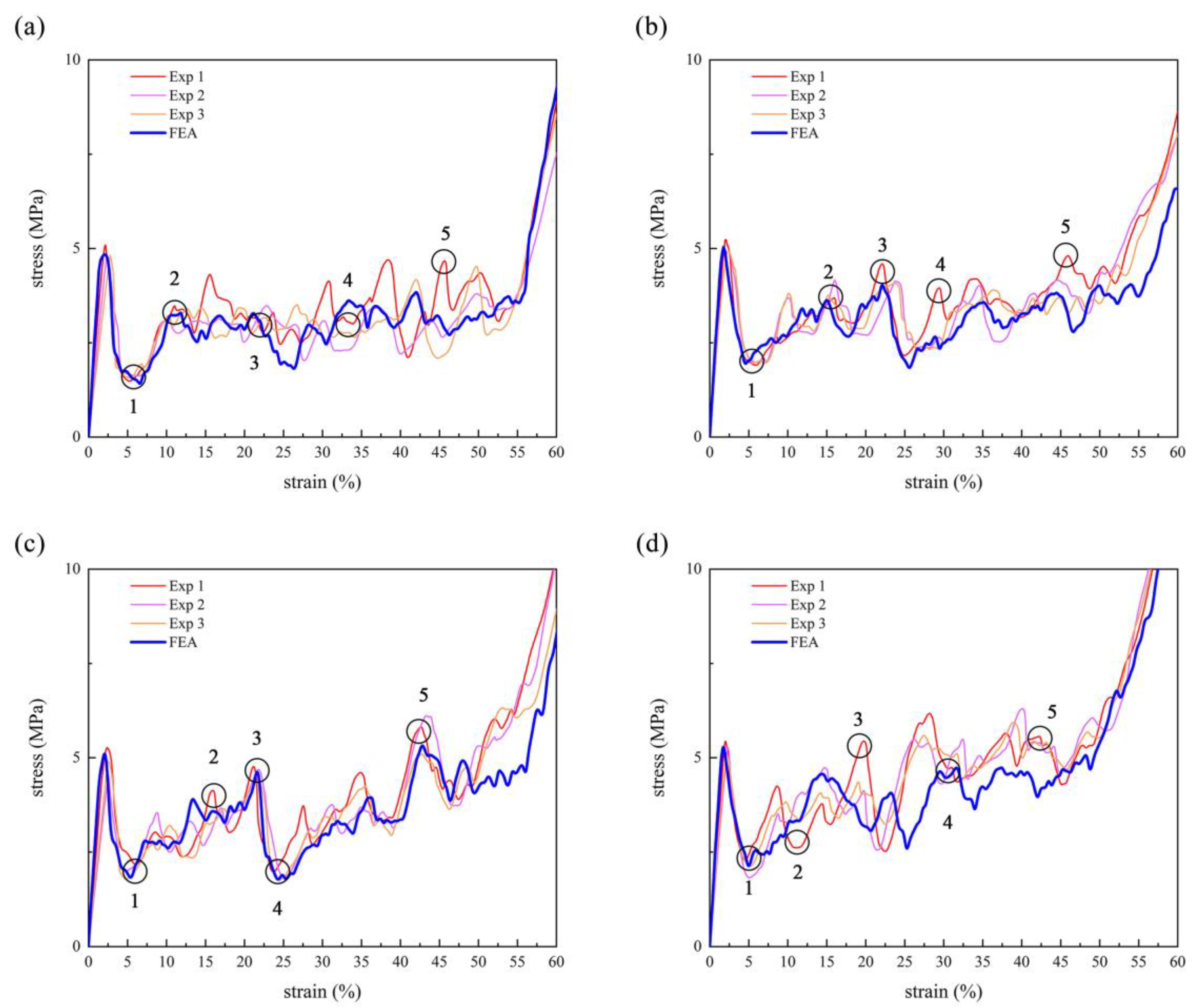
3.1. Mechanical Properties and Energy Absorption

Figure 4 illustrates quasi-static compression test results for all four structures. Each structure demonstrates a highly reproducible stress-strain response. By careful observation of all these stress-strain curves, it can be seen that an elastic-plastic collapse behavior with three distinct stages of deformation occurs, which are, linear-elastic, plateau stress and densification. Such mechanical response is analogous to that of traditional bending-dominated lattice or foams [40]. In detail, all the structures show a uniform deformation in the initial elastic region until its elastic limit. Then the cell edges yield and collapse with a sharp drop of stress. Prior to the occurrence of densification, the plateau stress stage performs a sustained oscillation in stress values due to the sudden occurrence of strut buckling and layer-to- layer collapse.
Figure 5 illustrates the difference of the mechanical properties and energy absorption capabilities for all four structures. Detailed information of experiment data is also summarized in Table 4. It can be concluded that the overall performance of the samples with meta-precipitates outperforms those without meta-precipitates. With the introduction of meta-precipitates during unit cell design, the yield strength (compressive strength) and plateau stress increase. The favorable plateau response contributes to an improvement in the energy absorption capabilities. This idea is similar to other research efforts for energy absorber applications, while the solution to the unit cell design is different [39].
In addition, the values of the major properties are in positive correlation to the number of precipitates that are introduced in the samples, at the same time the relative density of the samples increases negligibly. Therefore, the P-4 structure that consists of 4 meta-precipitates exhibit excellent energy absorption capability compared to other structures, with the total energy absorption of 2.04 × 10⁴ J/m3 (approximately 20% higher than initial P-0 structure with completely periodic arrangement), and with specific energy absorption of 39.97 J/kg. It reveals that the architected metamaterial can be significantly strengthened with the design of meta-precipitate, ensuring its capability of carrying more load especially in large deformation.
Perfect match between experimentally-measured stress-strain responses (thin curves) and simulation results (thick blue curves) could be found in Figure 4. The comparison of deformation behavior is illustrated in Figure 6. Prime property indexes obtained from experiments and simulations are summarized in Table 5, which are in good agreement with each other. The maximum difference of approximately 13% between experiments and simulations is observed for the Young’s modulus of P-0 structure. The slight deviation is probably resulted from the inconsistency of strut thickness or thermal stress caused by FDM process [41].

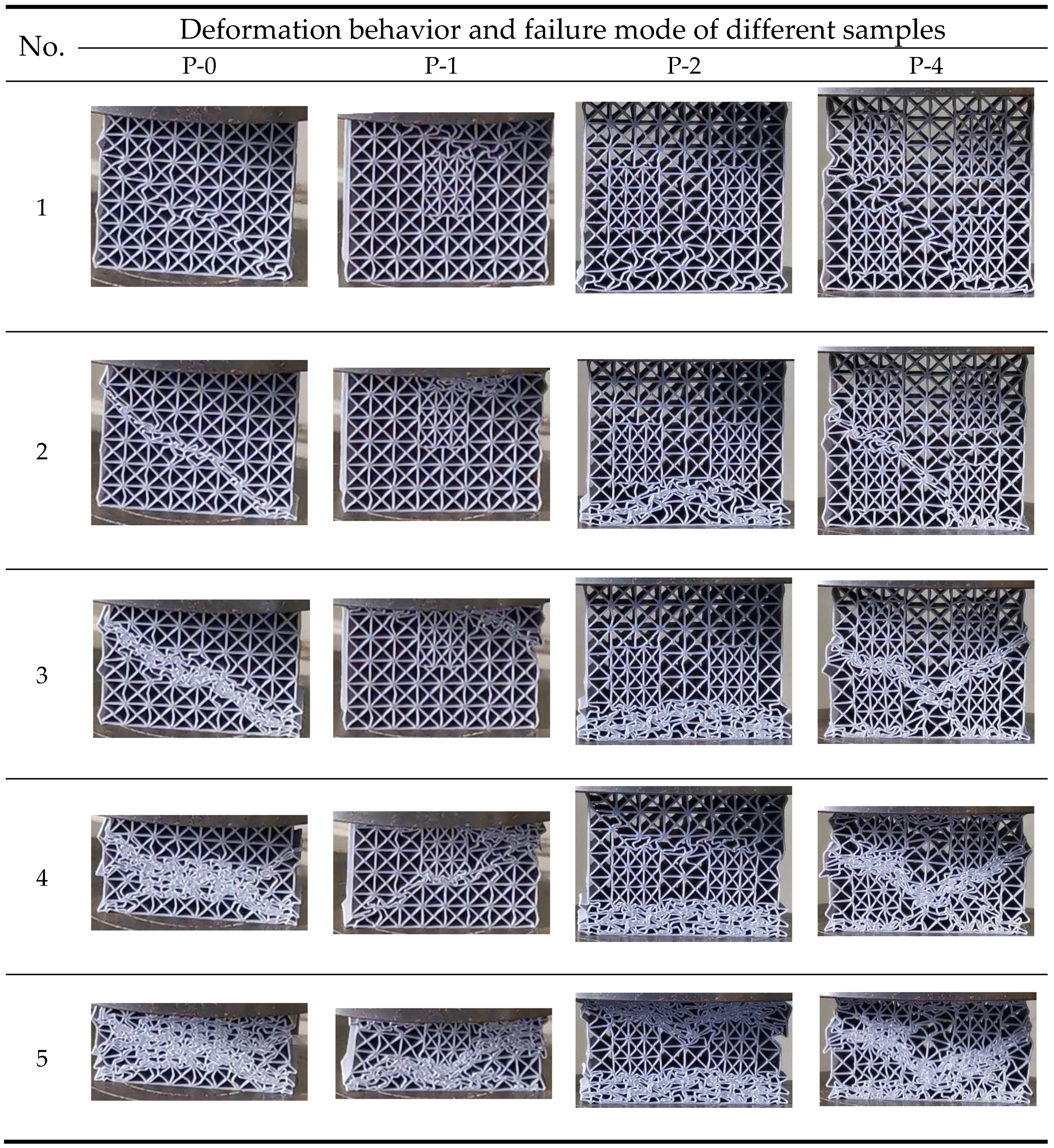
3.2. Deformation Mode

The deformation process of the four structures under quasi-static compression is presented in Figure 7 to understand the difference of deformation mode. All four structures show uniform deformation at the linear-static stage. Elastic or plastic strut buckling occurs beyond the first stress peak, which gradually results in deformation localization. Due to the introduction of meta-precipitates, there is obvious difference in the elastic limit and the initial location for deformation localization, leading to the entire difference for the deformation mode, which will be discussed respectively.
The P-0 structure exhibits a conventional diagonal crushing, which is a typical failure mode usually observed in other periodically-arranged cellular solid [42]. The localized deformation results in the formation of plastic hinge at the nodes adjacent to the diagonal. The nodes located along the diagonal is easy to concentrate more plastic deformation when the compression continues. Consequently, the strain at the nodes attains the failure strain [43], and they undergo rigid body rotations at the same time the unit cell is twisted. Once the first diagonal of twisting cells come into contact with the next row caused by this “twist mode”, additional stress is required to continue the deformation, leading to the increase of stress value. The twist behavior is then repeated, resulting in an irregular oscillation of the stress-strain curves before the densification occurs.
The deformation of P-1, P-2 and P-4 structure is different from that of the P-0 structure. For P-1 structure, the buckling of the struts initially occurs at the first two layers of the matrix, followed by a progressive crushing of the first two layers when the strain increases. Once the structure is further compressed, a diagonal crushing comes into existence. It is to some extent analogous to the deformation of P-0 structure with one distinct difference. The crushing meanders and deviates from the diagonal line when it approaches the meta-precipitate. The meta-precipitate remains almost undeformed during this process. In other word, the deformation localization changes its initial direction to bypass the meta-precipitates. This phenomenon illustrates that the meta-precipitate is stronger and can hinder the progress of deformation localization and the subsequent failure.
The P-2 structure exhibits a progressive crushing more obvious than the P-1 structure. No sign of diagonal crushing is observed before the strain comes to 0.25. The progressive crushing leads to layer-by-layer collapse. At the strain of 0.25, the diagonal crushing is also hindered or even stopped at the location adjacent to the meta-precipitate, followed by progressive crushing at the upper layers. The P-4 structure exhibits a diagonal crushing at the gaps among four meta-precipitates. The meta-precipitates remain undeformed prior to the strain of 0.31. However, it eventually rotates for further compression, leading to a stress peak and a relatively higher plateau stress in the stress-strain curve.
By comparing the deformation behavior of the four structures, it could be found that the meta-precipitates act as obstacles to the shear deformation (diagonal crushing). The deformation localization deviates from its initial direction due to the existence of meta-precipitates. It demonstrates that the meta-precipitates with different lattice parameters in our design exhibits higher strength than the matrix, thus have the ability to significantly change the deformation mode and consequently strengthen the overall architected metamaterials.

4. Discussion

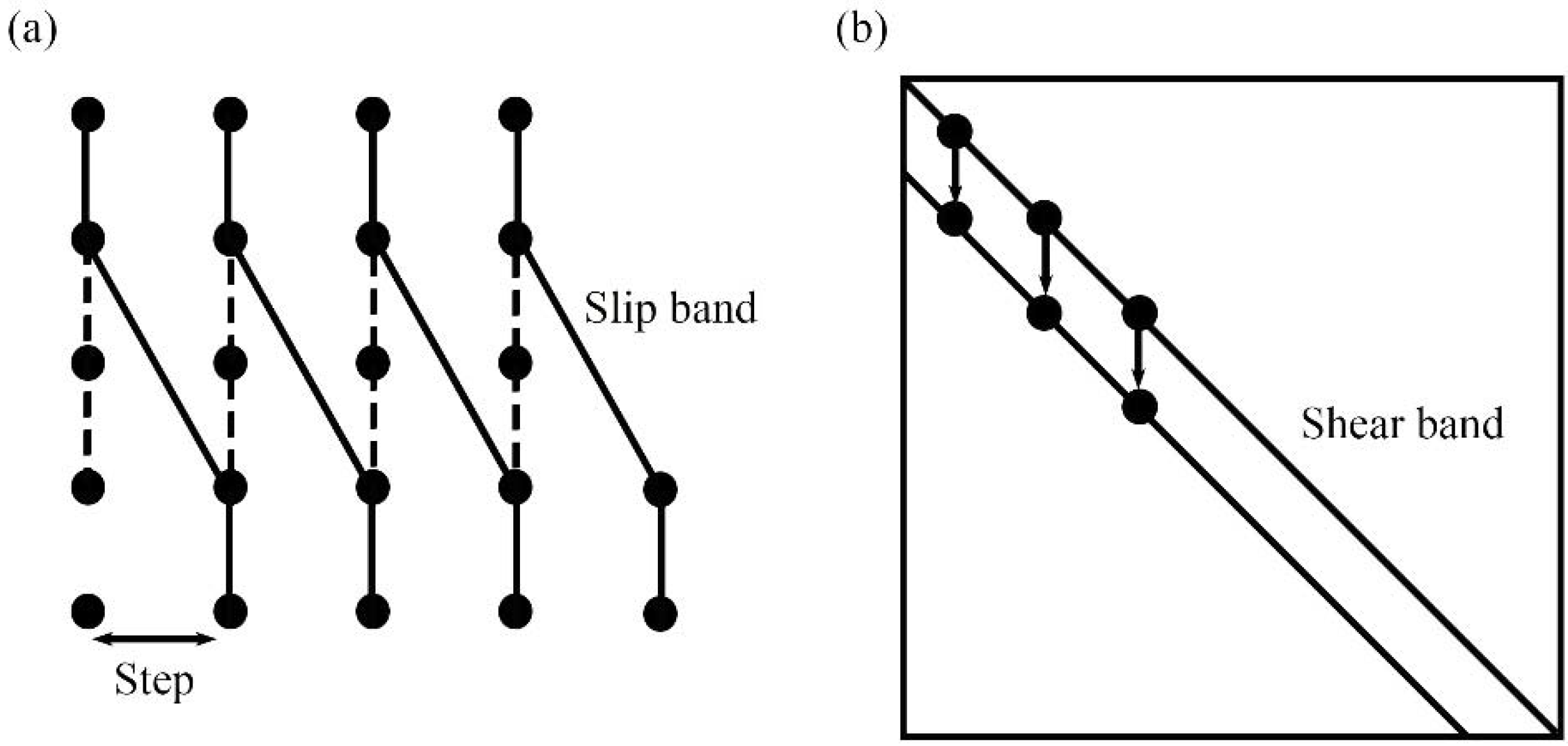
4.1. Feature of Shear Band in Architected Metamaterials

When it comes to the deformation pattern, shear band found in P-0 structure has much in common with slip band in single crystals. For P-0 structure, the localized plastic deformation at the nodes adjacent to the diagonal results in the formation of shear band and the subsequent rotation of unit cells (see Section 3.2), which leads to the highly localized deformation along the diagonal when the structure is loaded beyond the elastic limit. This sort of shear band has also been observed in samples with a variety of lattice structures such as BCC, BCC-Z and FCC-Z (similar to BCC, FCC micro-lattice but with vertical pillars), in which the deformation localization was found to be accorded with internal node movement [44]. The phenomenon is similar to the slip band along particular direction as shown in Figure 8, when single crystals are loaded beyond the yield point and undergo strain localization [27].
In addition, the plastic deformation in single crystals is generated by a dominant slip mode of dislocations, and a step with the width of a Burgers vector is formed [27]. During the process the strain becomes localized and stress for further deformation starts to decrease. Similarly, as the strain increases when the architected metamaterial is compressed, a diagonal deformation pattern occurs which can be regarded as the result of node movement along the same direction, with the width of a strut length. The movements of node also result in repeated decrease and increase of the stress.
However, shear band (in architected metamaterial) and slip band (in single crystals) differ in the way of translating macroscopic shear. In single crystals, strong interactions exist between neighboring atoms which are deemed rigid, hence atomic bonds form plastic hinges which simply allow axial compression at the atoms, resulting in continuous zones of plastic deformation. In contrast, when external stress is loaded on architected metamaterials, the highly concentrated strains around the nodes could generate new plastic hinges near the center of the struts, which lead to the rigid body rotations of strut intersections, corresponding to the localized deformation and collapse behaviors of materials.
The analysis demonstrates that the P-0 structure with completely periodic arrangement of microstructures is roughly similar to single crystals in its deformation mode, however it is still distinct because of the attempt to mimic crystallographic microstructures at a macroscale level.

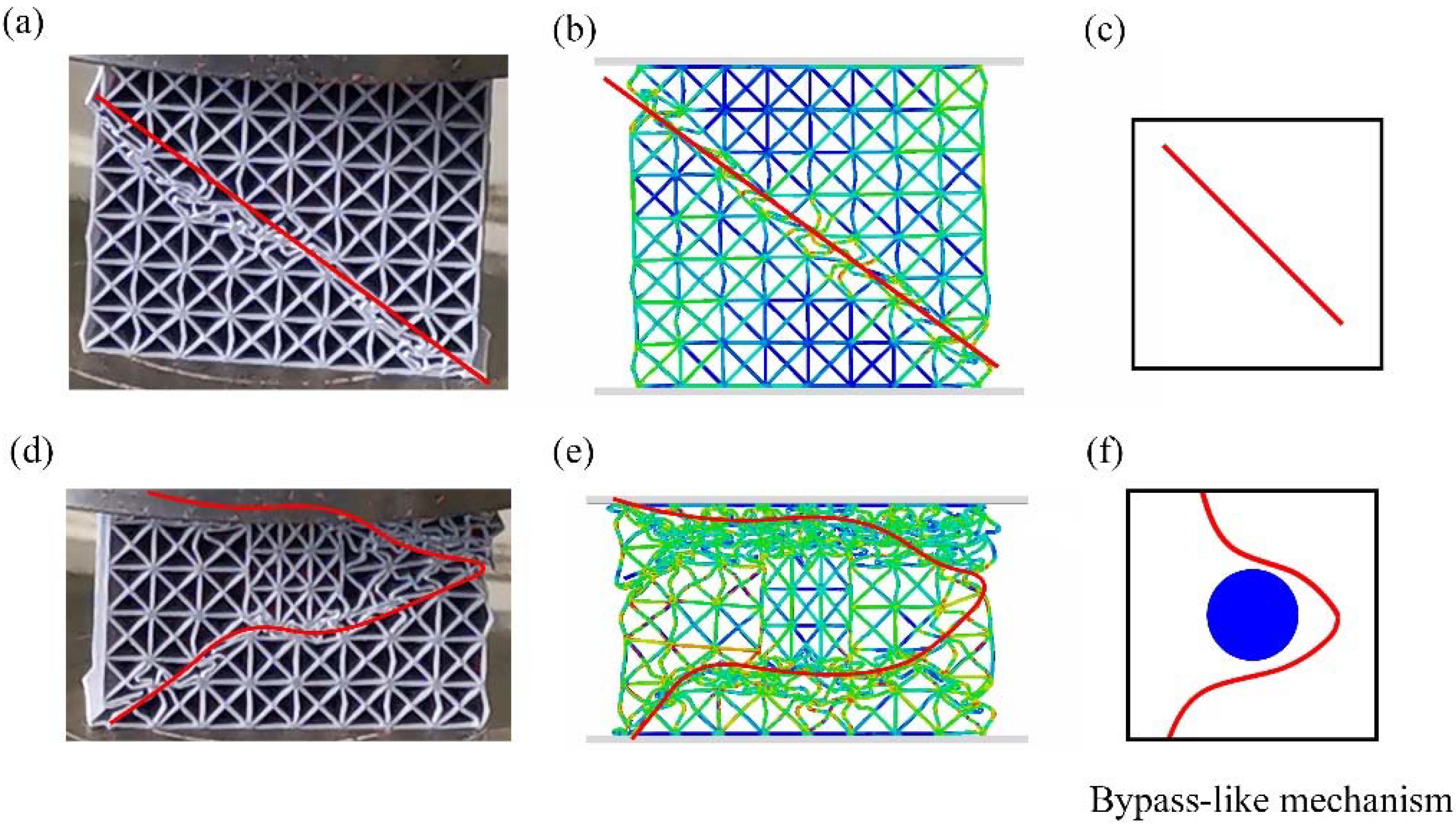
4.2. Orowan Bypass-Like Strengthening Mechanism in Architected Metamaterials

A significant strengthening effect has been found in architected metamaterials by the introduction of meta-precipitates (see Section 3.1). Here we discuss the reason for the strengthening and compare the strengthening mechanism of architected metamaterials (at a macroscale level) with the Orowan bypass strengthening mechanism (at a microscale level).

4.2.1. Hindering Effect of Meta-Precipitates

The strengthening mechanism in architected metamaterials is largely dependent on the hindering effect of meta-precipitates on the shear band formation. In the experimental and numerical results, the initial deformation localization deviates from its diagonal direction to a meander path. When such path approaches the interface between the matrix and meta-precipitates, the shear band bows or even stops to bypass the meta-precipitates, which is commonly observed in experiments and FE predictions in P-1, P-2 and P-4 structure, as is shown in Figure 9. As the consequence, the overall performance of the architected metamaterials is substantially enhanced due to the control of shear band propagation. This phenomenon illustrates the hindering effect of meta-precipitates.
The reinforcement of the structure is similar to the Orowan bypass strengthening mechanism [45]. In Orowan effect, precipitations serve as the obstacles of dislocation movement in precipitation-hardened alloys [30], and the slip plane bows under the interaction between dislocation and precipitates [46]. In precipitate-type architected metamaterials, the embedded meta-precipitates also hinder the shear band propagation during compression, and the meander fracture route substantially improves the strength. This similarity between precipitation-hardened alloys and precipitate-type architected metamaterials demonstrates the applicability of combining metallurgical hardening principles with structural design.

4.2.2. Influence of Volume Fraction of Meta-Precipitates

There are several factors that affect the strengthening of precipitation, such as volume fraction of the precipitates, strain rate, temperature, and the coherency between precipitates and matrix [47]. Here we discuss the influence of volume fraction of meta-precipitates on the strength of architected metamaterials, to further illustrates that the strengthening mechanism similar to precipitation hardening is applicable to architected metamaterials.
In precipitation hardening, the relationship between the increase of yield stress τ y and the particle spacing of precipitates L can be expressed by the Orowan Equation (3) [48]:
τ y = G b / L
where G is the shear modulus of the matrix and b is the Burgers vector.
The relationship illustrates that a higher volume fraction of the precipitates leads to a reduced spacing and a significant increase in yield stress. In architected metamaterials embedded with meta-precipitates, the yield stress (compressive strength) is also in a positive correlation to the volume fraction of the meta-precipitates. The increase of volume fraction also leads to a higher plateau stress and an improved energy absorption ability.

4.2.3. Difference in Deformation Evolution

While atomic bonds are mimicked by the struts in architected metamaterials, several differences are noteworthy.
First, compared with the continuous deformation zones of crystalline materials in which only axial compression or collapse may occur, the shear bands contain strut intersections which render rigid body rotation as mentioned above. Such twist inevitably depletes extra energy and may contribute to the hindering mechanism in architected meta-materials.
Second, in crystalline materials, the slip plane bows out under the influence of the applied stress into an arc when the dislocation encounters the precipitates [46]. Such arc-shaped dislocation may further expand and interact with other obstacles before it could no longer endure the force acting upon it and break free, which drains additional expansion energy and impedes the dilation of slip band. On the contrary, the radian of the shear band in architected materials after plastic deformation is restrained, since the printed struts could only bend to a limited extent due to its shear strength.
Third, unlike the slip band of crystalline materials in which Orowan loops are formed to let through the dislocation, the shear band of architected metamaterials is incapable of bypassing the embedded lattices entirely, due to the limitation of edges and boundaries. Instead, the shear front ceases to proceed after it reaches the buckling limit. When the structure is further compressed, a new shear plane is generated, which is derived from the side edge of the structure. The new shear plane is in a mirror symmetry relationship with the previous plane to transfer further deformation. The evolution of the new plane is still along the diagonal but hindered by the meta-precipitates.
The main cause of the difference is possibly related to the connectivity of the nodes and struts in our work which is unable to completely simulate the atomic bonds in crystallographic microstructures, the boundaries of architected metamaterial we design and the limited meta-precipitates that are introduced.

5. Conclusions

In the present work, four precipitate-type architected metamaterials are designed and investigated. We mimic the crystallographic configurations of precipitation-hardened materials by embedding lattice domains (meta-precipitates) into the periodic unit cells (matrix). The structures exhibit in-plane performance improvement as the introduction of meta-precipitates. The P-4 structure with 4 meta-precipitates shows total energy absorption of 2.04 × 10⁴ J/m3, 20% higher than the P-0 structure without any precipitates.
The precipitate-type architected metamaterials demonstrate a particular evolution of deformation. The meta-precipitates act as obstacles to compression, changing the deformation mode from original diagonal crushing to a meander failure route bypassing the precipitates, which is the main cause of the enhanced mechanical properties. The hindering effect of meta-precipitates and the positive relationship between yield stress and the volume fraction of the meta-precipitates are similar to Orowan bypass strengthening mechanism in crystalline materials. The difference is mainly caused by the uncomplete simulation of atomic bonds through struts and nodes in architected metamaterials.
The particular way of deformation found in these structures helps us understand how unit cells collapse when the meta-precipitates are introduced. The functionality and performance of the architected metamaterials that we can tailor can be used in various applications where the location of collapse should be controlled. In addition, by establishing the similarities and discrepancies of metallurgical hardening principles and that found in architected metamaterials, we open up the possibilities of studying complex metallurgical phenomenon at a macroscale level.

Author Contributions

Conceptualization, Z.L., P.Y. and B.Y.; methodology, Z.L. and P.Y.; software, Z.L.; validation, Z.L., P.Y. and B.Y.; formal analysis, Z.L.; data curation, Z.L.; writing—original draft preparation, Z.L. and W.Y.; writing—review and editing, Z.L., W.Y. and P.Y.; visualization, Z.L.; supervision, B.Y.; funding acquisition, B.Y. All authors have read and agreed to the published version of the manuscript.

Funding

This research received no external funding.

Conflicts of Interest

The authors declare no conflict of interest.

References

  1. Xu, J.; Gao, L.; Xiao, M.; Gao, J.; Li, H. Isogeometric topology optimization for rational design of ultra-lightweight architected materials. Int. J. Mech. Sci. 2020, 166, 105103. [Google Scholar] [CrossRef]
  2. Schaedler, T.A.; Carter, W.B. Architected Cellular Materials. Annu. Rev. Mater. Res. 2016, 46, 187–210. [Google Scholar] [CrossRef]
  3. Schaedler, T.; Jacobsen, A.; Torrents, A.; Sorensen, A.; Lian, J.; Greer, J.; Valdevit, L.; Carter, W. Ultralight Metallic Microlattices. Science 2011, 334, 962–965. [Google Scholar] [CrossRef] [PubMed]
  4. Yi, F.; Zhu, Z.; Zu, F.; Hu, S.; Yi, P. Strain rate effects on the compressive property and the energy-absorbing capacity of aluminum alloy foams. Mater. Charact. 2001, 47, 417–422. [Google Scholar] [CrossRef]
  5. Andreassen, E.; Lazarov, B.S.; Sigmund, O. Design of manufacturable 3D extremal elastic microstructure. Mech. Mater. 2014, 69, 1–10. [Google Scholar] [CrossRef] [Green Version]
  6. Chen, Y.; Jia, Z.; Wang, L. Hierarchical honeycomb lattice metamaterials with improved thermal resistance and mechanical properties. Compos. Struct. 2016, 152, 395–402. [Google Scholar] [CrossRef] [Green Version]
  7. Li, X.; Wang, Z.; Zhu, F.; Wu, G.; Zhao, L. Response of aluminium corrugated sandwich panels under air blast loadings: Experiment and numerical simulation. Int. J. Impact Eng. 2014, 65, 79–88. [Google Scholar] [CrossRef]
  8. Rogers, J.A.; Someya, T.; Huang, Y. Materials and Mechanics for Stretchable Electronics. Science 2010, 327, 1603. [Google Scholar] [CrossRef] [Green Version]
  9. Aboulkhair, N.T.; Simonelli, M.; Parry, L.; Ashcroft, I.; Tuck, C.; Hague, R. 3D printing of Aluminium alloys: Additive Manufacturing of Aluminium alloys using selective laser melting. Prog. Mater. Sci. 2019, 106, 100578. [Google Scholar] [CrossRef]
  10. Niino, T. Additive Manufacturing Technologies—From Rapid Prototyping to Rapid Manufacturing. J. Jpn. Soc. Precis. Eng. 2010, 76, 1340–1344. [Google Scholar] [CrossRef] [Green Version]
  11. Xue, R.; Cui, X.; Zhang, P.; Liu, K.; Li, Y.; Wu, W.; Liao, H. Mechanical design and energy absorption performances of novel dual scale hybrid plate-lattice mechanical metamaterials. Extreme Mech. Lett. 2020, 40, 100918. [Google Scholar] [CrossRef]
  12. Wagner, M.A.; Lumpe, T.S.; Chen, T.; Shea, K. Programmable, active lattice structures: Unifying stretch-dominated and bending-dominated topologies. Extreme Mech. Lett. 2019, 29, 100461. [Google Scholar] [CrossRef]
  13. Mines, R.A.W.; Tsopanos, S.; Shen, Y.; Hasan, R.; McKown, S.T. Drop weight impact behaviour of sandwich panels with metallic micro lattice cores. Int. J. Impact Eng. 2013, 60, 120–132. [Google Scholar] [CrossRef] [Green Version]
  14. Ushijima, K.; Cantwell, W.; Mines, R.; Tsopanos, S.; Smith, M. An investigation into the compressive properties of stainless steel micro-lattice structures. J. Sandw. Struct. Mater. 2010, 12. [Google Scholar] [CrossRef]
  15. Tancogne-Dejean, T.; Mohr, D. Elastically-isotropic truss lattice materials of reduced plastic anisotropy. Int. J. Solids Struct. 2018, 138, 24–39. [Google Scholar] [CrossRef]
  16. Jin, N.; Wang, F.; Wang, Y.; Zhang, B.; Cheng, H.; Zhang, H. Effect of structural parameters on mechanical properties of Pyramidal Kagome lattice material under impact loading. Int. J. Impact Eng. 2019, 132, 103313. [Google Scholar] [CrossRef]
  17. Trifale, N.; Nauman, E.; Yazawa, K. Systematic Generation, Analysis and Characterization of 3D Micro-architected Meta- materials. ACS Appl. Mater. Interfaces 2016, 8. [Google Scholar] [CrossRef]
  18. Wendy Gu, X.; Greer, J.R. Ultra-strong architected Cu meso-lattices. Extreme Mech. Lett. 2015, 2, 7–14. [Google Scholar] [CrossRef]
  19. Wang, B.; Wu, L.; Ma, L.; Sun, Y.; Du, S. Mechanical behavior of the sandwich structures with carbon fiber-reinforced pyramidal lattice truss core. Mater. Des. (1980–2015) 2010, 31, 2659–2663. [Google Scholar] [CrossRef]
  20. Wang, P.; Fan, H.; Xu, B.; Mei, J.; Wu, K.; Wang, H.; He, R.; Fang, D. Collapse criteria for high temperature ceramic lattice truss materials. Appl. Thermal Eng. 2015, 89, 505–513. [Google Scholar] [CrossRef]
  21. Pham, M.-S.; Holdsworth, S. Evolution of Relationships Between Dislocation Microstructures and Internal Stresses of AISI 316L During Cyclic Loading at 293 K and 573 K (20 °C and 300 °C). Metall. Mater. Trans. A 2013, 45. [Google Scholar] [CrossRef] [Green Version]
  22. Maskery, I.; Aboulkhair, N.T.; Aremu, A.O.; Tuck, C.J.; Ashcroft, I.A. Compressive failure modes and energy absorption in additively manufactured double gyroid lattices. Addit. Manuf. 2017, 16, 24–29. [Google Scholar] [CrossRef]
  23. Qiu, C.; Yue, S.; Adkins, N.J.E.; Ward, M.; Hassanin, H.; Lee, P.D.; Withers, P.J.; Attallah, M.M. Influence of processing conditions on strut structure and compressive properties of cellular lattice structures fabricated by selective laser melting. Mater. Sci. Eng. A 2015, 628, 188–197. [Google Scholar] [CrossRef]
  24. Maskery, I.; Aboulkhair, N.T.; Aremu, A.O.; Tuck, C.J.; Ashcroft, I.A.; Wildman, R.D.; Hague, R.J.M. A mechanical property evaluation of graded density Al-Si10-Mg lattice structures manufactured by selective laser melting. Mater. Sci. Eng. A 2016, 670, 264–274. [Google Scholar] [CrossRef] [Green Version]
  25. Gu, H.; Pavier, M.; Shterenlikht, A. Experimental study of modulus, strength and toughness of 2D triangular lattices. Int. J. Solids Struct. 2018, 152, 207–216. [Google Scholar] [CrossRef]
  26. Qi, D.; Yu, H.; Liu, M.; Huang, H.; Xu, S.; Xia, Y.; Qian, G.; Wu, W. Mechanical behaviors of SLM additive manufactured octet-truss and truncated-octahedron lattice structures with uniform and taper beams. Int. J. Mech. Sci. 2019, 163, 105091. [Google Scholar] [CrossRef] [Green Version]
  27. Dimiduk, D.M.; Uchic, M.D.; Parthasarathy, T.A. Size-affected single-slip behavior of pure nickel microcrystals. Acta Mater. 2005, 53, 4065–4077. [Google Scholar] [CrossRef]
  28. Chalmers, B. Dislocations and Plastic Flow in Crystals. Dislocations in CrystalsA.H. Cottrell. Acta Metall. 1954, 2, 170. [Google Scholar] [CrossRef]
  29. Pham, M.S.; Holdsworth, S.R.; Janssens, K.G.F.; Mazza, E. Cyclic deformation response of AISI 316L at room temperature: Mechanical behaviour, microstructural evolution, physically-based evolutionary constitutive modelling. Int. J. Plast. 2013, 47, 143–164. [Google Scholar] [CrossRef]
  30. Argon, A. Strengthening Mechanisms in Crystal Plasticity; University Press Scholarship Online: Oxford, UK, 2008. [Google Scholar] [CrossRef] [Green Version]
  31. Pham, M.-S.; Liu, C.; Todd, I.; Lertthanasarn, J. Damage-tolerant architected materials inspired by crystal microstructure. Nature 2019, 565, 305–311. [Google Scholar] [CrossRef] [PubMed]
  32. Lakes, R.S. Size effects and micromechanics of a porous solid. J. Mater. Sci. 1983, 18, 2572–2580. [Google Scholar] [CrossRef]
  33. Hirsch, P.B.; Humphreys, F.J. The deformation of single crystals of copper and copper-zinc alloys containing alumina particles—I. Macroscopic properties and workhardening theory. Proc. R. Soc. Lond. A Math. Phys. Sci. 1970, 318, 45–72. [Google Scholar] [CrossRef]
  34. Gibson, L.; Ashby, M. Cellular Solids: Structure and Properties; Cambridge University Press: Cambridge, UK, 1997. [Google Scholar]
  35. Penumakala, P.K.; Santo, J.; Thomas, A. A critical review on the fused deposition modeling of thermoplastic polymer composites. Compos. Part B Eng. 2020, 201, 108336. [Google Scholar] [CrossRef]
  36. Corapi, D.; Morettini, G.; Pascoletti, G.; Zitelli, C. Characterization of a Polylactic acid (PLA) produced by Fused Deposition Modeling (FDM) technology. Procedia Struct. Integr. 2019, 24, 289–295. [Google Scholar] [CrossRef]
  37. Garzon-Hernandez, S.; Garcia Gonzalez, D.; Jérusalem, A.; Arias, A. Design of FDM 3D printed polymers: An experimental-modelling methodology for the prediction of mechanical properties. Mater. Des. 2020. [Google Scholar] [CrossRef]
  38. Dawoud, M.; Taha, I.; Ebeid, S.J. Mechanical behaviour of ABS: An experimental study using FDM and injection moulding techniques. J. Manuf. Process. 2016, 21, 39–45. [Google Scholar] [CrossRef]
  39. Schaedler, T.A.; Ro, C.J.; Sorensen, A.E.; Eckel, Z.; Yang, S.S.; Carter, W.B.; Jacobsen, A.J. Designing Metallic Microlattices for Energy Absorber Applications. Adv. Eng. Mater. 2014, 16, 276–283. [Google Scholar] [CrossRef]
  40. Ashby, M.F. The properties of foams and lattices. Philos. Trans. R. Soc. A Math. Phys. Eng. Sci. 2006, 364, 15–30. [Google Scholar] [CrossRef]
  41. Mohamed, O.A.; Masood, S.H.; Bhowmik, J.L. Optimization of fused deposition modeling process parameters for dimensional accuracy using I-optimality criterion. Measurement 2016, 81, 174–196. [Google Scholar] [CrossRef]
  42. Sha, Y.; Jiani, L.; Haoyu, C.; Ritchie, R.O.; Jun, X. Design and strengthening mechanisms in hierarchical architected materials processed using additive manufacturing. Int. J. Mech. Sci. 2018, 149, 150–163. [Google Scholar] [CrossRef]
  43. Tankasala, H.C.; Fleck, N.A. The crack growth resistance of an elastoplastic lattice. Int. J. Solids Struct. 2020, 188, 233–243. [Google Scholar] [CrossRef]
  44. Wang, G.; Chen, X.; Qiu, C. On the macro- and micro-deformation mechanisms of selectively laser melted damage tolerant metallic lattice structures. J. Alloys Compd. 2020, 852, 156985. [Google Scholar] [CrossRef]
  45. Orowan, E. Classification and Nomenclature of Internal Stresses; Symposium on Internal Stresses in Metals and Alloys Institute of Metals; Royal Institution of Great Britain: London, UK, 1947. [Google Scholar]
  46. Lloyd, D.J. Precipitation Hardening. In Strength of Metals and Alloys (ICSMA 7); McQueen, H.J., Bailon, J.P., Dickson, J.I., Jonas, J.J., Akben, M.G., Eds.; Elsevier: Pergamon, Turkey, 1986; pp. 1745–1778. [Google Scholar] [CrossRef]
  47. Humphreys, F.J.; Hirsch, P.B. The deformation of single crystals of copper and copper-zinc alloys containing alumina particles—II. Microstructure and dislocation-particle interactions. Proc. R. Soc. Lond. A Math. Phys. Sci. 1970, 318, 73–92. [Google Scholar] [CrossRef]
  48. Zhou, T.; Ding, H.; Ma, X.; Feng, W.; Zhao, H.; Li, A.; Meng, Y.; Zhang, H. Effect of precipitates on high-temperature tensile strength of a high W-content cast Ni-based superalloy. J. Alloys Compd. 2019, 797, 486–496. [Google Scholar] [CrossRef]
Figure 1. Unit cell designs: (a) unit cell for matrix (b) unit cell for lattice domains (meta-precipitates) (c) natural view for P-0 structure (embedded with 1 meta-precipitate) (dg) vertical view for P-0, P-1, P-2 and P-4 structure, respectively.
Applsci 10 07525 g001
Figure 2. Boundary conditions used for FE simulations.
Applsci 10 07525 g002
Figure 3. Stress-strain curves of the hexagonal honeycomb under compression.
Applsci 10 07525 g003
Figure 4. Constitutive stress-strain responses for (a) P-0 type, (b) P-1 type (c) P-2 type (d) P-4 type (Each curve contains 3 experimental data and 1 numerical result. The numbers are corresponding to the deformation behavior depicted in Figure 7).
Applsci 10 07525 g004
Figure 5. The comparison of mechanical responses for four structures: (a) stress-strain curves (b) yield strength and plateau stress (c) specific energy absorption and energy absorption efficiency.
Applsci 10 07525 g005
Figure 6. A comparison of experimental and numerical results of the four structures under different strain.
Applsci 10 07525 g006
Figure 7. Deformation behavior and failure mode of four structures under compression.
Applsci 10 07525 g007
Figure 8. Diagram of: (a) slip band in single crystals, (b) shear band in architected metamaterials.
Applsci 10 07525 g008
Figure 9. Experimental and numerical deformation and an abstract diagram of: (ac) P-0 structure, (df) P-1 structure.
Applsci 10 07525 g009
Table 1. Strut thickness deviation for samples.
SampleStrut Thickness (mm)Average Thickness (mm)Theoretical Thickness (mm)Error
123
P-00.4820.4670.5110.4870.5002.6%
P-10.4580.4930.4870.4794.2%
P-20.4970.4760.4650.4794.2%
P-40.4830.4920.4800.4853.0%
Note: Error = |Theory − Average|/Theory × 100%.
Table 2. Material properties of PLA+ polymer.
MaterialYoung’s Modulus, EsPoisson’s Ratio Density ,   ρ s Yield   Stress ,   σ y s
PLA+2.0 GPa0.351.26 g/cm339 MPa
Table 3. Numerical, experimental and theoretical calculation of plateau stress.
FE Result (MPa)Experiment Result (MPa)Theoretical Result (MPa)Error
4.564.333.925.04%
Error = (FE result − Experiment result)/FE result × 100%.
Table 4. Major mechanical properties of the different specimens under quasi-static compression test.
SampleYoung’s Modulus (GPa)Yield Strength (MPa)Energy Absorption (×104 J/m3)Energy Absorption Efficiency (%)
P-012.505.071.8264.02
22.404.761.6260.61
32.274.841.6560.98
P-113.184.921.8565.79
23.195.041.8067.41
33.044.911.8267.62
P-213.275.242.0766.81
23.164.911.8473.76
33.124.871.8968.63
P-413.165.422.0978.30
23.295.242.0175.87
33.385.152.0282.81
Table 5. Comparison of experimental (Exp) and numerical (FEA) results under quasi-static compression test.
SampleYoung’s Modulus (GPa)Yield Strength (MPa)Energy Absorption (×104 J/m3)Energy Absorption Efficiency (%)
P-0Exp2.394.891.7061.87
FEA2.714.841.6460.43
Error13.39%9.20%3.53%2.33%
P-1Exp3.144.961.8266.67
FEA3.384.961.8364.04
Error7.64%0.00%0.01%3.94%
P-2Exp3.185.011.9369.73
FEA3.365.071.8668.51
Error5.66%1.20%3.63%1.75%
P-4Exp3.275.272.0478.99
FEA3.485.251.9473.90
Error6.42%0.00%4.90%6.44%
Note: Error = |Exp − FEA|/Exp × 100%.
Publisher’s Note: MDPI stays neutral with regard to jurisdictional claims in published maps and institutional affiliations.

