A Novel Hazard Analysis and Risk Assessment Approach for Road Vehicle Functional Safety through Integrating STPA with FMEA
Abstract
Featured Application
Abstract
1. Introduction
2. Background
2.1. ISO26262 for Road Vehicle Functional Safety
- Item definition: the object of this process is to describe the functionality, interfaces between other items, the driver and the environment of an item. This step is the input of the HARA process.
- The HARA process is made up of three steps:
- (1)
- Determine the hazardous events according to identified vehicle-level hazards, corresponding operational situations and operating modes.
- (2)
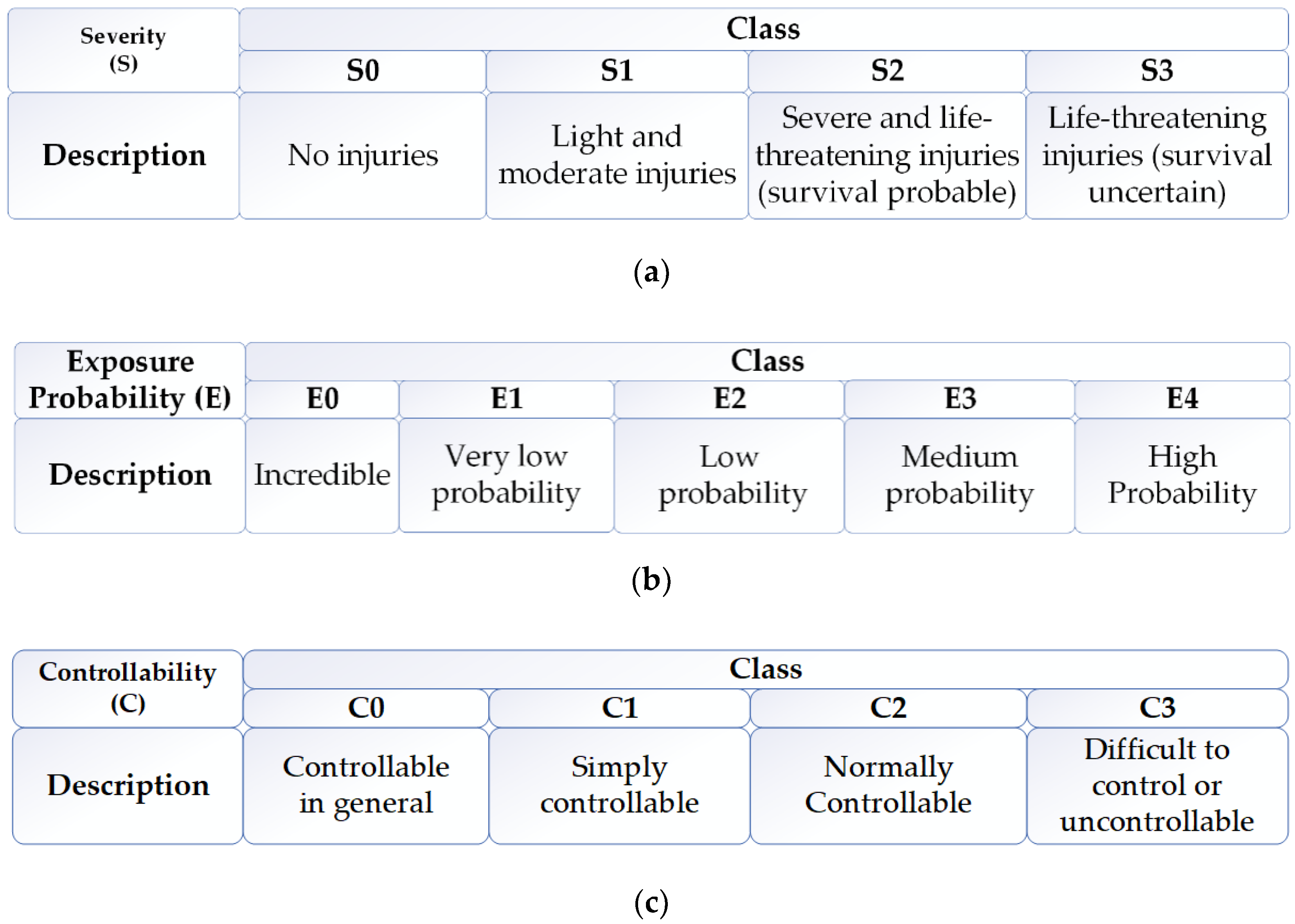
- For each identified vehicle-level hazard, the risk assessment framework of ISO26262 is applied:
- The probability of exposure (E) to the operational situation is assessed.
- Identify potential scenarios which can cause a crash. The severity (S) of the harm to the persons involved is assessed if the crash happened.
- The controllability (C) of the vehicle and the operational situations is assessed.
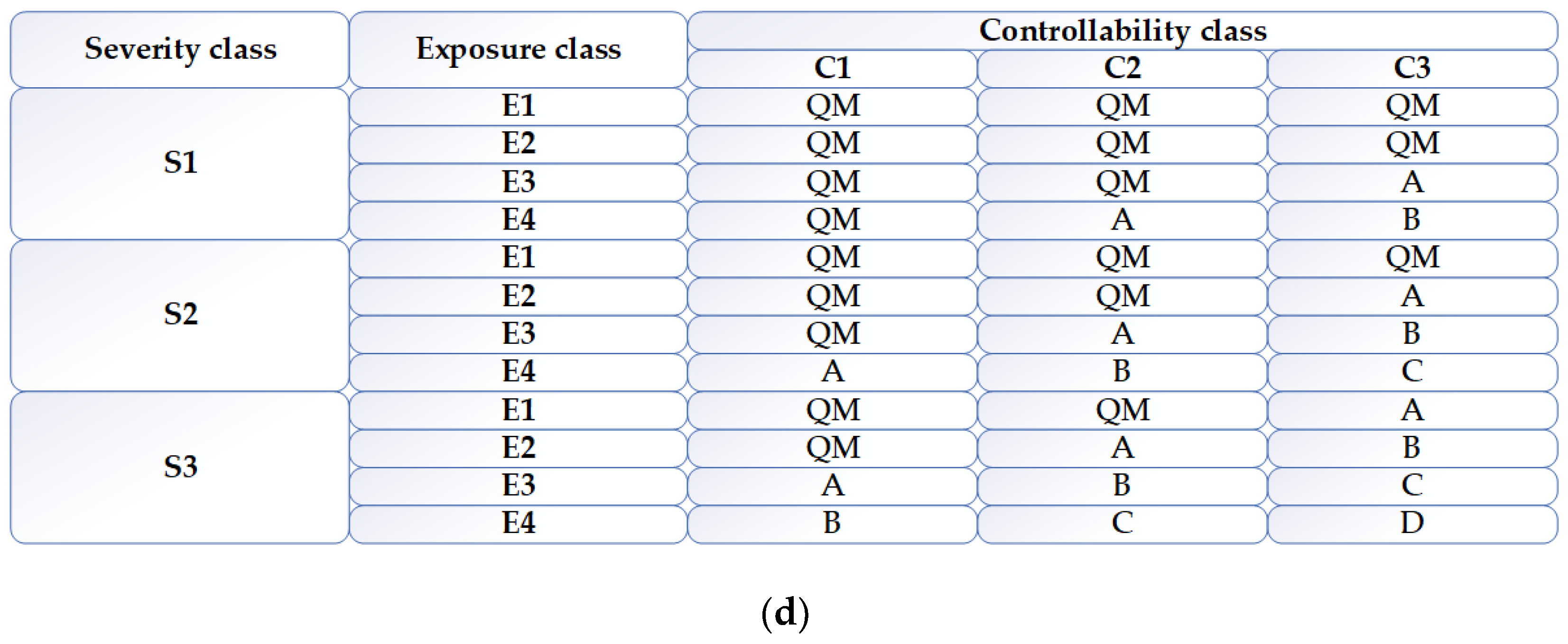
- Determine the automotive safety integrity level (ASIL) based on E, S and C according to ISO 26262 as shown in Figure 1.
- (3)
- The worst-case ASIL is assigned to the hazardous event.
- SGs shall be determined for each identified hazardous event with its ASIL.
- Functional safety concept: the most important objective of this step is the derivation of FSRs from the SGs, considering the system architectural design.
2.2. System Theoretic Process Analysis
- The first is to establish the engineering fundamentals, including the determination of accidents, identification of system-level hazards leading to accidents, and the contribution of the system safety control structure.
- Identify potential unsafe control actions (UCAs) leading to hazards using the safety control structure constructed in the previous step.
- Identified causal factors leading to UCAs or a violation of SCs by examining each part in the control structure.
2.3. Failure Mode and Effect Analysis
2.4. Related Work
3. Hazard Analysis Foundations and Key Terms of STPA and ISO26262
3.1. Hazard Analysis Foundations of the HARA Process in ISO26262 and STPA
3.2. Key Terms of ISO26262 Concept Phase and STPA
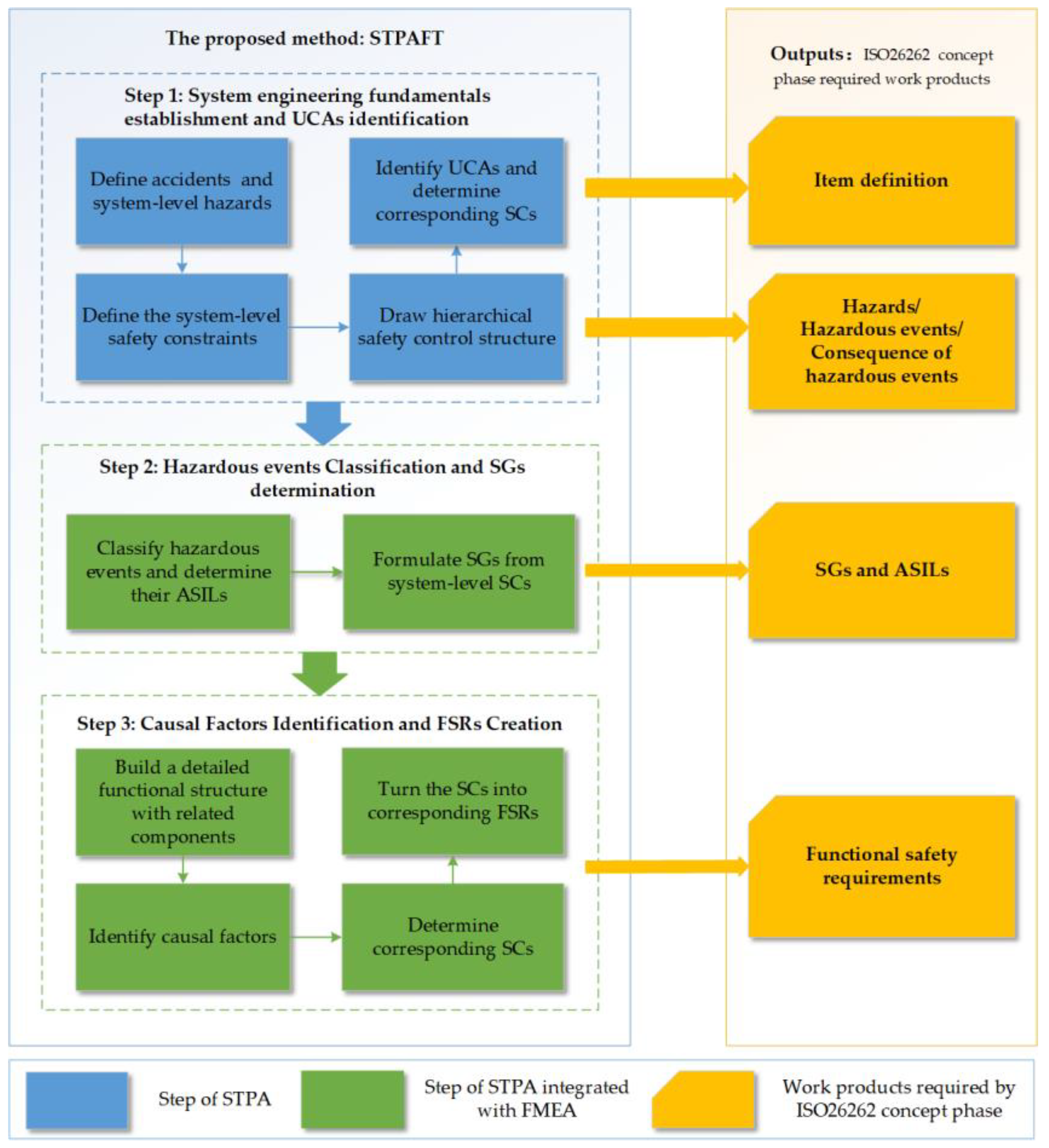
4. The Proposed Method
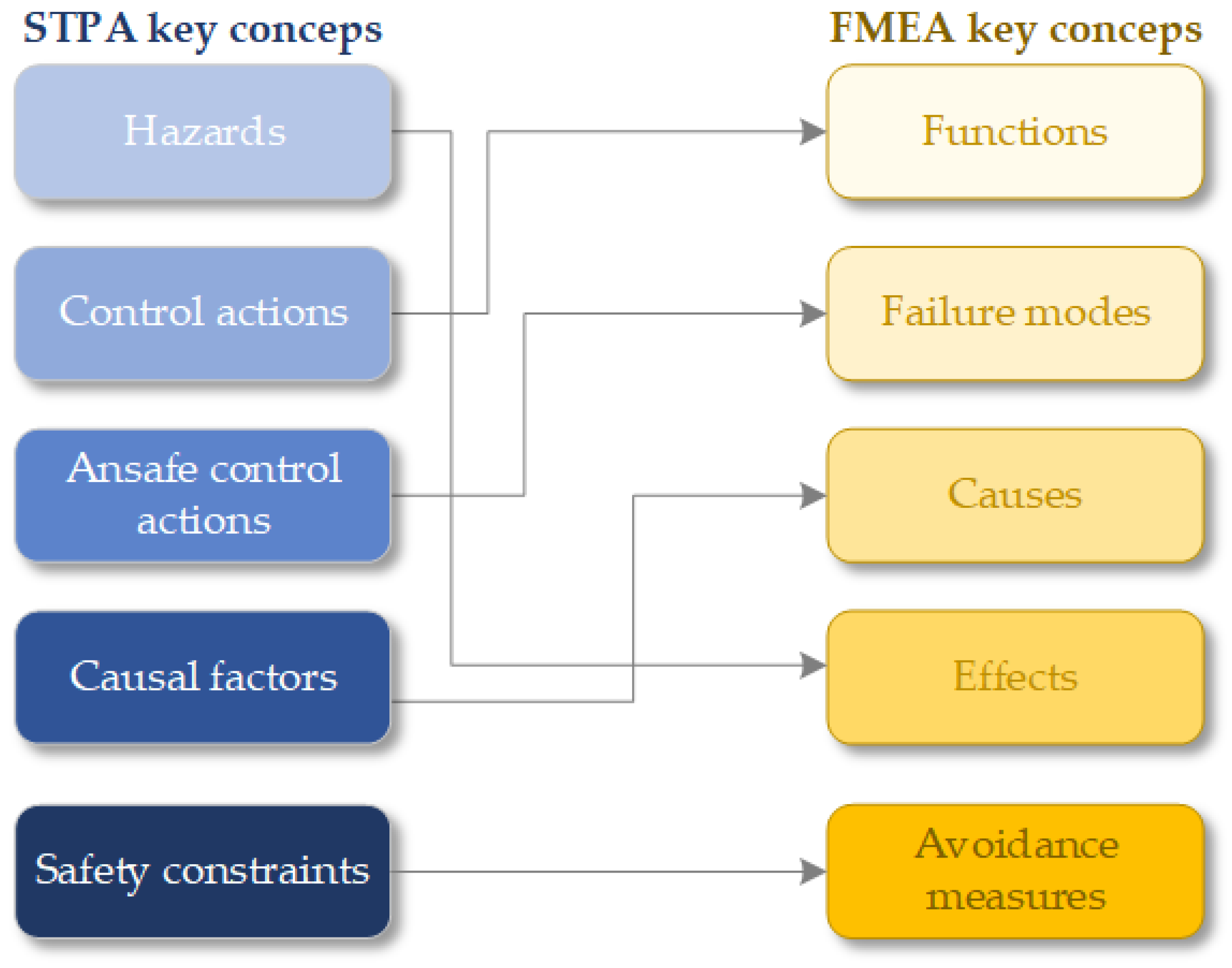
4.1. Integrating STPA into FMEA
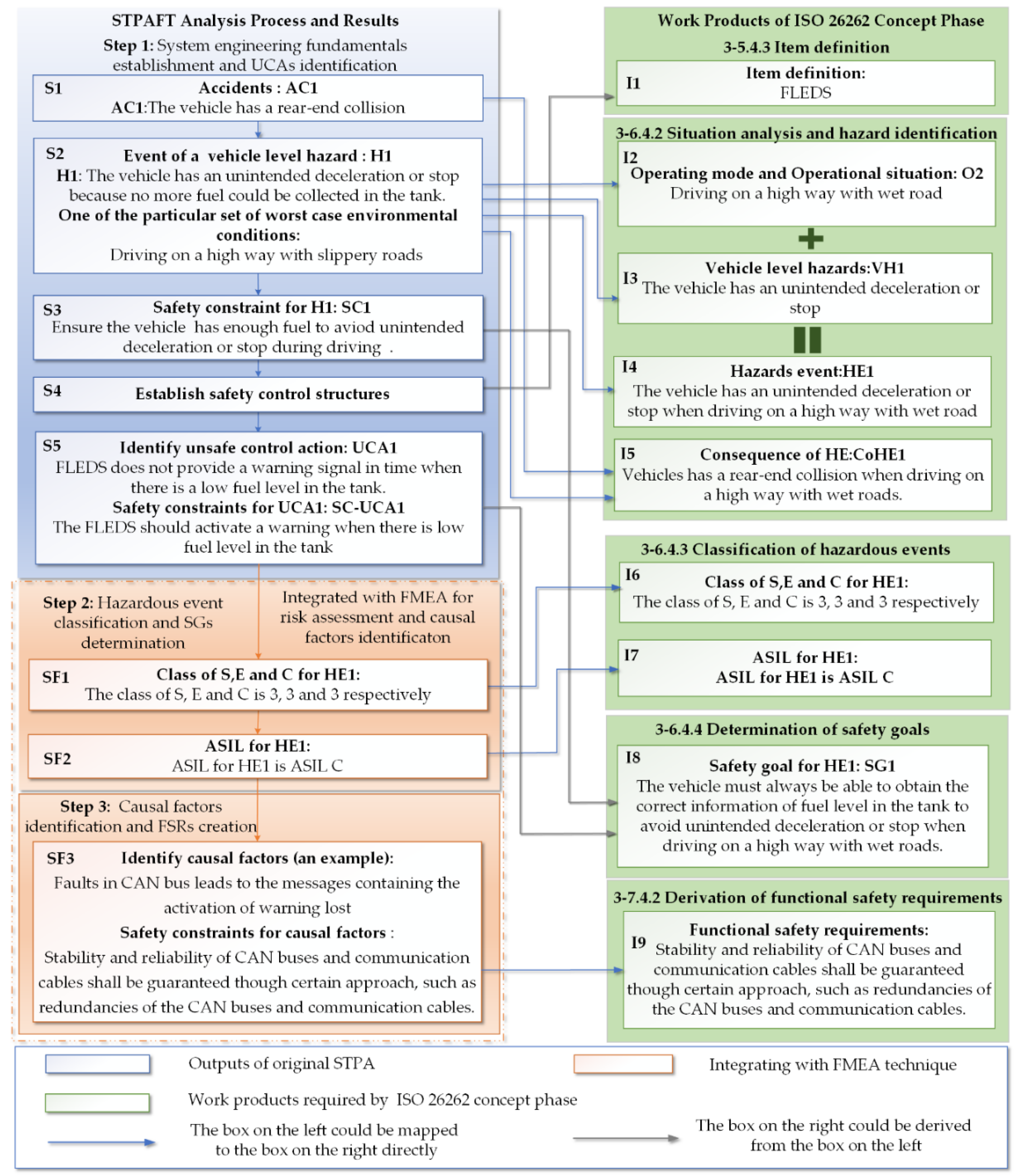
4.2. Step 1: System Engineering Fundamentals Establishment and UCAs Identification
4.2.1. System Engineering Fundamentals Establishment
- Define the “loss” of the system accident in STPA with limitation to the scope of harm defined by ISO26262 to be analyzed.
- Identify system-level hazards leading to the accidents and corresponding operating modes and operational situations from the descriptions of identified system-level hazards.
- Determine corresponding vehicle-level SCs which could be used to support the SGs determination subclause of ISO26262, as the SGs are high-level requirements too. However, the SGs in ISO26262 are more specific than the SCs of the same level in STPA [9].
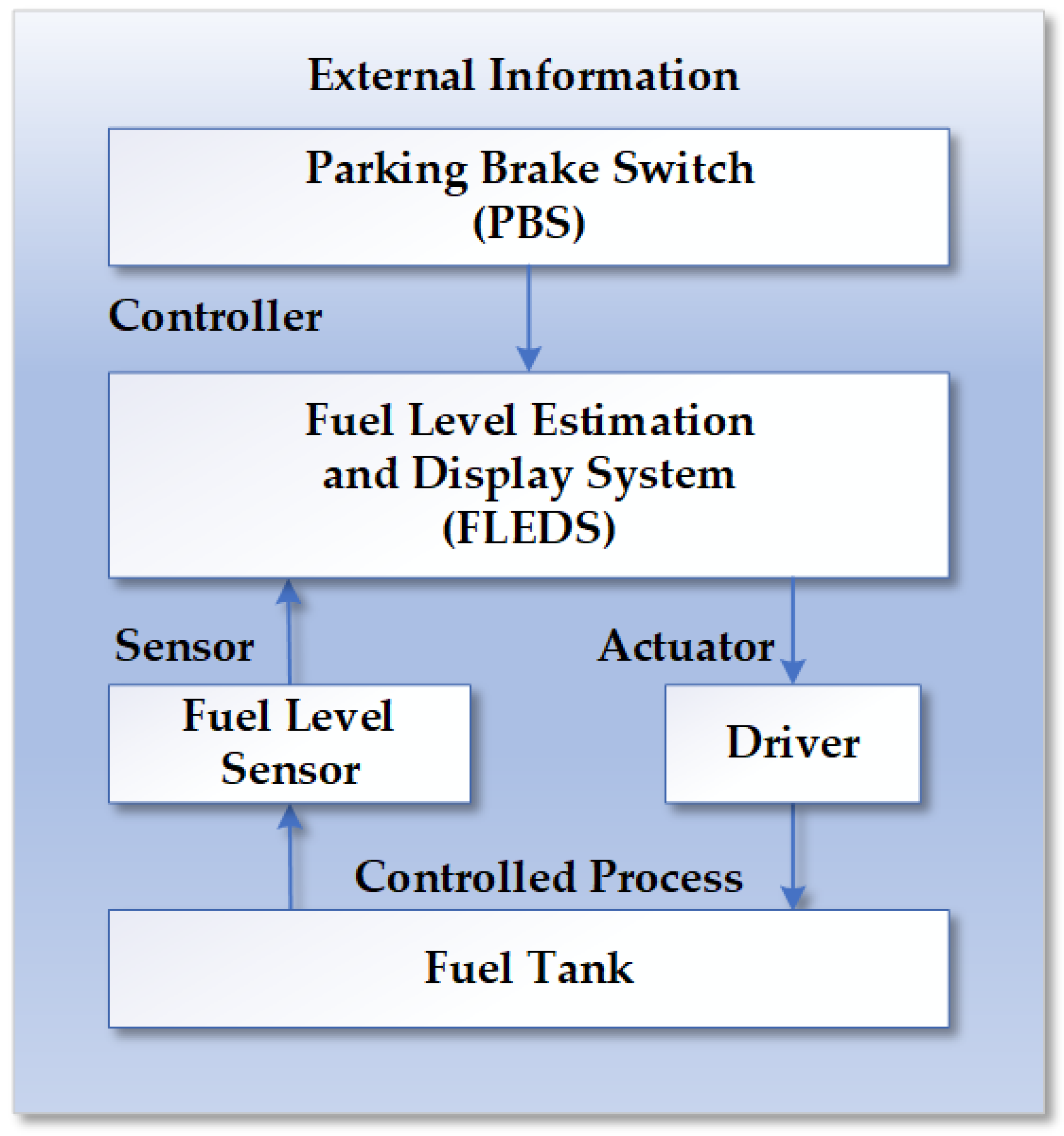
- Draw the safety control structure of the system to identify the potential UCAs leading to the system-level hazards. The control structure diagram shows the boundary of the system under analysis and its interface, and information it contains can be used to define an item.
4.2.2. UCAs Identification
- Identify the UCAs leading to system-level hazards identified in the last step according to the four categories [3] (a control action not provided, a control action provided incorrectly, a control action provided at wrong timing/order, and a control action stopped too soon/applied too long) by examining the safety control structure. Information of UCAs could be helpful in the determination of operating modes, operational situations and the controllability for each hazardous event.
- Corresponding SCs could be determined by adding leading words like “should” or “must” in the description of UCAs.
4.3. Step 2: Hazardous Events Classification and SGs Determination
- Turn the SCs for system-level hazards determined above into the SGs for each hazardous event corresponding to their ASILs.
4.4. Step 3: Causal Factors Identification and FSRs Creation
- With the help of the FMEA technique and the guide words provided by STPA [37], the identification of possible causal factors becomes more detailed at the components level. In order to make better use of FMEA, a functional structure with more details of the system under analysis should be created.
- Generate corresponding SCs for causal factors identified. Since SCs for UCAs and causal factors are all used to describe how to avoid or mitigate hazards, they could be mapped with FSRs of ISO26262.
- Turn the SCs into corresponding FSRs according to the requirements in the 7.4 subclause in ISO26262 Part 3 [6].
5. Case Study
5.1. The FLEDS
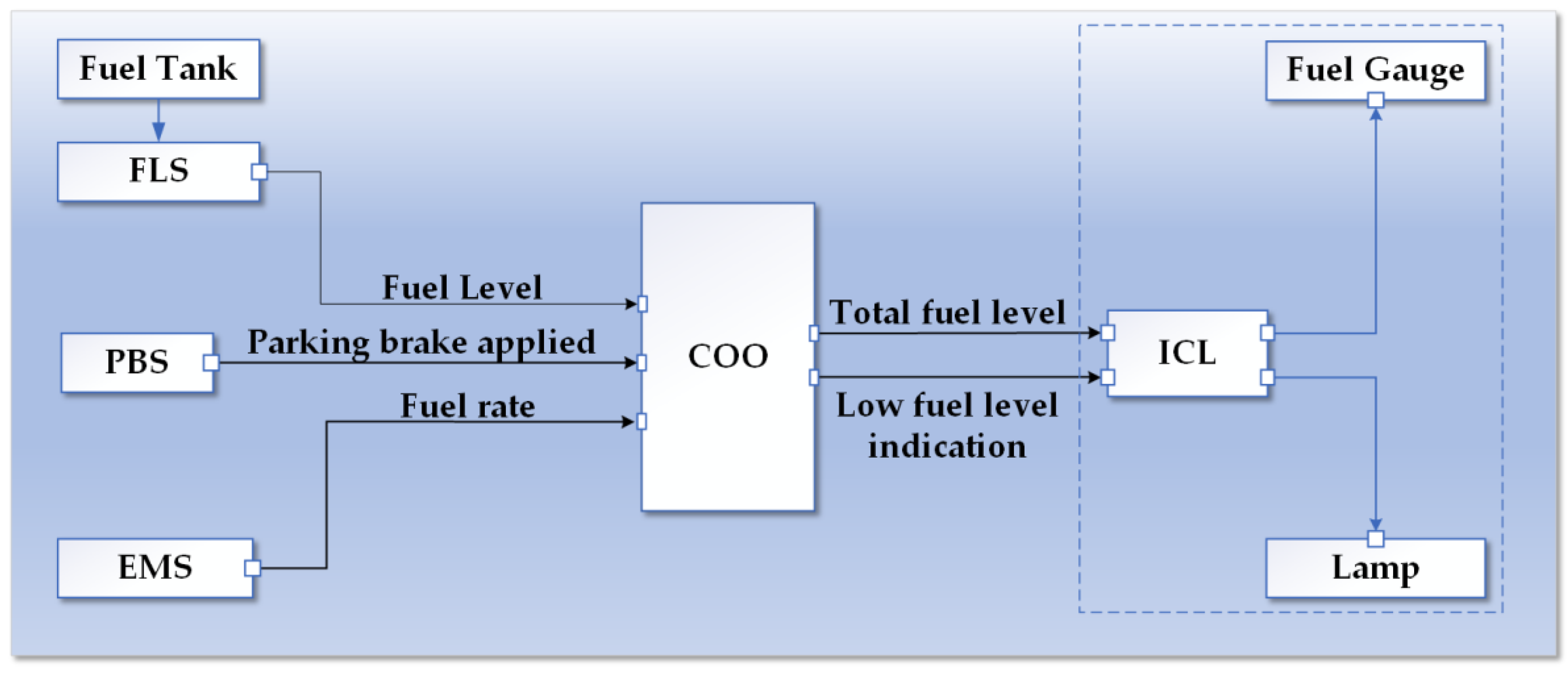
- Engine management system ECU (EMS) is responsible for all the engine related functions.
- The function of instrument cluster ECU system (ICL) is to display indications to the driver, such as warning lamps.
- Coordinator ECU system (COO) is the core ECU of FLEDS and responsible for all functions related to the fuel level calculation. Three inputs are required by COO. They are:
- -
- Fuel level signal from fuel level sensor (FLS)
- -
- Fuel rate signal from EMS
- -
- Parking brake status from parking brake switch (PBS)
5.2. Applying STPAFT
5.2.1. System Engineering Foundations Establishment
5.2.2. UCAs Identification
5.2.3. Classification of Hazardous Events and Determination of ASIL
- Fill CA1, CA2, UCA1, VH1, AC1 and possible operational situations into corresponding columns of FMEA in Table 5.
- Determine the ASIL for each hazardous event identified, taking HE1 as an example. As mentioned above, HE1 identified could be classified with two factors (S and E). The controllability for each hazardous event could be determined by the operational situations together with UCAs identified. The hazard events HE1 is a rear end collision on a highway with wet roads, which could cause fatal injuries, so the severity is determined as S3.
- Probability of exposure could be E3, medium probability. According to the operating modes and operational situation O1: driving on a highway with wet roads, and the unsafe control action UCA1: The FLEDS does not provide a warning signal when there is a low fuel level; the situation is difficult to control or uncontrollable, so the controllability is assigned as C3. Therefore, the ASIL of the hazardous event HE1 could be determined as ASIL C. The ASILs for VH1 under different operational situations are represented in Table 5.
- Formulate SGs according to each corresponding ASIL, still taking HE1 as an example. The SG for HE1 could be formulated according to SC-1 as SG.1: The vehicle must always provide correct information about the current fuel level in the tank to avoid unintended deceleration or stop when driving on a highway with wet roads.
5.2.4. Causal Factors Identification and FSRs Creation
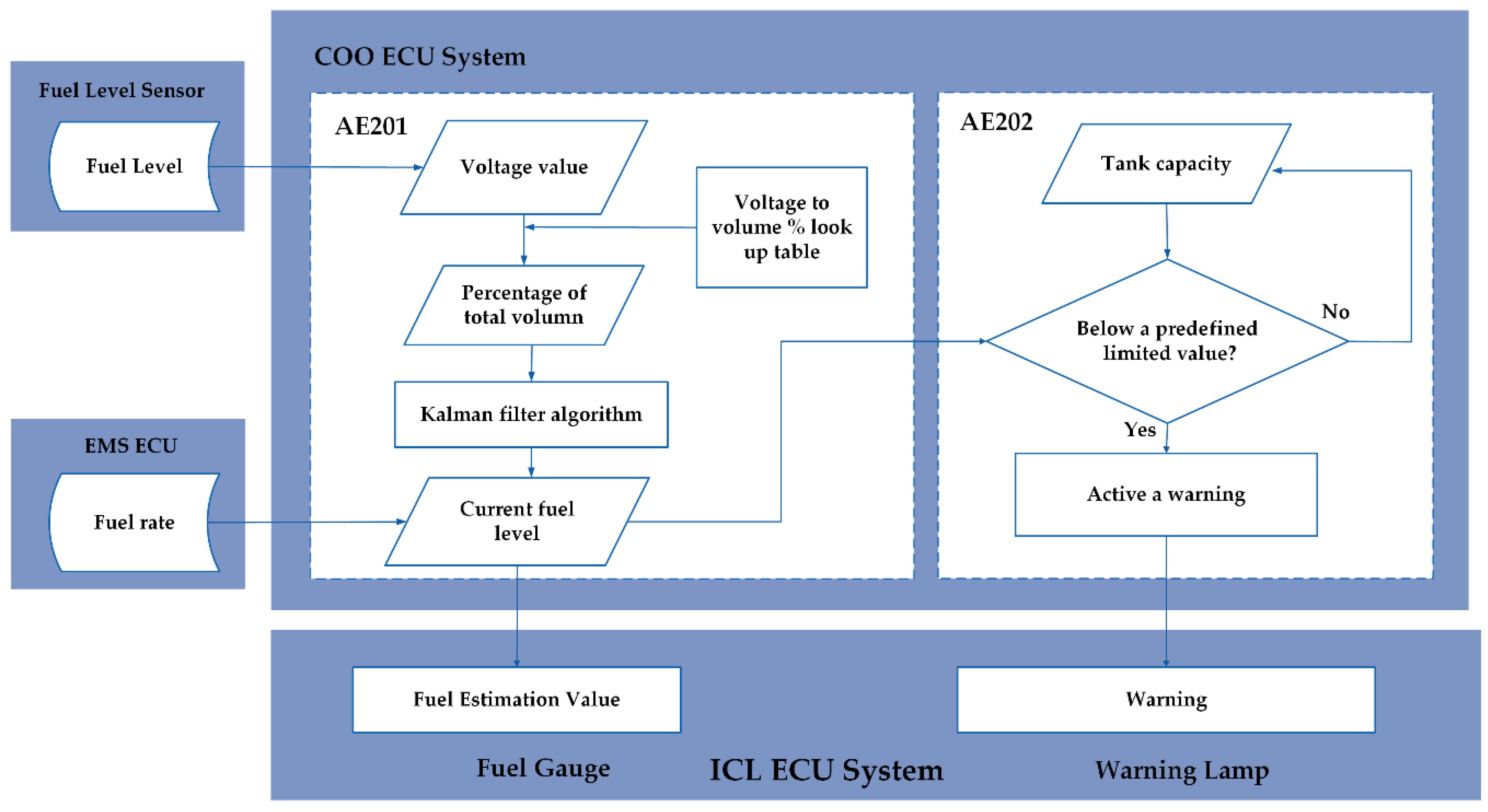
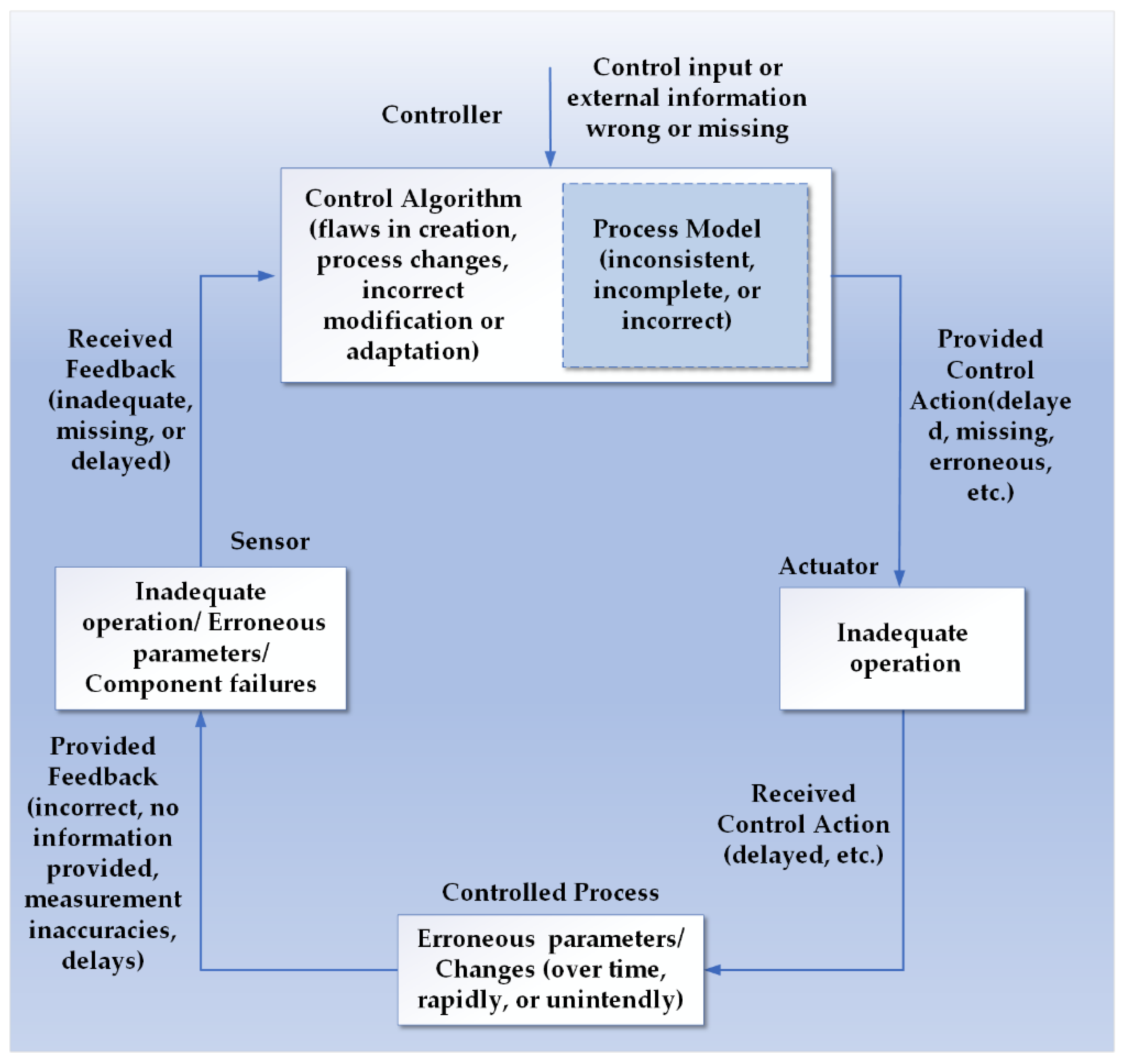
- In order to determine how each UCA could happen using FMES, a detailed structure of the FLEDS is illustrated in Figure 8. We use Figure 8 and the guide words for causal factors in Figure 9 [39] to identify possible causal factors leading to UCAs. With the focus of FMEA on the lowest level components, we can identify the causal factors more systematically, so more detailed safety constraints could be derived, which is conducive to the refinement of FSR.
- We use a hierarchical structure to describe the identified causal factors for each UCA in Table 6, in which “①” represents the highest level and “⑤” represents the lowest. This hierarchical structure presents how unsafe interactions, errors and failures propagate through the system and lead to UCAs. The most important thing is that the hierarchical structure of causal factors would be of great benefit for the allocation of FSRs to the system architecture design.
- Next, the SCs for causal factors are generated and the results of this step will be used to build the functional safety concept and determine the FSRs. The primary intention of the presentation of all the SGs and FSRs derived from SCs in this section are to illustrate how a comprehensive set of requirements could be derived from STPAFT analysis results.
- SC.CF.1: The input signals for estimating the total fuel level shall be good status (meaning the signals are in the range and correct).
- SC.CF.1-1: The FLS shall always keep running normally, and measure fuel level data accurately.
- SC.CF.1-2: The EMS shall always calculate the fuel rate correct.
- SC.CF.2: The input parameters used for estimation of the total fuel level shall be of good status; a replacement value shall be considered and kept.
- SC.CF.2-1: The correct parameters of FLS shall be set.
- SC.CF.2-2: The correct parameters of the fuel tank shall be set.
- SC.CF.3: The measured fuel level signal shall be filtered to avoid the fuel level changing rapidly in some situations, such as driving in long curves, hills and slopes.
- SC.CF.4: The algorithm for total fuel level estimation shall be designed appropriately and a feedback should be set to avoid the deviation of more or less than a permissible error when there are erroneous or unavailable input signals or parameters.
- SC.CF.4-1: The mapping of voltage to volume shall be correct.
- SC.CF.5: When the estimated fuel level reaches a limit of the measurable volume in the tank, the low fuel level warning shall be provided one time.
- SC.CF.6: The ICL shall always function properly, including the gauge and the lamp.
- SC.CF.7: Stability and reliability of Controller Area Network (CAN) buses and communication cables shall be guaranteed through certain approaches, such as redundancies of the CAN buses and communication cables.
- SC.CF.8: The battery shall have enough capacity and ensure power supply continuous and reliable. The electrical connections between the battery and ECUs shall be stable.
- FSR1: The input signals for estimating the total fuel level shall be good status (meaning the signals are in the range and correct). Considered input signals are: fuel level, fuel rate, and parking brake applied. In case input signals are not of good status, a replacement value shall be considered.
- FSR2: The input parameters used for estimation of the total fuel level shall be of good status; a replacement value shall be considered and kept. Considered input parameters are sensor parameters and tank parameters.
- FSR3: The measured fuel level signal shall be filtered to avoid rapid fuel level changes in some situations, such as driving in long curves, hills and slopes.
- FSR4: The algorithm for total fuel level estimation shall be designed appropriately and use feedback to gain information that should be adjusted in a way that will not result in a deviation of more or less than a permissible error when there are erroneous or unavailable input signals or parameters.
- FSR5: Stability and reliability of CAN buses and communication cables shall be guaranteed through certain approaches, such as redundancies of the CAN buses and communication cables.
- FSR6: When the estimated fuel level reaches below the predetermined limit value, the low fuel level warning should warn one time.
- FSR7: There shall be fault detection strategies for hardware in the FLEDS such as the lamp, gauge, and the battery, etc., and shall active warnings when they go wrong. If the FLEDS lose its function, there shall be certain approaches for the driver to obtain the fuel level value.
6. Discussion
7. Conclusions and Future Work
Author Contributions
Funding
Conflicts of Interest
References
- Flemming, C. Safety-Driven Early Concept Analysis and Development. Ph.D. Thesis, Massachusetts Institute of Technology, Cambridge, MA, USA, 2015. [Google Scholar]
- Suo, D.; Yako, S.; Boesch, M.; Post, K. Integrating STPA into ISO26262 Process for Requirement Development; Safety of the Intended Functionality; SAE: Washington, DC, USA, 2017. [Google Scholar] [CrossRef]
- Leveson, N. Engineering a Safer World; MIT Press: Cambridge, MA, USA, 2012. [Google Scholar]
- Leveson, N. Completeness in formal specification language design for process-control systems. In Proceedings of the Third Workshop on Formal Methods in Software Practice, Portland, OR, USA, August 2000; pp. 75–87. [Google Scholar]
- Leveson, N. A new accident model for engineering safer systems. Saf. Sci. 2004, 42, 237–270. [Google Scholar] [CrossRef]
- ISO. 26262: Road Vehicles—Functional Safety, International Organization for Standardization; ISO: Geneva, Switzerland, 2018. [Google Scholar]
- Sundaram, D.; Vernacchia, P.; Wagner, M.S.; Thomas, J.; Placke, S. Application of STPA to an Automotive Shift-by-Wire System; STAMP Workshop: Cambridge, MA, USA, 2014. [Google Scholar]
- Haneet, S.M.; Thomas, B.; Sudeep, P. Application of systems theoretic process analysis to a lane keeping assist system. Reliab. Eng. Syst. Saf. 2017, 167, 177–183. [Google Scholar]
- Abdulkhaleq, A.; Daniel, L.; Stefan, W.; Jürgen, R.; Norbert, B.; Ludwig, R.; Thomas, R.; Hagen, B. A Systematic Approach Based on STPA for Developing a Dependable Architecture for Fully Automated Driving Vehicles. Procedia Eng. 2017, 179, 41–51. [Google Scholar] [CrossRef]
- Abdulkhaleq, A.; Wagner, S. Experiences with Applying STPA to Software-Intensive Systems in the Automotive Domain. In Proceedings of the 2013 STAMP Conference at MIT, Boston, MA, USA, 26–28 March 2013. [Google Scholar]
- Abdulkhaleq, A.; Wagner, S. A software safety verifification method based on system-theoretic process analysis. In Proceedings of the International Conference on Computer Safety, Reliability, and Security, Delft, The Netherlands, 22–25 September 2014; Springer: Berlin/Heidelberg, Germany, 2014; pp. 401–412. [Google Scholar]
- Abdulkhaleq, A.; Wagner, S.; Leveson, N. A Comprehensive Safety Engineering Approach for Software-Intensive Systems Based on STPA. Procedia Eng. 2015, 128, 2–11. [Google Scholar] [CrossRef]
- Hommes, Q.V.E. Review and Assessment of the ISO26262 Draft Road Vehicle—Functional Safety; SAE Technical Paper 2012-01-0025; ISO: Geneva, Switzerland, 2012. [Google Scholar] [CrossRef]
- Hommes, Q.V.E. Safety Analysis Approaches for Automotive Electronic Control Systems. 2015. Available online: https://www.nhtsa.gov/sites/nhtsa.dot.gov/files/2015sae-hommes-safetyanalysisapproaches.pdf/2015SAE-Hommes-SafetyAnalysisApproaches.pdf (accessed on 22 January 2015).
- Periera, S.; Grady, L.; Howard, J. A system-theoretic hazard analysis methodology for a non-advocate safety assessment of the ballistic missile defense system. In Proceedings of the 2006 AIAA Missile Sciences Conference, Monterey, CA, USA, 14–16 November 2006. [Google Scholar]
- Bladine, A. Systems Theoretic Hazard Analysis (STPA) Applied to the Risk Review of Complex Systems: An Example from the Medical Device Industry. Ph.D. Thesis, MIT, Cambridge, MA, USA, 2013. [Google Scholar]
- Martin, R.; Christian, H. Use of STPA as a diverse analysis method for optimization and design verification of digital instrumentation and control systems in nuclear power plants. Nucl. Eng. Des. 2018, 331, 125–135. [Google Scholar]
- Fleming, C.H.; Spencer, M.; Thomas, J.; Leveson, N.; Wilkinson, C. Safety assurance in NextGen and complex transportation systems. Saf. Sci. 2013, 55, 173–187. [Google Scholar] [CrossRef]
- Hu, J.; Zheng, L.; Xu, S. Safety analysis of wheel brake system based on STAMP/STPA and Monte Carlo simulation. J. Syst. Eng. Electron. 2018, 29, 1327–1339. [Google Scholar]
- Mogles, N.; Padget, J.; Bosse, T. Systemic approaches to incident analysis in aviation: Comparison of STAMP, agent-based modelling and institutions. Saf. Sci. 2018, 108, 59–71. [Google Scholar] [CrossRef]
- Wang, Y.; Sun, Y.; Li, C. Aircraft flight safety analysis and evaluation based on IDAC-STPA model. Syst. Eng. Electron. 2019, 41, 1056–1062. [Google Scholar]
- Wang, Y.; Wang, L.; Hu, J.; Zhou, Y. Modeling and analysis of IMA inter-partition communication safety requirement based on STPA. In Proceedings of the 2017 8th IEEE International Conference on Software Engineering and Service Science (ICSESS), Beijing, China, 24–26 November 2017; pp. 284–287. [Google Scholar]
- Yang, Z.; Lim, Y.; Tan, Y. An Accident Model with Considering Physical Processes for Indoor Environment Safety. Appl. Sci. 2019, 9, 4732. [Google Scholar] [CrossRef]
- Bolbot, V.; Theotokatos, G.; Boulougouris, E.; Psarros, G.; Hamann, R. A Novel Method for Safety Analysis of Cyber-Physical Systems—Application to a Ship Exhaust Gas Scrubber System. Safety 2020, 6, 26. [Google Scholar] [CrossRef]
- Banda, O.A.V.; Goerlandt, F.; Salokannel, J.; van Gelder, P.H. An initial evaluation framework for the design and operational use of maritime STAMP-based safety management systems. WMU J. Marit. Aff. 2019, 18, 451–476. [Google Scholar] [CrossRef]
- Zhou, Z.; Zi, Y.; Chen, J.; An, T. Hazard Analysis for Escalator Emergency Braking System via System Safety Analysis Method Based on STAMP. Appl. Sci. 2019, 9, 4530. [Google Scholar] [CrossRef]
- Nan, Q.; Liang, M. Safety Requirements Analysis for a Launching Control System Based on STPA. In Proceedings of the 2019 IEEE International Conference on Mechatronics and Automation (ICMA), Tianjin, China, 4–7 August 2019; pp. 1201–1205. [Google Scholar]
- Jiang, W.; Han, W.; Zhou, J.; Huang, Z. Analysis of Human Factors Relationship in Hazardous Chemical Storage Accidents. Int. J. Environ. Res. Public Health 2020, 17, 6217. [Google Scholar] [CrossRef] [PubMed]
- Feng, T.; Wang, L.; Hu, J.; Chen, M. A Safety Analysis Method for FGS Based on STPA. In Advances in Intelligent, Interactive Systems and Applications. IISA 2018. Advances in Intelligent Systems and Computing; Xhafa, F., Patnaik, S., Tavana, M., Eds.; Springer: Cham, Switzerland, 2018; Volume 885, pp. 936–944. [Google Scholar]
- Schmid, D. Pilot Homicide-Suicide: A System-Theoretic Process Analysis (STPA) of Germanwings GWI18G. In Advances in Human Aspects of Transportation. AHFE 2018. Advances in Intelligent Systems and Computing; Stanton, N., Ed.; Springer: Cham, Switzerland, 2019; Volume 786. [Google Scholar]
- Hardy, K.; Guarnieri, F. Using STAMP in the Risk Analysis of a Contaminated Sediment Treatment Process. In Safety Dynamics. Advanced Sciences and Technologies for Security Applications; Guarnieri, F., Garbolino, E., Eds.; Springer: Cham, Switzerland, 2019. [Google Scholar]
- Samadi, J.; Garbolino, E. Systemic Risk Management Approach for CTSC Projects. In Safety Dynamics. Advanced Sciences and Technologies for Security Applications; Guarnieri, F., Garbolino, E., Eds.; Springer: Cham, Switzerland, 2019. [Google Scholar]
- Yang, P.; Karashima, R.; Okano, K. Automated inspection method for an STAMP/STPA-fallen barrier trap at railroad crossing. Procedia Comput. Sci. 2019, 159, 1165–1174. [Google Scholar] [CrossRef]
- MIL-STD-1629A. Procedures for Performing a Failure Mode, Effects and Criticality Analysis; U.S. Department of Defense: Washington, DC, USA, 1980.
- I.E.C. 60812: 2018. Analysis Techniques for System Reliability-Procedure for Failure Mode and Effects Analysis (FMEA). Available online: http://www.iec.ch (accessed on 10 August 2018).
- Monkhouse, H.; Habli, I.; Mcdermid, J. The Notion of Controllability in an autonmous vehicle context. In CARS 2015-Critical Automotive applications; Robustness & Safety: Paris, France, 2015. [Google Scholar]
- Thomas, J. Extending and Automating a Systems-Theoretic Hazard Analysis for Requirements Generation and Analysis. Ph.D. Thesis, Massachusetts Inst. Technol., Cambridge, MA, USA, 2013. [Google Scholar]
- Dardar, R. Building a Safety Case in Compliance with ISO26262 for Fuel Level Estimation and Display System. Master’s Thesis, Mälardalen University, School of Innovation, Design and Engineering, Västerås, Sweden, 2014. [Google Scholar]
- Rastayesh, S.; Bahrebar, S.; Blaabjerg, F.; Zhou, D.; Wang, H.; Dalsgaard Sørensen, J. A System Engineering Approach Using FMEA and Bayesian Network for Risk Analysis—A Case Study. Sustainability 2020, 12, 77. [Google Scholar] [CrossRef]

| Foundations | ISO26262 HARA | STPA |
|---|---|---|
| Characteristics | Focus hazards on only component failures. HARA and determination of ASIL are used to determine SGs for the item. | Have a broader scope of hazards causes. View safety as a control problem. Use an hierarchical safety structure to describe a system and explain why accidents occur. Do not estimate risk. |
| Application Phase | Applicable in the development stage a system, with little known about the detail design. | Assumed to be used in any stages within the whole life cycle of a system, especially in the early stage of the development process. |
| Objectives | Identify and classify hazardous events. Formulate SGs and corresponding ASIL, for each hazardous event | Identify reasons for inadequate control or enforcement of safety related constraints. |
| Output Results | Hazardous events and their classifications, SGs and associated ASILs | Accidents and associated hazards of a system, UCAs, SCs to be enforced |
| Terminologies | STPA | ISO26262 |
|---|---|---|
| Accident | Events leading to loss result from lack of enough control and enforcement of SCs | Not specifically defined |
| Hazard | The combination of a system state or set of conditions and a specific set of worst-case environmental conditions, will lead to an accident | Potential source of physical injury or damage to the health of persons caused by malfunctioning behavior of the item |
| Harm | Not specifically defined | Physical injury or damage to the health of person |
| Failure | A component’s (or system’s) non-performance or inability to perform as expected or designed. | Termination of an intended behavior of an element or an item due to a fault manifestation |
| Operation Situations | Not specifically defined | Scenarios that may occur within the life of a vehicle |
| Operating modes | Not specifically defined | Perceivable functional state of an item or element |
| Hazardous event | Not specifically defined | The result of integrating a hazard with an operational situation |
| ASILs | Not specifically defined | Levels used to specify safety measures and necessary requirements of an element or item for avoiding unreasonable residual risk |
| Safety Constraints (System Level) | System-level safety requirements to prevent hazards from leading to accidents and ensure safety | Not specifically defined |
| Safety Goals | Not specifically defined | Top-level safety requirements for an item as a result of vehicle-level HARA, expressed as functional objectives |
| Malfunctioning Behavior | Not specifically defined | An item’s failure or unintended behavior with respect to its design intent |
| Unsafe control actions (UCAs) | Inadequate control actions within four types leading to hazards | Not specifically defined |
| Causal Factors | Scenarios that could explain how inadequate control actions might occur | Not specifically defined |
| SCs for UCAs and Causal Factors | Safety requirements derived from the identified UCAs and corresponding causal factors | Not specifically defined |
| Control Action | Not Provide | Provide But Incorrect | Provide at Wrong Time/Order |
|---|---|---|---|
| Provide a warning signal | UCA1: No warning signal provided | … | |
| Supply the current fuel level value | UCA2-1: No fuel level supplied | UCA2-2: Supplied but too high | … |
| SC.UCA1 | The FLEDS should activate a warning to indicate the driver when there is a low fuel level in the tank |
| SC.UCA2-1 | The FLEDS shall always indicate the total fuel level in the tank when driving. |
| SC.UCA2-2 | The deviation of the fuel level estimation by FLEDS shall not exceed the preset allowable deviation from the actual volume in the tank. |
| Function | Failure Modes (UCAs) | Cause (CFs) | Actions (SCs) | Effect | ||||||
|---|---|---|---|---|---|---|---|---|---|---|
| Accident | System-Level Hazard | Operational Situations | S | E | C | ASIL | ||||
| Provide a warning to indicate the driver when there is a low fuel level | The FLEDS does not provide a warning to indicate the driver when there is a low fuel level in the tank. | Shown in Section 5.2.4 | AC1 | H1 | Highway with wet roads | 3 | 3 | 3 | C | |
| City driving, snow and ice driving speed 50km/h | 3 | 2 | 3 | B | ||||||
| Supply the current fuel level to the driver | The FLEDS does not supply a fuel level to a driver. | |||||||||
| City driving slippery road, high traffic | 2 | 3 | 2 | A | ||||||
| The fuel level supplied by FLEDS is much higher than the actual level. | ||||||||||
| 1Free way | 3 | 2 | 2 | A | ||||||
| UCAs | Causal Factors | ||||
|---|---|---|---|---|---|
| The fuel level supplied by FLEDS is much higher than the actual level. | ① The gauge has a mechanical fault | ||||
| ① The gauge function in ICL has bugs | |||||
| ① Incorrect estimation of fuel level by Kalman filter | ② Incorrect fuel level | ③ Incorrect FLS value | ④ Electrical fault in FLS | ||
| ④ Mechanical fault in FLS | |||||
| ③ Incorrect calculation of tank capacity | ④ Tank parameter set incorrectly | ||||
| ④ Incorrect FLS parameters | |||||
| ③ Incorrect mapping of voltage to volume % | ④ Fault in mapping look up table | ||||
| ② Incorrect fuel rate | ③ The calculations of fuel rate by EMS is incorrect | ||||
| The FLEDS does not supply a fuel level to a driver. | 2460 The gauge function in ICL has bugs | ||||
| ① No total fuel level received by ICL | ② Problems in COO | ③ Hardware fault in COO | |||
| ③ No power supply fed to COO | ④ Fault in the power supply | ||||
| ④ There is a fault in the power cable between COO and power supply | |||||
| ② Communication problem between COO and ICL | ③ Cut in communication cable | ||||
| ③ CAN message that has total fuel level lost | ④Fault in CAN bus | ||||
| ① Hardware fault in ICL | |||||
| ① The gauge has a mechanical fault | |||||
| The FLEDS does not provide a warning to indicate the driver when there is a low fuel level in the tank. | ① Communication problem between COO and ICL | ② Cut in communication cable | |||
| ② Message that contains the activation of warning is lost | ③ Fault in CAN bus | ||||
| ① Fault in warning lamp | |||||
| ① Bug in warning lamp function in ICL | |||||
| ① The low fuel level warning function in COO outputs incorrectly | ② Erroneous value of tank size | ||||
| ② Kalman filter estimates fuel level erroneously | ③ Erroneous fuel level | ④ Incorrect mapping of voltage to volume % | ⑤ Fault in mapping look up table | ||
| ④ The fuel level value is filtered incorrectly | ⑤ Low pass filter equation has faults | ||||
| ④ Incorrect FLS value | ⑤ Electrical fault in fuel sensor | ||||
| ⑤ Mechanical fault in fuel sensor | |||||
| ④ Errors in the calculation of tank capacity | ⑤ The tank parameters set incorrectly | ||||
| ⑤ Incorrect FLS parameters | |||||
| ③ Fuel rate errors | ④ The calculations of fuel rate by EMS is incorrect | ||||
Publisher’s Note: MDPI stays neutral with regard to jurisdictional claims in published maps and institutional affiliations. |
© 2020 by the authors. Licensee MDPI, Basel, Switzerland. This article is an open access article distributed under the terms and conditions of the Creative Commons Attribution (CC BY) license (http://creativecommons.org/licenses/by/4.0/).
Share and Cite
Chen, L.; Jiao, J.; Zhao, T. A Novel Hazard Analysis and Risk Assessment Approach for Road Vehicle Functional Safety through Integrating STPA with FMEA. Appl. Sci. 2020, 10, 7400. https://doi.org/10.3390/app10217400
Chen L, Jiao J, Zhao T. A Novel Hazard Analysis and Risk Assessment Approach for Road Vehicle Functional Safety through Integrating STPA with FMEA. Applied Sciences. 2020; 10(21):7400. https://doi.org/10.3390/app10217400
Chicago/Turabian StyleChen, Lei, Jian Jiao, and Tingdi Zhao. 2020. "A Novel Hazard Analysis and Risk Assessment Approach for Road Vehicle Functional Safety through Integrating STPA with FMEA" Applied Sciences 10, no. 21: 7400. https://doi.org/10.3390/app10217400
APA StyleChen, L., Jiao, J., & Zhao, T. (2020). A Novel Hazard Analysis and Risk Assessment Approach for Road Vehicle Functional Safety through Integrating STPA with FMEA. Applied Sciences, 10(21), 7400. https://doi.org/10.3390/app10217400


