1. Introduction
Nowadays, piezoelectric devices are very common in a wide range commercial and industrial areas. Piezoelectric devices are used in optomechanical systems, micromanipulators, and robotics [
1,
2]. Typically, piezoelectric actuators are of small size, simple design, and generate micrometer-scale mechanical displacement (from 0.5 μm to 150 μm). Because of the small size and mass, the inertia force of the device is low, and therefore, the response time is short. These features of the piezoelectric actuator allow to achieve good performance and power/volume ratio. It is worth mentioning that the piezoelectric actuator is made from non-magnetic materials and can be used where strong magnetic fields are undesirable to any equipment and should be protected from the additional magnetic noise. Piezoelectric actuators are able to reach extremely high precision with micro- or even nano-resolution and are driven at high-frequency modes that can generate unlimited linear or rotary motion. These features allow to integrate them into a wide variety of applications.
Simple design and uncomplicated working principles allow using piezoelectric devices in industries such as space, satellite communication, and navigation. Specifications for the devices which may be used for space application are rigorous, i.e., small mass and volume, easy integration, and high reliability are only a few of those requirements. Piezoelectric actuators and devices are good candidates for such tasks and may be used for space applications.
However, the majority of piezoelectric actuators and motors are the single degree of freedom (DOF) devices, while there are many applications where several DOF systems are required. Those systems can be assembled using several actuators, but the systems become complicated, and it is challenging to manage errors while combining several single DOF actuators. Moreover, such behavior is not acceptable for the tasks, where the size and weight of the mechanism are limited, and high precision becomes an issue. Oppositely, building a large system requires separate units because of the size limitations of piezoelectric actuators [
3]. However, in this approach, the size of the motor must be designed in a way when a minimum number of elements are needed.
Multi-DOF ultrasonic motors are devices that can set orientation and positioning of the object in any direction. 3DOF piezoelectric actuator, which consists a cylindrical stator and the round-shaped rotor, was designed and developed by Zhao et al. This actuator actuates the longitudinal and bending vibrations when the harmonic driven signal is applied to the piezoelectric rings [
4]. Hassani et al. [
5] designed and investigated a novel pyramidal-shaped three DOF positioning mechanism. This mechanism is made from aluminum alloy, and three piezoelectric actuators are inserted at every 120° angle. Such a mechanism can deliver 3D elliptical movements of the contacting points in space. There are more studies on the investigation of ultrasonic motor (USM) capability to generate a rotational movement of the spherical rotor. Analytical studies of linear piezoelectric unimorph model were described by Smith et al. Wang and Cross modified and improved this analytical model. Lim et al. proposed 3D electromechanical analysis of a piezoelectric unimorph [
6].
Vasiljev et.al. proposed a new design of 3DOF piezoelectric actuator developed to rotate the spherical rotor about three axes [
7]. The rotor is placed on the square shape vibrating frame that is excited by four piezostacks. The elliptical motion of four driving tips is transferred to the rotation of the rotor. The rotation direction of the rotor is controlled by changing the amplitude and phase of the harmonic electric signal of the different piezo stacks.
Li et.al. proposed 3D hybrid piezo electrical drive with spherical rotor which is made using permanent magnetic semi-spheres [
8]. These semi-spheres are hollow and connected together. This sphere is the rotor of the drive. In between the sphere are three piezoelectric disks at 120°. Piezoelectric disks are always in a contact with the inner side of the sphere. When harmonic electric signal is applied for the piezoelectric actuators, running wave is generated and the sphere is rotated. This drive is complex and has many peripheral parts.
Keller et.al proposed 3DOF spherical drive with piezoelectric rotor [
9]. This drive has spherical rotor which is made using piezoelectric material. Electrodes are located on the inner and outer faces of the sphere. This rotor is inserted in a thick aluminum flange, which is the stator of the drive. When an electric driven signal is applied, the sphere deforms into 3D shapes and rotates the sphere. This sphere can rotate around three axes, but the angles are limited.
Lu et.al proposed 3DOF spherical drive with two stators [
10]. These stators are made using four legs which acts like a springs and piezoelectric disk-type transducer. The sphere is compressed between two stators. Those legs also are used for pre-load of the sphere. The drive is compact, but heavy: stators are made using thick metal flanges, four legs are thin and may not keep long time due fatigue.
This paper presents an innovative design concept of 3DOF USM with two ring-shaped piezoelectric transducers. Each piezoelectric transducer is glued on a thin elastic flange and forms a unimorph type actuator which can be excited at higher vibration modes for generation of 3DOF rotary motion of the spherical rotor. Numerical and experimental studies were performed and presented in this paper. This is a continuous research of 3DOF drive that was investigated and published in a previous article [
11]. The aim of this work is to improve accuracy and remove supplementary components from the design.
For the comparison,
Table 1 was added which highlights the differences between proposed USM motor and others mentioned in a paper.
2. Design and Working Principles
The proposed piezoelectric USM consists of two ring-shaped piezoelectric transducers glued on the thin metal flanges that have disc shape (
Figure 1). The spherical rotor is placed in between piezoelectric transducers. Transducers are driven by a harmonic electric signal with the frequency of higher vibration modes of the unimorph structure. The stator of the USM is a composite structure, in which the flanges and piezoelectric transducers are bonded using epoxy resin and are forming two unimorph piezoelectric actuators. This type of actuators has the benefit of generating larger flexural displacements with higher mechanical force and torque, which rotates a sphere. The proposed USM potentially can be used in optomechanical systems, humanoid robotics, military, and space applications [
12].
The basic design idea and structure of the developed USM is presented in
Figure 1a. A spherical rotor (1) is inserted among two unimorph piezoelectric actuators, as presented in
Figure 1b. The motor is symmetrical; therefore, the top and bottom actuators are identical. Piezoelectric ring-shaped transducers are made from hard type PZT-4 ceramics. The piezoceramic rings were polarized in the thickness direction, parallel with Z axis, and electrodes cover the upper and lower surfaces of the piezoelectric transducer. Electrodes on the upper surface are partitioned in 3 sections with an angle of 120° between them. The electrode on the bottom surface is continuous and glued on the flange. Three contact elements (4) are glued on the upper electrode (2) and they are located in the center of each segmented electrode.
When the electric signal makes the piezoelectric transducer vibrate, then the frictional force acting between the contact element and the spherical rotor is generated, and the rotation of the rotor is obtained. Three bolts (5, 6) are used to get the motor assembled. The preload force between contact elements (4) and spherical rotor (1) can be adjusted by turning the nuts (5).
The USM driving scheme and layout of segmented electrodes of the piezoelectric transducer are shown in
Figure 1c. The setup consists of a three-channel signal generator (7) and controller (8). Three pairs of segmented electrodes of the upper and lower transducers are electrically connected to channels A, B, C. The harmonic electric signal is amplified by controller. Only one channel is active at a certain moment and it is used to rotate the sphere. Such setup allows achieving excitation of a specific segment of the piezoelectric actuator and induce movements in elliptical trajectories of the contact element (4).
The operating principle of the proposed USM is provided by the elliptical motion of the excited contact elements (
Figure 1b) when a higher bending mode of the actuator appears. While the driven electric signal is defined at particular frequency and applied for specific electrodes of piezoelectric actuator, the resonant vibrations are excited. Accordingly, the elliptical motion of the contact elements is obtained, and an oblique impact on the surface of the sphere is accomplished. As a result, the directional rotation of the rotor around one particular axis is generated. The rotation speed and torque of the rotor are controlled by the amplitude of the electric signal. The direction of rotation is changed by switching channels of the signal generator and by exiting the particular pair of the segmented electrodes.
3. Numerical Modeling of the Actuator
The 3D simplified model of the unimorph actuator was designed, and numerical simulations were executed. The aim of the simulations was to determine resonant frequencies and vibration modes using three different designs of actuator’s flange. Numerical modeling was performed when the piezoelectric actuator was analyzed as unimorph structure, i.e., a transducer and flange were bonded using epoxy resin, and the other piezoelectric transducer was fixed on the flange using soft rubber spacers. The 3D vibration amplitudes and trajectories of contact points of the actuator were analyzed. All simulations were performed in two steps: firstly, modal analysis was executed, and then, harmonic response studies were performed.
USM actuator consists of a piezoelectric ring-shaped transducer, contact elements, and thin flange. All geometry was designed and prepared using Autodesk Inventor Professional 2018, and COMSOL Multiphysics 5.4 was utilized for the calculations. Preparing models for calculations, only specific components were designed i.e., piezoelectric transducer, contact elements, and thin flange. Other components such as the glue layer, soft rubber spacer, and electrodes, were not included. Piezoelectric ring-shaped transducer dimensions were as follows: outside diameter was 20 mm, inside diameter was 15 mm, and the thickness was 3 mm. PZT-4 hard type piezoceramics was used for the production of piezoelectric transducer. This piezoceramics is widely used for the USM motors [
13,
14,
15].
The disc and triangle-shaped flange were investigated. The thin flanges were made from phosphor bronze C52100 and had the following dimensions: outer diameter was 35 mm, central hole was 15 mm, and thickness was 0.3 mm. Dimensions of the actuators and flanges are presented in
Figure 2. Contact elements are made from friction-resistant material—Aluminum oxide (Al
2O
3). Dimensions of these contact elements were as follows, i.e., width: 1 mm; length: 2.2 mm, and height: 1.5 mm. The properties of used PZT-4 piezoceramic and dimensions of components are presented in
Table 2 [
11,
16,
17,
18,
19,
20].
Modal-frequency analysis was accomplished while the actuator was not clamped, and short circuit boundary condition was applied. Piezoelectric transducer and assembled unimorph actuator with two types of the flanges were analyzed (
Figure 3). The aim of this study was to find out the modal shapes and natural frequencies of the actuator that can be used for rotor driving. Trajectories of the displacements were investigated, these trajectories are on the top contact element, shown in
Figure 4.
Firstly, a modal-frequency analysis of the piezoelectric transducer was performed. Frequency range from 20 to 110 kHz was studied. Results showed that several modes had dominating displacements in axial and radial directions of the ring-shaped transducer. Such type displacements are needed to generate an elliptical 3D motion of contact point. The modal shape of the piezoelectric transducer at resonance frequency 93.2 kHz is presented in
Figure 5.
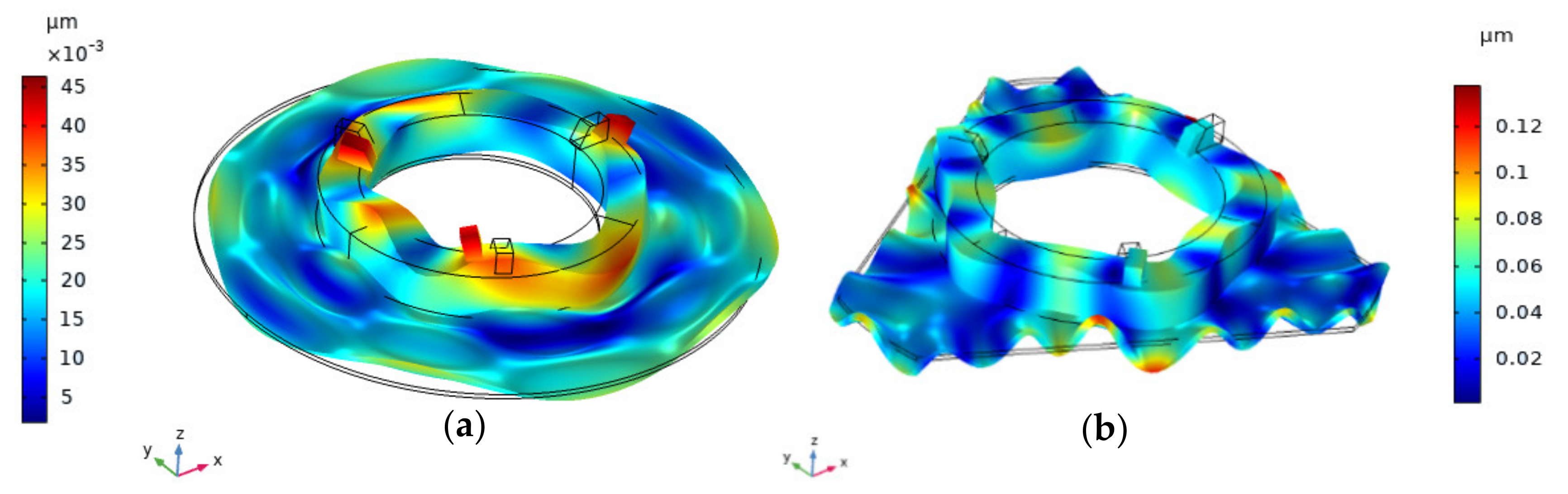
Lastly, modal shapes of unimorph actuator were analyzed when the disc and triangle-shaped flanges were used. The needed modal shapes were determined at the frequencies of 94.8 kHz and 95.3 kHz for the actuators with a disc and triangle-shaped flanges, as shown in
Figure 6. Contact elements are displaced in radial and axial directions; therefore, the contact point moves in the XZ plane and these modes of vibrations and can be used for rotor driving.
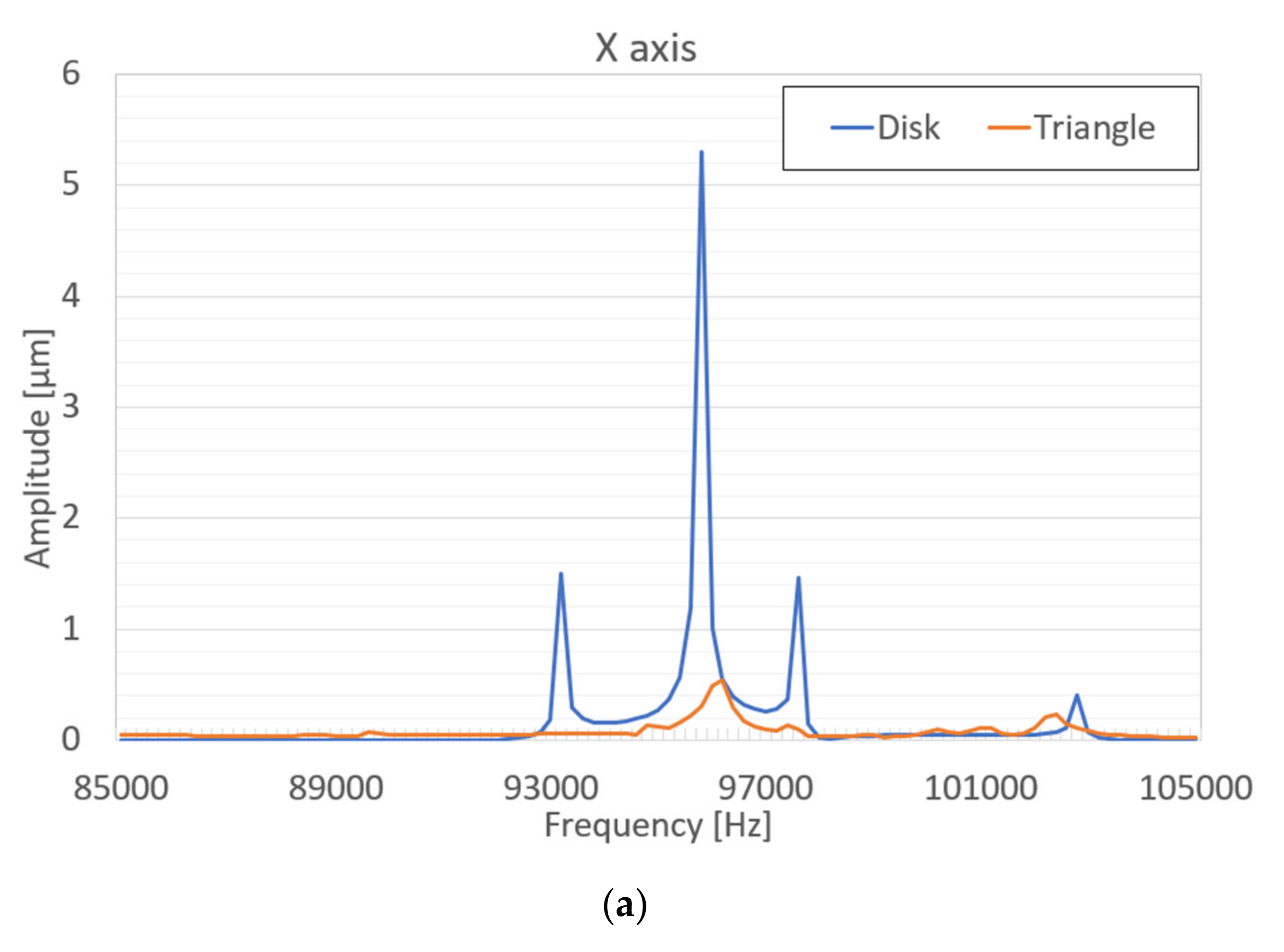
Harmonic response analysis of the actuator was performed as well. The aim of numerical simulations were to determinate the rebound of the contact element and find out its trajectory of motion while voltage is applied to one of the segmented electrodes. An amplitude of driven electric signal was 50 V and this signal was provided for one of the top electrodes while the bottom electrode was grounded. The analysis was performed in a frequency range of 85 kHz–105 kHz, while the solution step was 50 Hz. The piezoelectric actuator has a symmetrical structure. Hence only one segment of the top electrode was excited. Numerical simulation was performed when the actuator had a disc-shaped and triangle-shaped flange, respectively. The displacement amplitudes in X, Y, and Z directions were studied and compared. The results of the harmonic response analysis are presented in
Figure 7 and
Figure 8.
A comparison of the displacement amplitudes of the actuator with disc and triangle-shaped flanges are presented in
Figure 9.
From the graphs, it can be seen that dominant vibrations appear in radial and axial directions, i.e., X and Z accordingly, and the shape of the flange has a big influence on the displacement amplitude. The higher amplitude was determined in the X-axis direction for an actuator with a disc-shaped flange. The value of this displacement is 6.2 µm. Axial displacements in the Z-axis direction is also for an actuator with a disc-shaped flange and equal to 0.92 µm. It must be noted that using a triangle shape for the flange, vibration amplitude is significantly smaller compared with the disc-shaped actuator. The actuator with a disc-shaped flange reaches its resonant peak at 95.8 kHz, while the actuator with a triangle-shaped flange at a frequency of 96.2 kHz. Amplitudes in X and Z directions decrease accordingly with the higher resonant frequencies.
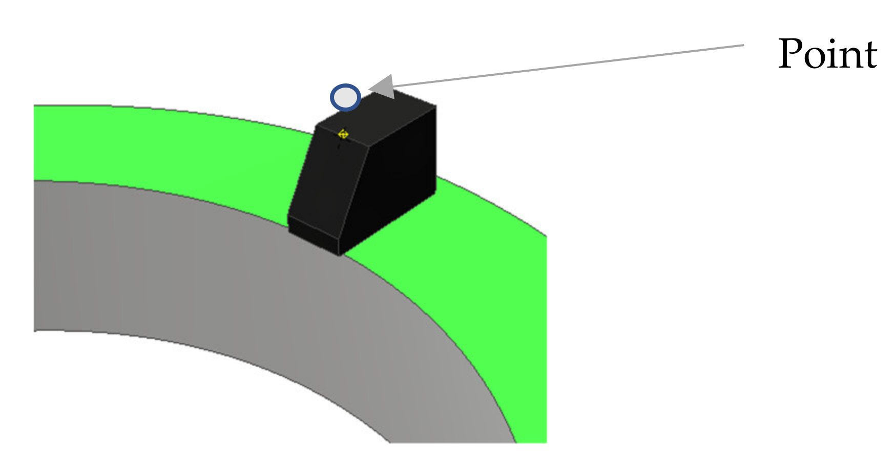
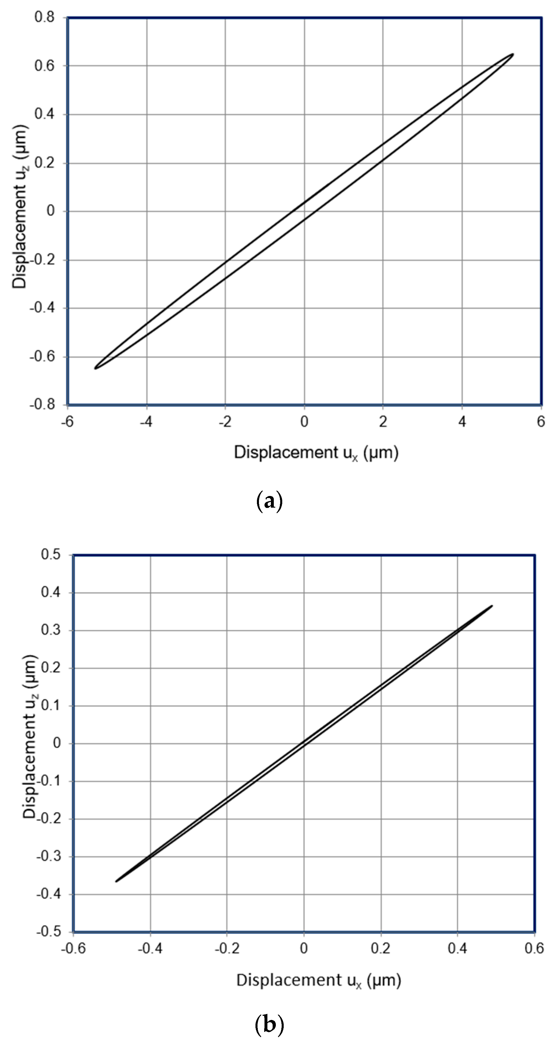
Contact point (
Figure 3) trajectories were calculated in the XZ plane when different flanges of the unimorph actuator were used. Trajectories were analyzed at the vibration frequency of 95.8 kHz and 96.2 kHz for disc-shaped flange triangle-shaped flange, respectively. The results of elliptical movement trajectories are presented in
Figure 10. It can be noticed that trajectories are in elliptical shape, but the length of the major and minor axes are different. Lengths of the ellipsis major and minor axes are shown in
Table 3. From the results can be seen that the longer length of the ellipsis axis has the actuator with the disc-shaped flange. Results from numerical simulations confirmed that elliptical trajectories could be achieved, and that the proposed actuator can be used for USM.
4. Experimental Studies
Experimental studies were accomplished. Three experimental prototypes of the piezoelectric actuator were designed and built for the result validation of the numerical study. One prototype was a ring-shaped transducer attached to the soft rubber base. The other two prototypes were of unimorph-type with the disc and triangle-shaped flanges and piezoelectric ring-shaped transducers bonded using epoxy resin. The piezoelectric material of PZT-4 was used for the transducer, the dimensions and properties of the materials are shown in
Table 1. Laser scanning vibrometer Polytec PSV-500-3D-HV (Waldbronn, Germany) and driving voltage amplifier P200 (FLC Electronics AB, Partille, Sweden) were used for the experimental studies [
21,
22]. The experimental setup is presented in
Figure 11.
An experimental investigation of the dynamic characteristics of the actuators using a Polytec scanner was executed with the following steps: first of all, planar surfaces of the actuators were scanned, and virtual meshes were created. Later, the driven electric signal was determined in a frequency range from 50 to 110 kHz. This signal was amplified by a voltage amplifier and applied for one of the segmented electrodes of the transducer. 3D scanning vibrometer allows a non-contact, optical measuring of the amplitudes of vibrations and defines the operational frequencies of the actuators. The deformations of the scanned actuators are shown in
Figure 12,
Figure 13 and
Figure 14.
Firstly, the piezoelectric transducer without flanges was analyzed. This piezoelectric transducer was glued on soft rubber tape and attached to the steel plate. Soft rubber tape reduces constraints, and piezoelectric transducer can perform closer to its natural frequencies of vibration modes. The setup and vibration mode shape of the piezoelectric transducer is shown in
Figure 12.
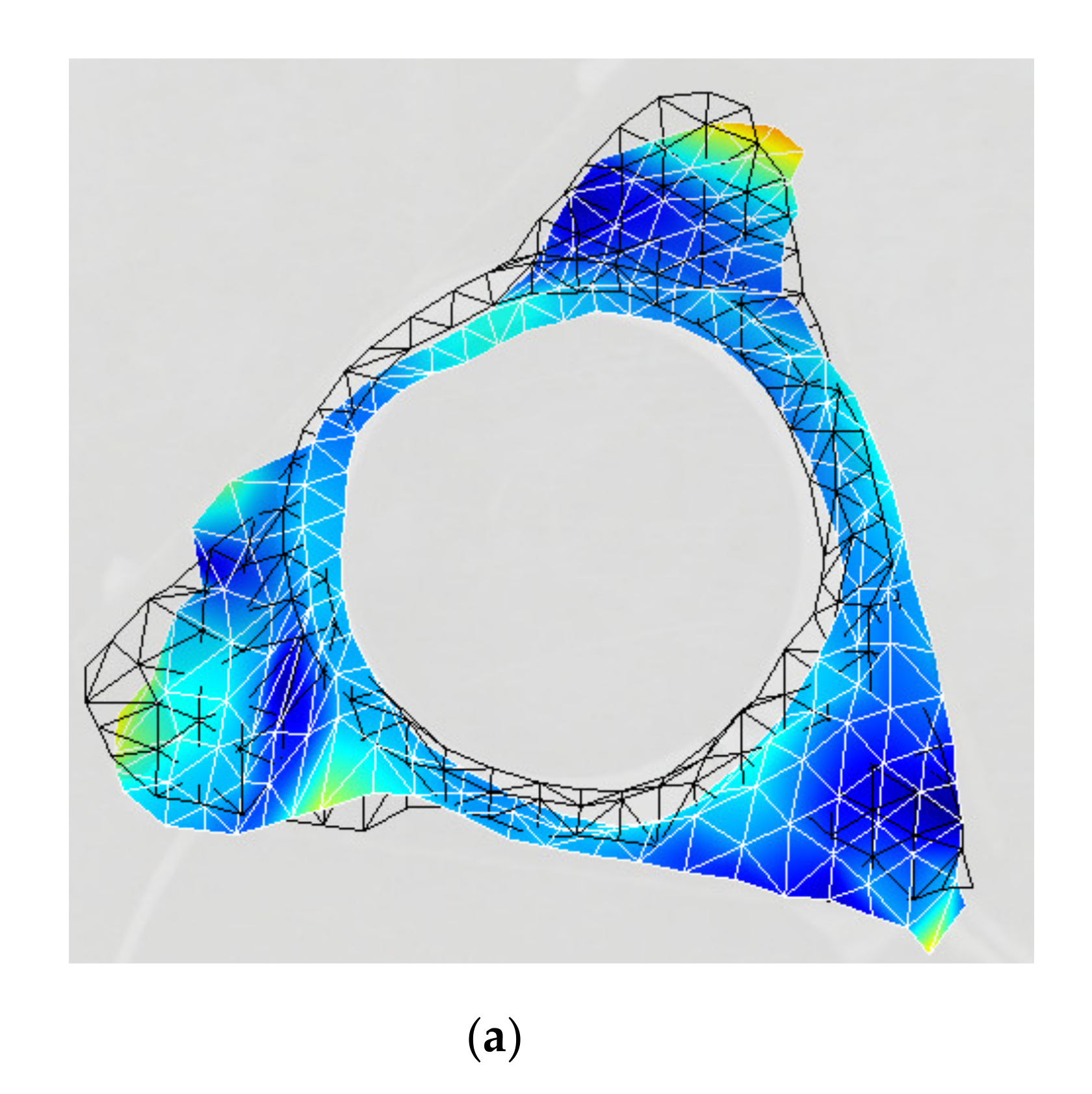
Secondly, an actuator with triangle-shaped flange was measured. The results of measurements are shown in
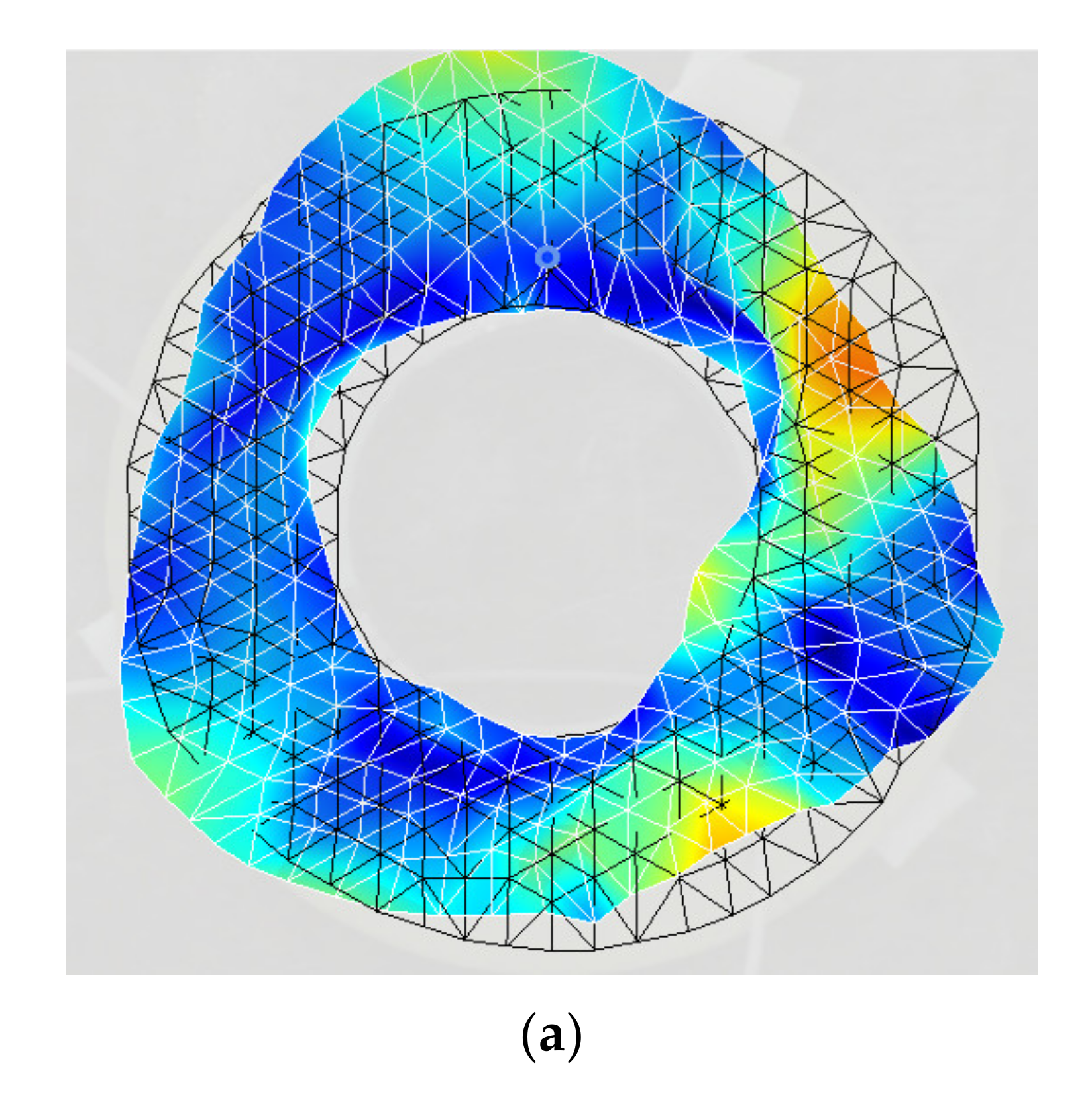
Figure 13 at the vibration frequency of 93.72 kHz. Lastly, an actuator with a disc-shaped flange was analyzed. The results of this analysis show that operational vibration modes are achieved at 94.4 kHz. The vibration mode shape of the actuator with the disc-shaped flange and measured amplitude of vibration versus frequency graph are presented in
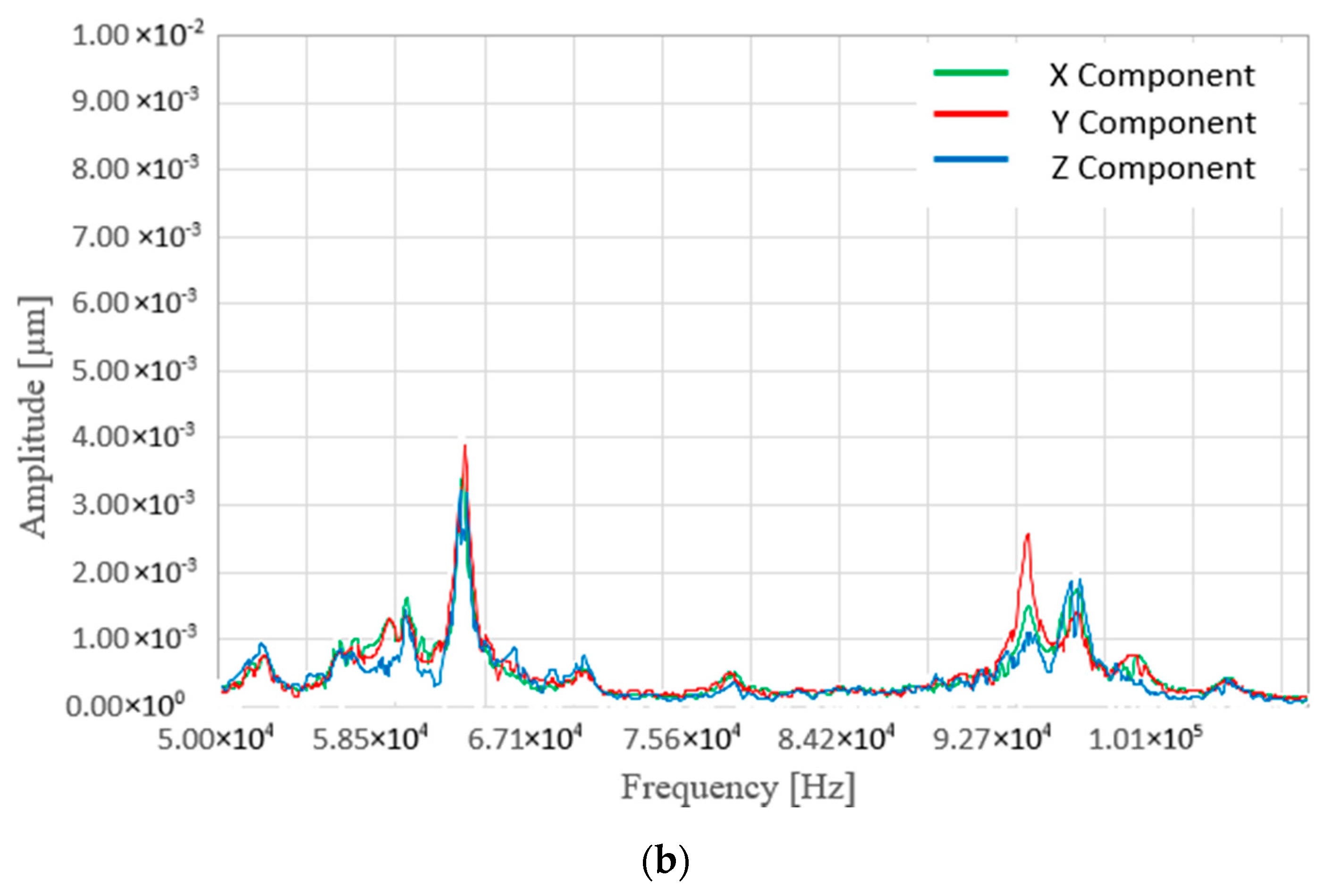
Figure 14.
It could be noticed that deformations of the actuators are similar to what was achieved in numerical simulations. Displacements in Z direction are relatively small compare to X and Y directions, when piezoelectric transducer operates without flange. When the flange is added, the amplitudes in Z direction increases and higher displacements are achieved. This is an important feature of the actuator design, and it crucial for the elliptical trajectories’ generation of the contact point and proper operation of the actuator. Moreover, it can be noticed that results of displacement amplitudes of numerical calculations are similar to experimental studies, actuator with disc-shaped flange is ~1% and with triangle-shaped flange ~3% higher than experimental measurements. The errors can be induced by various causes: slightly different material properties, inaccurate prototypes’ dimensions and others. Deformations of actuators and their oscillation modes during experimental studies are more pronounced and visible in excitation zones than numerical calculations. This could be a reason of additional mass of wire soldering points, not free fixtures, errors of measurements.
Additionally, experiments with the pre-load were performed. Spherical rotor was added and resonance frequencies were measured. During these simulations, resonant frequency was slightly increased and amplitudes slightly reduced. The resonance frequencies (operating frequencies) of the actuators without preload/with preload accordingly are: for disk-shaped configuration is 94.4 kHz/94.5 kHz and for triangle shaped configuration 93.7 kHz/93.9 kHz. Also, the rotation speed of the spherical rotor was measured experimentally. An amplitude of driving electric signal of 70 V was connected to a one electrode of the 3 segmented electrodes. Rotary speed at operating frequency for a disk-shaped actuator was approximately 30 rpm, for a triangle-shaped actuator 27 rpm. The preload of the of the sphere was 0.65 N.


