1. Introduction
The borehole log is a basic record generated through the observation and identification of the rock (mineral) core (or cuttings, rock powder), in which sampling analysis and various tests are conducted based on the borehole [
1]. Because can visually represent the rock formations, ore bodies, and their interrelationships through the borehole, it is the basic form of data collection for compiling geological sections, comprehensive geological maps and 3D geological modeling [
2]. For historical reasons, the borehole logs that are accessible to us are often in paper or photo format.
Based on the existing methods for extracting information from the borehole logs, there are several problems in the traditional process. Firstly, there are a large number of irregular tables in borehole logs, which are connected by polylines. Secondly, there is an amount of geological symbols and technical vocabulary in the geological field, and the traditional optical character recognition (OCR) image recognition method does not identify these complicated shapes with sufficient accuracy. Therefore, the traditional method of image recognition is not suitable for the extraction of information from borehole logs. Even the manual input method is inefficient.
It is essential to extract structured information from the borehole log for further analysis and application based on the borehole data. However, this process is time-consuming and labor-intensive. In order to reduce labor costs, it is urgent to develop automatic extraction technology for borehole log information.
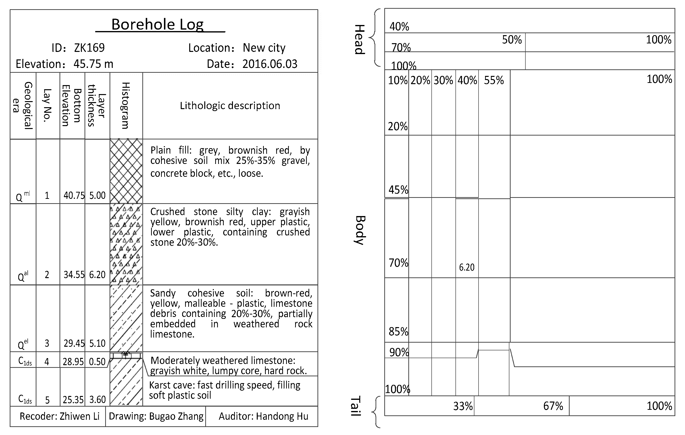
The essence of borehole log information extraction is the content recognition of complicated table graphs. Different from the common table maps, the borehole log has additional features. The two most obvious are the table in the borehole log has a beard phenomenon on the structure (
Figure 1, and there are many professional vocabularies in the content [
3,
4]. In this paper, the automatic extraction of borehole log information is proposed based on the solution of the above problems. A method is proposed for the special problems related to the structure and content of the borehole log.
In order to extract the information from the borehole log, the Hough transform is introduced to recognize the complicated table shapes. After acquiring the grid lines, this paper introduces deep learning and Tesseract to recognize the symbols in geological fields such as (Qel). After a long time training of the final model, the recognition of such complicated symbols can be completed quickly and locally, even on the computer with low configuration.
The rest of this paper is organized as follows:
Section 2 presents the current state of research and problems with this issue. Based on the structural analysis of the borehole log,
Section 3 introduces the overall flow of the proposed method. In
Section 4, the idea and method of segmentation based on corner markers are introduced in detail.
Section 5 introduces the method of text recognition based on deep learning for the borehole log.
Section 7 discusses and summarizes the method presented in this paper.
2. Related Work
The essence of the borehole log is a complicated tabular diagram (it uses a combination of text and symbols in forms), which is concise and easy to read features. For this kind of table diagram, structural analysis and layout understanding are two levels of information extraction. Among them, the structural analysis focuses on the geometry of the table diagrams. The structural analysis mainly includes checking the borehole log at the structural level, such as locating and extracting the table fields, map fields, text fields and other information in the layout. All these elements are the foundation for the next layout understanding [
5]. The layout understanding focuses on the logical structure of the table diagram. It is a logical level analysis of the analyzed complicated layout, which can determine the logical attributes and classification of each region. The purpose of this analysis is to adopt different processing methods for different categories [
6].
Many researchers have carried out in-depth research on the extraction of table map information and proposed a variety of processing algorithms. These algorithms can be divided into three categories:
- (1)
Template-based table information extraction method: This method needs to detect the table field by setting a series of precise table templates, so it only works for tables of a given type. For example, Pont-Tuset locates the table field through the relevant underlying information in the printed form, and they use the table template to extract features from the document image [
7].
- (2)
The table information extraction algorithm based on a variable template: The algorithm needs to make a set of rules based on the table structure to detect the table field. Since the algorithm is based on local analysis, it usually requires additional processing. For example, Embley establishes different feature vectors by extracting feature points of a table, as well as feature points in the statistical grid. The similarity criterion is adopted as the principle of table recognition. The template library is established through training, and the feature vectors of the table in the document image are used for the template library. The vector is compared with the similarity, and the template type with the highest similarity is taken as the recognition result [
8].
- (3)
A table analysis algorithm based on statistics or optimization. The algorithm is based on statistical or optimized algorithms, so there is no need to set parameters in advance or to train the table offline to obtain the template [
9]. For example, Li M’s table reconstruction algorithm can be used without considering whether the cells are accurately separated. Only the circumscribed rectangle of the text and the row and column lines of the cell is needed; with this information, the cell can be identified, and the table reconstructed [
10].
The Hough transform has been in common use in various areas currently. In biology and medicine, Militello et al. proposes a novel fully automatic approach exploiting the circle Hough transform to automatically detect the wells in the plate, and locally adaptive thresholding, which calculates the percentage of ACC(Area Covered by Colony, ACC) for the SF(Surviving Fraction, SF) quantification [
11]. This measurement relies just on this covering percentage and does not consider the colony number, preventing inconsistencies. Bewes et al. imports the Hough transform into the automated cell colony counting method [
12]. To differentiate the colonies from the flask background in the preprocessed image, a generalized Hough transform, adapted for circular shapes, was applied by performing the voting procedure.
The Hough transform method used in this paper is similar to above methods, but in the processing used for colony number recognition, the colony pattern is relatively irregular graphics, and the distinction with the container boundaries are more obvious. In this paper, we aimed more at the processing of the table line. Although the line object shape is regular, it is easily confused with the text in the table, which affects the final generation of results.
In order to better target the different form lines in the borehole log, this paper refers to the method proposed by Dalitz et al. [
13]. To overcome the inherent inaccuracies of the parameter space discretization, each line is estimated with an orthogonal least squares fit among the candidate points returned from the Hough transform. Correspondingly, dealing with the identification parameters of the different orientations of the form line in the borehole log, more accurate results can eventually be extracted.
In addition, many machine learning algorithms are also used in the recognition of image information. Paliwal et al. proposed a novel end-to-end deep learning model for both table detection and structure recognition called TableNet [
14]. Xingyi Xu reports on the application of machine learning (ML) methods to extract longitudinal phase information on parameters of the synchrotron damping oscillation [
15]. Valentín et al. proposes a novel methodology for automatic detection in borehole acoustic image logs of such structures using a single fast region-based convolutional neural network (fast-RCNN) [
16,
17].
Although these studies have improved the information extraction efficiency of complicated table objects to a certain extent, there are still many problems when they are applied in the process of borehole log information extraction. For example, the cell identification algorithm cannot solve the problem of the thickness of the stratum being inconsistent with the height of the stratigraphic description information. Additionally, the accuracy of identifying geological professional vocabulary is very low. To solve these problems, we propose a composite method of structural analysis based on angle targets and structural understanding based on deep learning, which is used to automatically extract borehole log information. The method can effectively solve the inconsistency between the core thickness of the borehole log and the height of the description information. The method can also solve the problem of low recognition efficiency of the professional vocabulary. With this method, the extraction efficiency and accuracy of the borehole log information can be improved.
Compared with the traditional single borehole log, which usually takes 15–30 min to complete the table design and information entry, the method proposed in this paper allows the QuantyView platform to complete a large number of information extraction projects in a few minutes, which greatly reducing the labor burden.
3. A Rapid Method for the Information Extraction from Borehole Logs
3.1. Analysis of the Structure of a Borehole Log
The interface of a borehole log is shown in
Figure 1. The structure of the interface can be divided into three parts: the header, the body, and the tail. The head of the borehole log mainly contains the borehole title, basic borehole information, and user-defined information. The main body of the borehole log describes the borehole formation information and sampling information, which are mainly expressed in the form of columns. Each column can be divided into one column header and one column body. The column head mainly contains a column name and some simple legends. The column body is a graphical carrier of the stratum and sampling information, which can be instantiated into various column elements such as depth scales, lithological textures, a lithology description, a curve diagram, a rod diagram, and a well depth structure diagram according to actual needs. The tail mainly describes additional information of the borehole log, such as the total number pages of the log, the current page number, etc. [
18]. Furthermore, the interface elements in the borehole can be abstracted into rectangular elements (
Figure 2). Each specific element can be derived from the rectangular unit. At the same time, each element can be seen as a container, which can contain the corresponding sub-elements, and its sub-elements can also contain its subordinate child elements as a container.
Based on the above layout analysis, this paper considers the entire borehole log as a top-level element, which contains three sub-elements: the head, the main body, and the tail. The graph body can also contain several graph columns, and each graph column can also contain multiple column heads and column elements. Based on this recursive inclusion relationship, the borehole log interface can ultimately be mapped onto a style tree. By generalizing the style tree, the borehole log interface model can be abstracted. The top element of the model is the borehole log itself, which contains one or more child elements, each of which can be nested to contain its subordinate child elements. Each borehole log element has its corresponding name, type, and parameter set. The borehole log information extraction in this paper is based on the idea of this rectangular block diagram element decomposition.
3.2. Overall Process of the Method
On the basis of the above-mentioned structural analysis, this paper proposes a method of automatically extracting borehole logging information based on the combination of angle structural analysis and structural understanding based on deep learning (
Figure 3). Using this method, the paper borehole log is converted into an electronic version image through scanning. After the image is corrected and transformed, then borehole log is divided into a row and column rectangular units by a cell-based segmentation method based on an angular scale. For these rectangular images, Tesseract-OCR is used for text recognition, and Tesseract-OCR is trained by deep learning to improve the recognition efficiency of text and geological symbols.
4. Corner-Based Cell Segmentation
The main body of a borehole log is a table, so the precise identification of the table cells is a key step in the extraction of the borehole log text. However, the table format in the borehole log is very special. In the main body of the borehole log when the strata is thinner and the stratum description is excessive in order to ensure that the stratum is scaled and displayed in the borehole log, the cells under the stratum description column will be deformed [
19], as shown in
Figure 1, which is structurally called the beard phenomenon. In addition, if the structure inside the formation is complicated, such as the presence of a cave, the cell will also be deformed. If only simple line recognition is used in the process of cell recognition, the recognition result will be quite different from the expectation. Therefore, it is necessary to solve this problem in order to identify borehole log table units more accurately. In order to improve the accuracy of cell segmentation, a cell segmentation method based on corner labeling is proposed. The implementation process of this method is described in detail below.
4.1. Preprocessing of the Borehole Log
Due to the accuracy of the equipment, there are often some errors in the scanned images of the borehole log. Therefore, the images need to be preprocessed to eliminate irrelevant information in the image for better results of feature extraction, image segmentation, matching, and recognition [
20].
The preprocessing of the borehole log image in this method is divided into two stages. The first stage is to convert the color image into a gray image, and the second stage is to binarize the gray image. The color of each pixel in the color borehole log image contains three components of R, G, and B, thus, there are more than 16 million color changes per pixel. Whether it is table line extraction or text recognition, color difference is not necessary. Therefore, we need to convert the image to grayscale to filter this information.
In this paper, the global mapping method is used to convert the image to grayscale. With this method, each pixel uses the same transform function. The function is shown in Equation (1):
Since the global mapping method performs grayscale on the same mapping function for all pixels in the entire image, the global structure information can be well maintained. In order to outline the image clearer, it is necessary to binarize the grayscale image. The image binarization converts the pixel values of the grayscaled image to 0 or 255 by selecting an appropriate threshold. When the pixel value of the image is less than or equal to the threshold t, it is set to 0, which is the foreground (for example, the text portion or the table segment portion). When the pixel value of the image is greater than the threshold t, it is set to 255, which is the background (such as the blank region). The calculation process is as shown in Equation (2).
where
x and
y are the column number and row number of the pixel, respectively,
Pxy is the binarized pixel value, and
Vxy is the pixel value before binarization.
4.2. Table Line Extraction Based on the Hough Transform
The Hough transform is a reliable method of detecting straight lines in image processing. Its purpose is to transform the curves in the original image space into points in parameter space by using the symmetry of points and lines. This makes the linear detection problem in the original image transformed into the peak detection problem in the parameter space [
21].
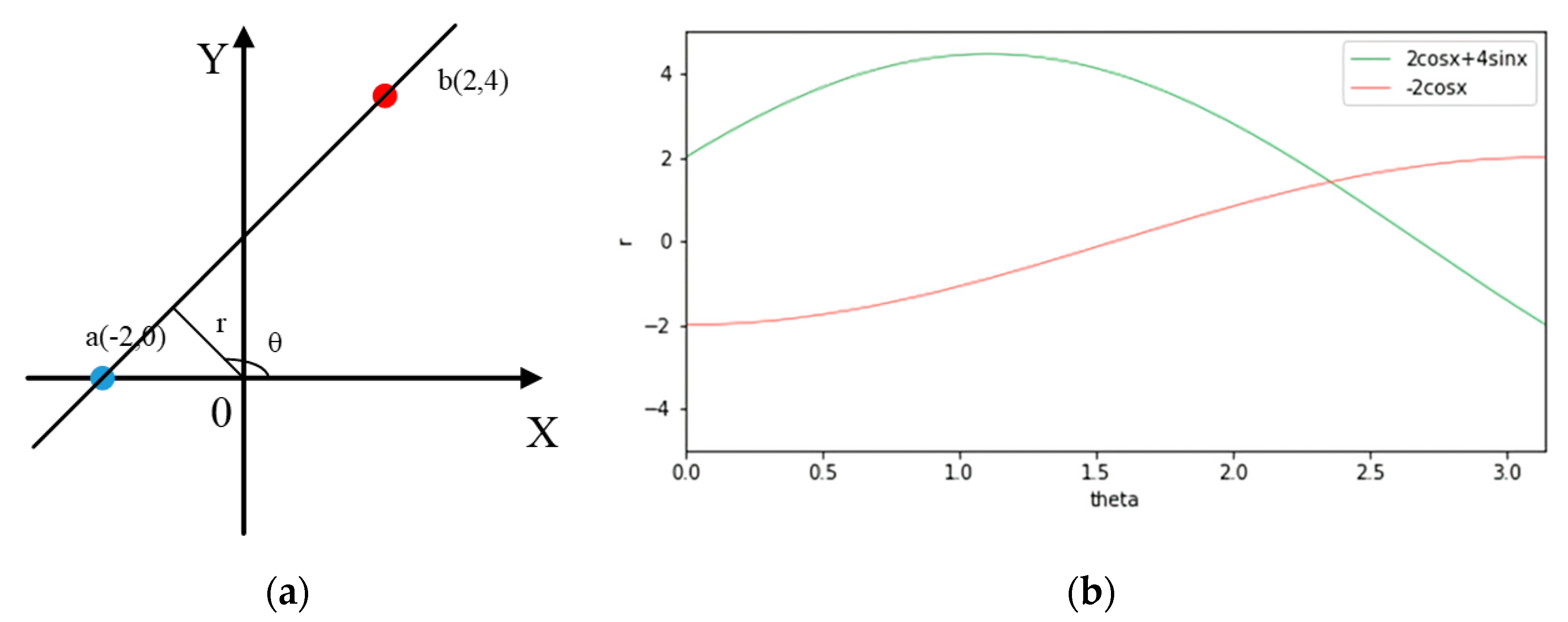
The Hough transform converts the linear detection problems in the image space into cumulative calculations of points in the parameter space according to the mapping relationship. As shown in
Figure 4a, in a slope–intercept form, if the line is perpendicular to the X-axis, and the values of k and b are close to infinity, then the calculation will increase [
22], thus, a polar coordinate equation is used:
, where r is the shortest distance from the origin to the line and the θ is the angle of the normal of line and X-axis. As shown in
Figure 4b, the peak of the line intersection is converted to the peak of the curve intersection in the polar coordinate system.
The borehole log can be divided into two parts from the content: table lines and text. Table lines directly extracted from the Hough transform may be table lines or segments formed by text, so the main problem with table line extraction is filtering out the disruptive lines produced by the text.
The most important feature of the table document is that it is a table composed of a vertical crossline intersection, where the segment must be a straight line rather than a curve. The compression (or other reasons) will cause information loss, so there will be interruptions occasionally between the lines. The break between the table lines can be tolerated, but the break between the text has zero tolerance. When the length of a segment is less than the threshold LINE_GAP, it is not recognized as a table line.
The Hough transform can identify a line at any angle in the image. The most important feature of the table document is the table composed of lines intersecting vertically. The borehole log is derived from the standard format export, with only vertical and horizontal lines. Segments in other directions are mostly formed by text interference, so the linear detection here involves only two angles of 0 and 90 degrees. The identification results are shown in
Figure 5.
4.3. Corner Mark Acquisition
After the table line is extracted, it is divided into n horizontal lines and m vertical lines by angle, and each pair of perpendicular table lines produces an intersection, representing the table line by two endpoints:
where
xr1 <
xr2,
yc1 <
yc2. Every set of segments has a unique intersection (
xc,
yr) and
xc represents the abscissa of the point on the table vertical line, which represents the distance to the left boundary of the rectangular image.
yr represents the ordinates of the point on the table horizontal line, which represents the distance from the top boundary on the rectangular image.
The relationship between the intersection and the corresponding segment group can assign a corner attribute to each intersection. If the intersection is the left endpoint of the table horizontal line and is the top endpoint of the table vertical line, the corner attribute of this point is No.1, the intersection is named No.1 corner, and the relationship function is as follows:
Intersection point can have multiple corner attributes. For example, the point inside a table has a maximum probability of being a compound corner with four corner attributes, and a point at the table boundary may be a compound corner with two corner attributes. The expression of a corner mark is to add an array with a length of four; the value of the array is 0 or 1.
where (
x,
y) stores the coordinates of the corner and the type stores the type of the corner. If there is a corner mark s = {point (50, 100), type [1, 0, 1, 0]}, it represents a compound corner mark located at (50, 100) with two corner attributes of No.1 and No.3.
4.4. Cell Slices Based on Three Corners Combinations
The basic element of a table is a rectangular cell, and the most obvious feature of a cell is four vertices. In a borehole log, a standard cell consists of four corner marks, as shown in
Figure 6a. In a standard table, a pair of corner No.1 and the nearest corner No.4 (from corner No.1) can locate a cell, but the arrangement of cells in the borehole log is not regular, as shown in
Figure 6b; the shadow area is the area that may be misidentified. In order to prevent such errors, a combined triangle (No.1, No.2, No.4) is taken to locate cells. Due to the lack of corner No.3 in the deformed cells, a cell could be located accurately through corner No.1, corner No.2 on the nearest right side of corner No.1, and corner No.4 below corner No.2, as shown in
Figure 6c.
When locating a cell by triangular combination, all the (i, j) satisfying the formula
should be obtained first, where the sign is a two-dimensional array that stores the intersections by rows.
represents corner No.1 which is located in the j column and the i row; after determining k, which makes
, there is no
∈; (j, k) makes
and
is nearest to corner No.2 on the right side of
; after determining l, r, which makes
, there is no l’∈ (i, l), r’∈ N that satisfies
.
is the nearest corner No.4 mark which locates below
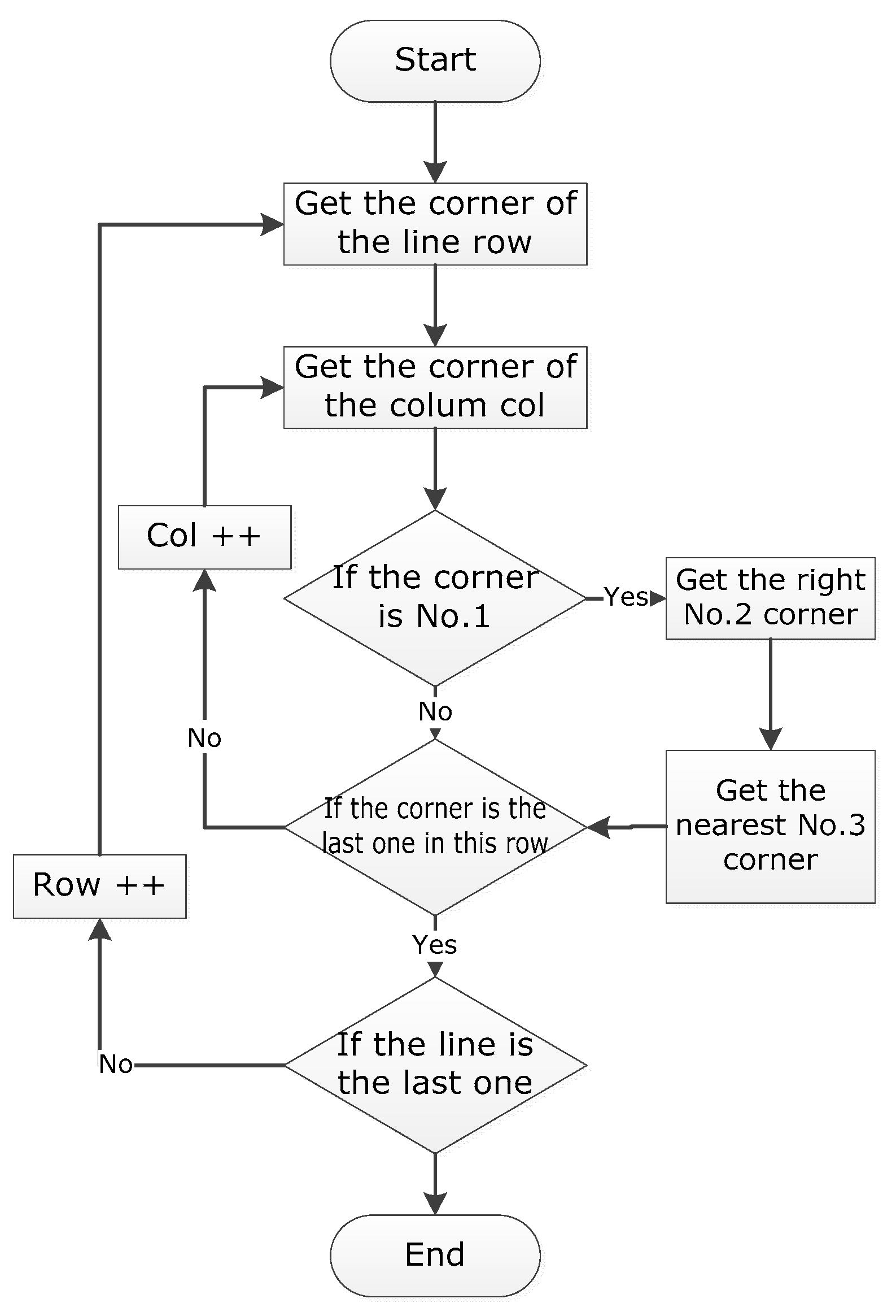
; corresponding cells are obtained by using the obtained combination of corner marks No.1, No.2, and No.4. By using the method of segmenting and judging cells (
Figure 7) row by row, and column by column, serial rectangular cells (
Figure 8) can finally be obtained.
5. Borehole Log Content Recognition Based on Deep Learning and Tesseract
After pre-processing table line recognition and corner extraction, the segmented cells are obtained. The next step is the content extraction of the cell. The contents of the divided borehole log image mainly include characters, numbers and geological symbols. As there are fewer types of numbers, and the frequency of occurrence in the borehole log image is lower, the identification of numbers is relatively easy to achieve. However, due to the large number of professional vocabulary and font types, it is difficult to recognize the characters that occupy a relatively high proportion in the image content [
23]. Furthermore, when it comes to extracting professional geological symbols with an upper and lower label (Q
el) or with a special character (γ
53), low efficiency of the recognition is the primal problem [
24]. Accurate identification of the characters and special geological symbols in the cell is an important step in the identification of the contents of the borehole log.
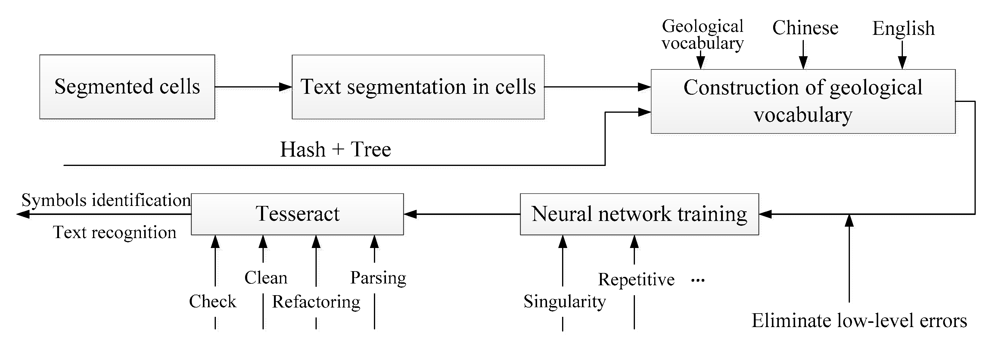
This article uses commonly used Chinese vocabulary and English vocabulary and professional geological survey terms to construct a geological vocabulary, and then uses the LeNet-5 network to carry out printed character recognition training to achieve the extraction of text information in the borehole log. The overall flow of this method is shown in
Figure 9.
5.1. Text Segmentation in Cells
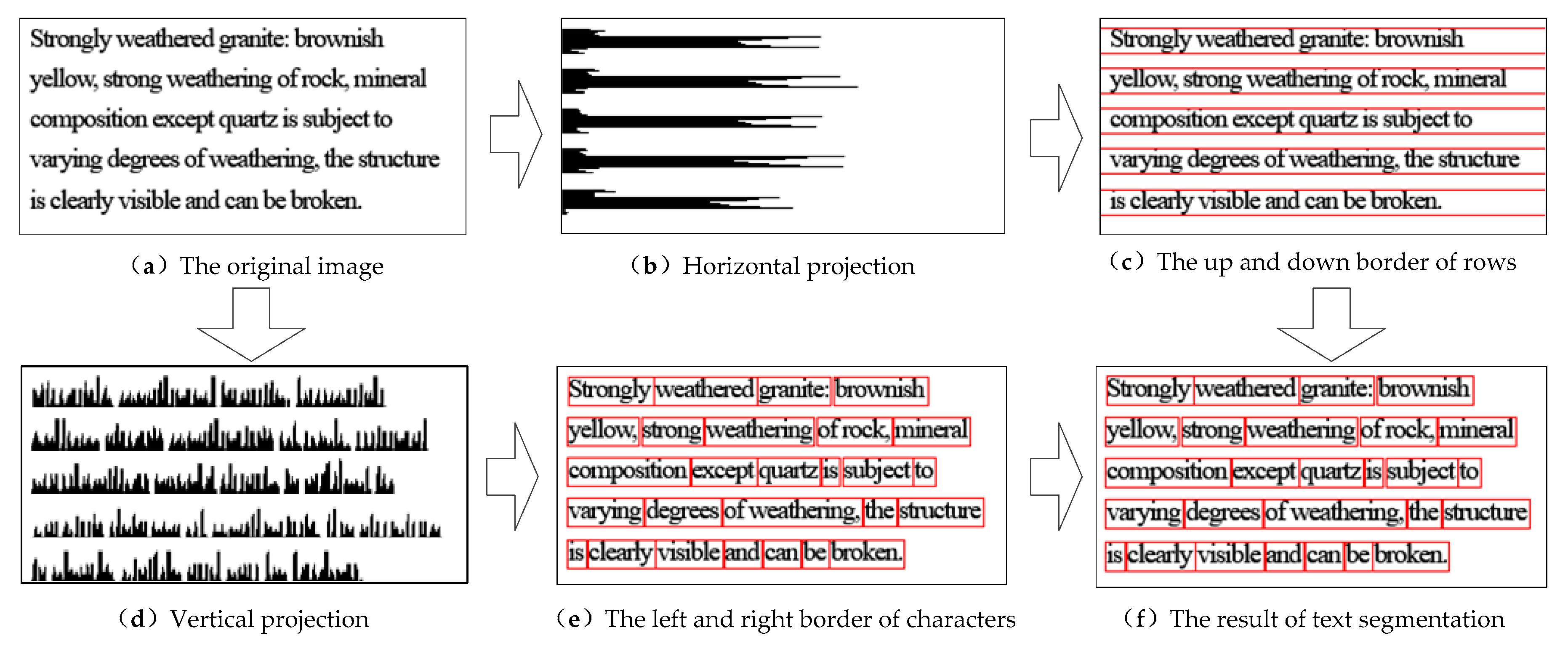
In the previous chapter, the identification of the structure of the borehole histogram was completed, and a series of divided cell images were obtained. Before text recognition, the cell image needs to be segmented at the character level. This process first divides the cell row, then the column, and finally the individual characters(
Figure 10).
The image is grayed and binarized successively, and then scanned from top to bottom, recording the number of 0 values (black pixels) and 255 values (white pixels) that appear in each line, and the pixel values obtained by scanning are accumulated. From the accumulation result, the upper and lower boundaries of each row can be obtained. Then, the borders of each row are used to split the contents of the cell. The same method is used for vertical scanning to obtain a vertical projection spectrum, which realizes the vertical division of each line of text, and then completes the division of multiple lines of text in the cell. The OCR system is used to recognize single characters based on the cell image. The segmented characters will be sent to the next classifier for classification and recognition to obtain more accurate recognition results.
5.2. Constructuction of Geological Vocabulary
The purpose of constructing geological vocabulary is to facilitate the program to find words. The basic data of the lexicon used in this article are selected from multiple vocabularies such as “common geotechnical names”, “geology”, “geological dictionary” in the Sogou input method, etc. The suffix of the Sogou input method’s vocabulary file is scel, the encoding format is Unicode, and the code is written to restore the content of the file to the required string and word array, which is convenient for building the lexicon.
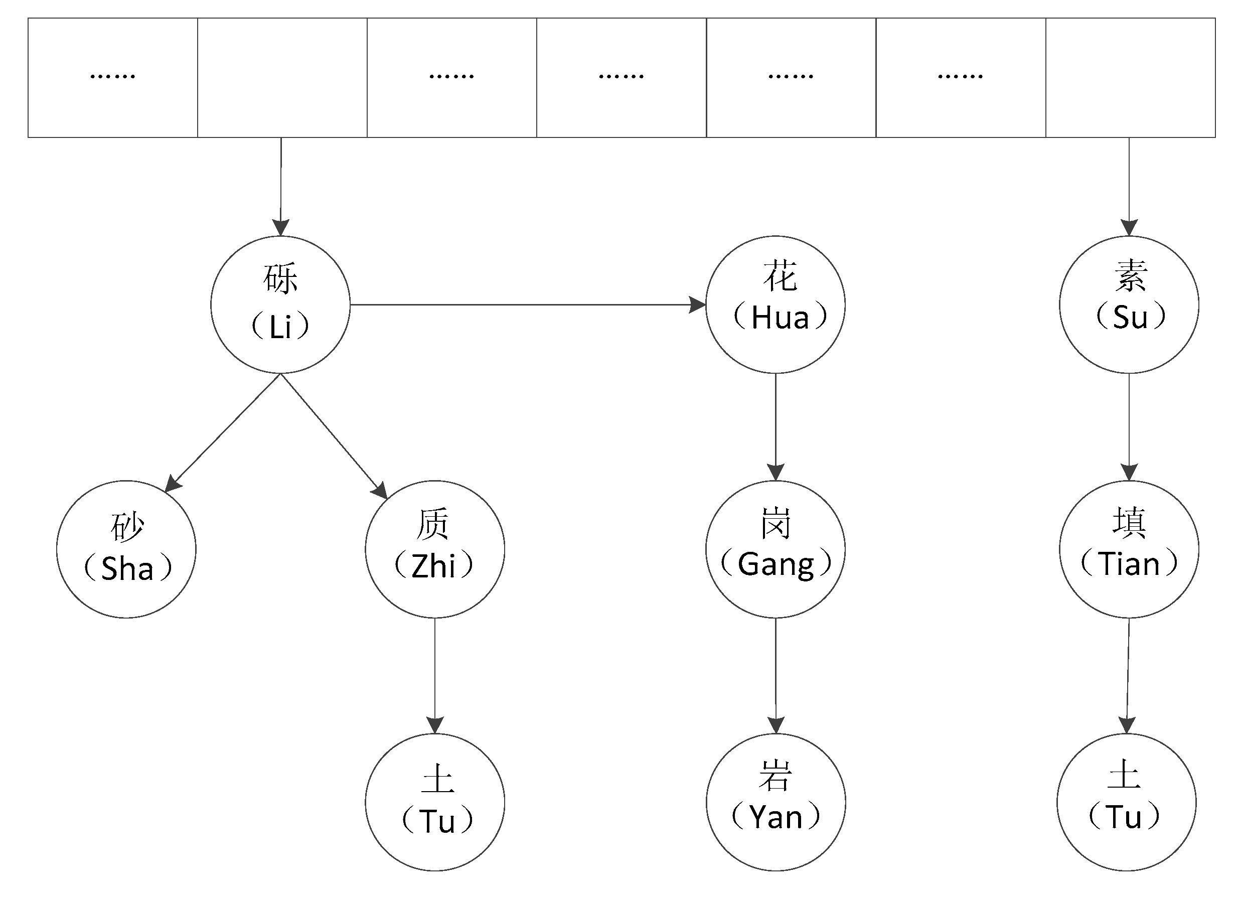
The structure of the database used in this paper is similar to Redis, which uses hash to store data. Redis hash storage is a storage method of significant value, and “hash + tree” is used to construct a geological lexicon. The geological vocabulary is stored in the form of a tree, each word corresponding to a tree-shaped node, and the Chinese characters in the first node are hashed to find the index value. When there are different words that share the same index value, the chain address method is used to resolve the conflict. Different words with the same word appear, share the same node starting with the first node, split at the first different node, and generate a subtree for the node.
For example, the Chinese characters “Hua” and “Li” have the same index value after hash operation, and the chain address method is used to resolve the conflict. The “Li” node derives a node to store “Hua”, because “gravel” and “clay” have the same first node “gravel” and share the first node. As a result, a sub-tree is divided under the “gravel” node to store the subsequent text “clay”(
Figure 11).
5.3. Neural Network Training
CNN has advantages in improving the accuracy of professional vocabulary or sentences composed of multiple words. In this paper, the LeNet-5 network is applied to the training of printed characters recognition. The LeNet-5 network model has seven layers and determines the basic architecture of CNN: the convolution layer, the pooling layer, and the fully connected layer. In this paper, the LeNet-5 network is partially optimized(
Figure 12). At the input layer of the model, the pictures are normalized so that the size of the input images is 64 * 64 pixels. In order to prevent the problem of overfitting of the training model, dropout is added to the fully connected layer, which can improve the performance of the neural network by preventing the joint action of the feature detector when the activation value of a certain neuron stops working with a certain probability p, making the model more generalized.
Dropout can reduce neurons and only add a complicated co-adaptation relationship. Dropout causes two neurons to not appear in a dropout network every time, so that the weight update no longer depends on the joint action of hidden nodes with the fixed relationship, which prevents certain features from being effective only under other specific features, forcing the learning of the network to have more robust features that also exist in random subsets of other neurons.
On this basis, the Tesseract recognition method is adopted to extract the top k characters with the highest recognition similarity for the text recognition results in the picture. By constructing a geological thesaurus as a text recognition context reference, the accuracy of text recognition can be effectively improved.
5.4. Text Identification through Training Sets
Tesseract is an open-source optical character recognition (OCR) engine developed by HP Labs and maintained by Google. Compared to other expensive commercial OCR engines such as Microsoft Office Document Imaging (MODI), Tesseract is more compatible with character recognition in more languages. However, it does not provide a very complete character library for certain languages, so the character library training method is provided, which allows the user to customize their own character library [
25]. After continuous training, the ability to convert images into text is constantly enhanced; it can be used as a template to develop an OCR engine that meets the particular needs of the team [
26].
The description information in the borehole log is mainly the geological terminology of the text format. In order to improve the accuracy of description recognition, the Tesseract-OCR character library is trained by the geological terms in the same batch of borehole logs [
27]. The Tesseract-OCR is imported in order to identify the graph. Before the character library is trained, the recognition rate is higher when the text is simpler for structures, such as “wind” and “chemical” Chinese characters. When the text structure is gradually complicated, the recognition effect gradually deteriorates, and the overall recognition rate is about 20%. After the character library is trained, the recognition of the text part is more accurate, but for punctuation marks such as “,”, and “.”, the recognition effect is poor. The overall recognition rate is 90%, and although it does not achieve a 100% correct rate, it greatly reduces the cost of manual extraction of information.
5.5. Geological Symbol Identification through Training Sets
Because of the uniqueness of geological symbols and their appearance in a random column of the borehole log, training a unique geological symbol library for the column can improve the accuracy of the borehole log text recognition in the most efficient way [
28]. As shown in
Figure 13a, there are columns “ages and genesis” in the primary body, which are simply compared and tested.
Figure 13b is the result of not using the training set, and
Figure 13c shows the recognition effect of the training set obtained by extracting some parts of the geological symbols.
6. Experimental Results
To verify the practicability of the proposed method, 100 borehole logs of the same specification were used to extract information, which was then measured by the efficiency and accuracy of information extraction.
In this paper, the neural network training is realized by using the current mainstream deep learning framework Tensorflow. The specific experimental environment is as follows: Windows10 64-bit system, Python3.5, TensorFlow1.14, Pycharm 2019 Professional 64-bit version, intel core i5 7th generation, GPU 6G GTX1660.
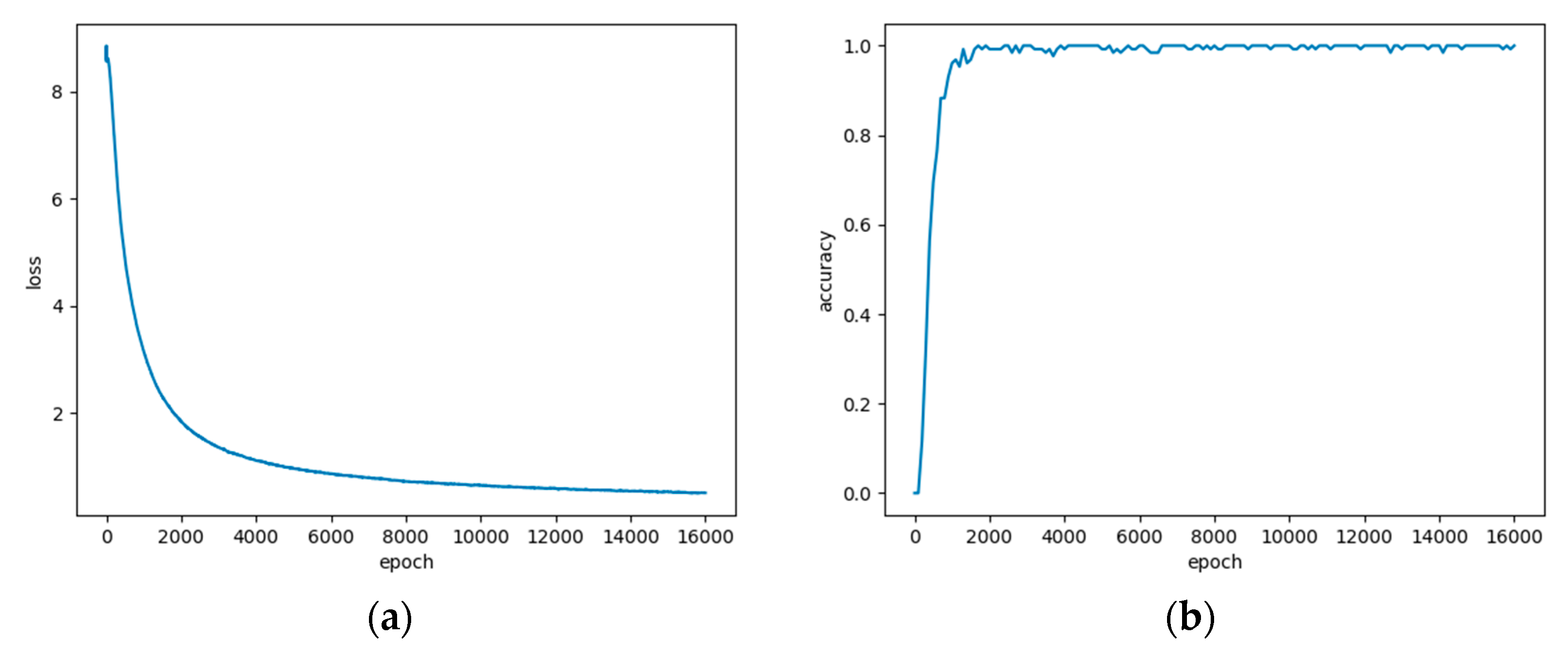
For the test set of this experiment, the recognition accuracy rates of Top1 and Top5 on the network are 99.68% and 99.85%, respectively. Because the characters of the generated dataset are relatively regular and at the same time there is less noise, the recognition accuracy rate for the test set is very high(
Figure 14).
The structural information of this batch of borehole log data is shown in the figure, including basic information, surface structure information, and core stratigraphic description information. If the information is extracted manually, it is necessary to read the borehole log manually and fill the basic information of the borehole, stratum stratification information and other classifications into the structured table. This process can be carried out by an ordinary geological engineer, and generally it takes 30 min for each piece.
With the method proposed in this paper, through the Microsoft Visual C++ programming language, the OpenCV open-source library, and the Tesseract-OCR open-source engine, the automatic extraction system of borehole log information is developed based on the QuantyView platform. QuantyView is a geological information system platform developed by Chin University of Geosciences, consisting of QuantyView2D and QuantyView3D. The QuantyView2D platform integrates two-dimensional graphics and image processing, data management, spatial analysis, and query functions. This paper mainly uses the graph editing function in QuantyView2D. The vectoring borehole log generated by the recognized data is redrawn in QuantyView2D to facilitate data correction.
The operation flow of the borehole log recognition system includes image selection, image preprocessing, table line and corner mark detection, cell positioning, text recognition, text correction, and data storage. Each step can be followed up to see whether it is consistent with the expected results, or one-click generation can be performed after the image selection step to speed up the recognition.
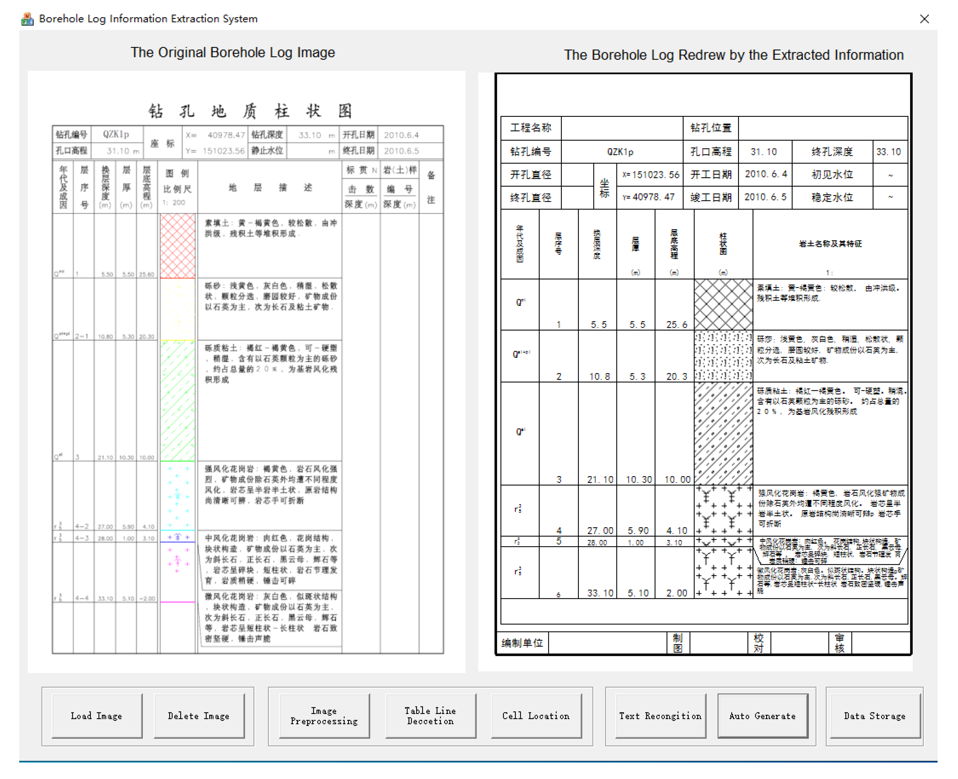
The automatic extraction system of borehole log information has an interface which is divided into three parts. The left side is the source borehole log display area, the middle is the vectoring borehole log display area, and the right side is the functional button area, as shown in
Figure 13. The loaded borehole log image will be displayed in the left part of the software interface, and then the user can click “image preprocessing”, “table line detection” and “cell positioning” (which are the three function buttons). The source borehole log area will display the corresponding recognition results sequentially; the user can click the “text recognition” function button, and the vectoring borehole log area will display the borehole log generated by QuantyView. The recognition results are shown in
Figure 15.
7. Conclusions and Discussion
Extracting information from the borehole log into a structured table for storage and management is a prerequisite for the further use of borehole data. In order to improve the recognition efficiency and accuracy of the borehole log image, this paper mainly solves the following problems:
First, we propose a method based on the three-corner label to identify the structure of the borehole log. By preprocessing the scanned or derived image, the improved line detection algorithm is used to detect all line segments of the table in the image, and the cell positioning algorithm is used to accurately segment cells.
Then, we proposed content recognition based on deep learning and Tesseract. The Tesseract-OCR technology is specifically used to train specific character libraries for specific borehole log text information, which effectively improves the accuracy of geological terminology information text recognition.
Finally, we developed a borehole log information recognition system. In order to verify the identification results more intuitively, we use the recognition result to draw the borehole log in reverse. By doing so, it compares the drawn log with the original log in the same window, which can visually detect the errors in the recognition result and can correct and modify the identified data.
Although the method and software developed in this paper can improve the efficiency of borehole log extraction, there are still many steps for improvement. For example, the existing table recognition algorithm has high recognition accuracy for tables with only horizontal and vertical lines and, as a result, many cells will be missed when there are several slashes. Changing the theta parameter in the Hough transform can solve this problem, but it will increase the number of calculations, which is a waste of computing resources. In addition, there should not be a maximum of four types of corner marks for 90 degrees only, as if there is a diagonal line from the upper left corner to the lower right corner in the cell, the cell will become composed of three corner markers and, thus, the positioning method needs to be improved, requiring better universality.
Experimental results show that the method proposed in this paper can remarkably improve the efficiency of text information extraction from the borehole log. However, the content of the borehole log contains not only text, but also graphs in the form of curves, polylines, and core photos. Therefore, in future research, we will study how information in multiple formats can be automatically extracted.

