Article

NESO-Based Path Following Control for Underactuated Hovercrafts with Unknown Nonlinear Uncertainties and a Safety Limit Constraint

1
College of Automation, Harbin Engineering University, Harbin 150001, China
2
Department of Biomedical Engineering, National University of Singapore, Singapore 119077, Singapore
*
Author to whom correspondence should be addressed.
Appl. Sci. 2020, 10(15), 5287; https://doi.org/10.3390/app10155287
Submission received: 28 June 2020 / Revised: 23 July 2020 / Accepted: 28 July 2020 / Published: 30 July 2020
(This article belongs to the Section Marine Science and Engineering)

Abstract

:

Featured Application

The designed control strategy in this paper is also suitable for the safe control application of other underactuated marine surface vehicles, improving the safety and maneuverability of underactuated marine surface vehicles.

Abstract

In this brief, the path following control problem of underactuated hovercrafts subject to nonlinear time-varying uncertainties and a safety limit constraint (SLC) is addressed. A novel homogenous nonlinear extended state observer (NESO)-based safe motion controller for a path following control scenario of underactuated hovercrafts is proposed. First, a NESO is constructed to estimate and compensate the nonlinear time-varying uncertainties for the underactuated hovercraft. Then, a NESO-based backstepping sliding mode control (BSMC) law with a turning SLC is proposed to achieve the yaw control for underactuated hovercrafts, which improves both safety and maneuverability of the underactuated hovercraft during the path following control scenario. The nonlinear time-varying turning SLC is first directly taken into the control system design, which is achieved by introducing an auxiliary dynamic system to limit the virtual input control during the backstepping design process. A NESO-based backstepping surge control law is also designed to achieve the surge control for underactuated hovercrafts. Furthermore, all error signals of the proposed closed-loop control system are proven to be bounded. Finally, an application case is tested on an underactuated hovercraft to illustrate the effectiveness and superiority of the designed control scheme.

1. Introduction

Nonlinear motion control of marine surface vehicles, which includes underactuated hovercrafts, unmanned surface vehicles, and unmanned underwater vehicles, has attracted the attention of many researchers [1]. Compared with motion control of fully actuated marine surface vehicles, it presents challenging control problems. Hovercrafts, different from the traditional surface marine vehicles, are characterized by underactuated, high velocity and a large size [2]. As shown in Figure 1a, an underactuated hovercraft is supported by a pressurized air cushion, which makes the hard structure just far from the water surface, reducing the water drag, surface interference, and wave-making [3]. This makes it able to withstand motion on different surfaces. Therefore, underactuated hovercrafts are widely used in military and civil fields, such as delivery of landing soldiers, mine clearance, and rescue [4]. Although the underactuated hovercraft has the above advantages, its maneuverability and safety are poor due to its special cushion physical structure. In addition, hovercrafts are usually underactuated, which brings a challenging nonlinear motion automatic control problem [5].
The kinetics of underactuated hovercrafts is a complex nonlinear system, and it is very difficult to obtain an accurate model of underactuated hovercrafts for the control system design [6]. In addition, underactuated hovercrafts are suffering from the complex external ocean disturbances during navigation, thus there are assorted uncertainties, such as external disturbances, unmodeled hydrodynamics, and parametric perturbations present in an underactuated hovercraft motion model [7]. Therefore, control of underactuated hovercrafts faces challenges due to the external ocean disturbances and internal unmodeled dynamics, which has drawn considerable attention from researchers. In recent years, a lot of research, such as fuzzy logic [8] and neural network [9], has been done. However, these methods rely too much on prior knowledge, which makes their implementation more complicated in practice. The extended state observer (ESO), initially proposed by Han in 1988, provides the possibility to overcome the difficulty of control of uncertain systems [10]. ESOs are designed to approximate the unknown “total uncertainties”, which introduce excellent challenges to design a motion controller for marine vehicles that usually has nonlinear uncertainties. The ESO does not rely on any model information so that the fully model-free control for the nonlinear systems with unknown uncertainties are achieved by Huang in [11]. In the past three decades, many studies on ESOs have been carried out [12,13]. The linear extended state observers (LESOs) were designed to estimate the states and the general external disturbances for the autonomous underwater vehicles and unmanned surface vehicles, respectively, by Peng in [14] and Gu in [15]. Although both LESOs and nonlinear extended state observers (NESOs) can estimate the uncertainties, the accuracy of the NESO is better than that of the LESO [14,16]. To estimate the fast-varying disturbances, a harmonic ESO was proposed to achieve a high-accuracy estimation of disturbances for a fully-actuated autonomous underwater vehicle by Lamraoui in [17], where the designed harmonic ESO can only estimate the periodic disturbances. However, for the underactuated hovercraft suffering from unmodeled hydrodynamics and complex oceanic disturbances, the total uncertainties are usually time-varying, which cannot be estimated above ESOs. To approximate the unknown time-varying uncertainties of underactuated hovercrafts, a novel homogenous nonlinear extended state observer (NESO) is first proposed for the underactuated hovercraft to estimate and compensate the unknown time-varying uncertainties in this paper.
To improve the maneuverability of underactuated hovercrafts, various control research has been done, such as the backstepping control [18], the fuzzy control [19], the output feedback control [20], the sliding mode control [21,22], and the robust control [23,24]. Although there are many studies on the control methods of the underactuated hovercraft and better control performances have been achieved, the safety limit has not been taken into account in the above research. To improve the safety of underactuated hovercrafts, the safety limit constraint (SLC) was considered in controller design by [25,26]. A safety-guaranteed auxiliary dynamic system was designed to improve the safety and maneuverability of underactuated hovercrafts by Fu in [25], where the yaw controller with the safety limit was designed by control input constraint. However, the turning limit constraint is indirectly realized by restricting the control input. Thus, the safety parameter cannot be precisely limited to the safety limit. Then, a position-constrained line-of-sight (LOS) guidance algorithm and a barrier Lyapunov function-based yaw velocity controller was proposed by Fu in [26] to achieve the safe control for hovercrafts with the SLC, in which the safety limit parameters were directly considered in controller design. However, the nonlinear time-varying safety limit is not taken into account in [26], and it is also too complicated in practice.
Inspired by the above-mentioned studies, and to deal with nonlinear time-varying uncertainties and SLC problems, a novel safety control strategy for the path following task of underactuated hovercrafts suffering from the nonlinear time-varying turning SLC and the uncertainties is presented in this paper. The main contributions of the proposed safety control strategy include:
  • A homogenous nonlinear extended state observer is first proposed to approximate the nonlinear time-varying uncertainties of underactuated hovercrafts, which will greatly improve the accuracy and performance of the designed control system.
  • The nonlinear time-varying turning safety limit constraint of underactuated hovercrafts is first considered in yaw controller design by introducing an auxiliary variable to limit the virtual control input.
  • The NESO-based backstepping sliding mode control law are initially designed to achieve the dynamic control of path following for underactuated hovercrafts subject to nonlinear time-varying SLC and uncertainties.
The rest of this paper is organized as follows: The preliminaries and problems are introduced in Section 2. Section 3 elaborates the control design, including the NESO and the NESO-based disturbances rejection safe control law with SLC, as well as the stability analysis. The illustrated application case study is presented in Section 4, and the conclusions are given in Section 5 finally.

2. Preliminaries and Problem Formulation

2.1. Preliminaries

In this subsection, some definitions and lemmas are presented to facilitate the analysis and design of control strategies for underactuated hovercrafts.
Definition 1.
(Definition 2.1 in [12]) A function V : n is called homogeneous of degree γ with respect to weight α i > 0 ( i = 1 , , n ) such that
V ( χ α 1 x 1 , χ α 2 x 2 , , χ α n x n ) = χ γ V ( x 1 , x 2 , , x n )
for χ > 0 and all ( x 1 , x 2 , , x n ) n .
Remark 1.
If the function V is differentiable with respect to x n and satisfies Definition 1, then the partial derivative of V respect to x n such that
χ α n x n V ( χ α 1 x 1 , χ α 2 x 2 , , χ α n x n ) = χ γ x n V ( x 1 , x 2 , , x n )
Definition 2.
(Definition 2.1 in [12]) A vector field G : n n is said to be homogeneous of degree γ with respect to weight α i > 0 ( i = 1 , , n ) such that
G i ( χ α 1 x 1 , χ α 2 x 2 , , χ α n x n ) = χ γ + α i G i ( x 1 , x 2 , , x n )
for all ( x 1 , x 2 , , x n ) n and χ > 0 , where G i represents the i -th component of G .
Lemma 1.
(Theorem 2 in [27]) If f is a homogeneous function satisfies f C ( n , n ) , initial state f ( 0 ) = 0 and the equilibrium point x = 0 of system x ˙ = f ( x ) is locally asymptotically stable. Let k be a real number and p be a positive integer such that k > p max { α i ( i = 1 , 2 , , n ) } , then there exists a function V : n such that (1) V C p ( n , ) C ( \ { 0 } , ) , (2) V ( 0 ) = 0 , V ( x ) > 0 for all x 0 and V ( x ) + as x + , (3) V is homogeneous, (4) V ( x ) f ( x ) < 0 , for x 0 .
Lemma 2.
(Lemma 4.2 in [28]) Let V ( x ) and W ( x ) be continuous real-valued function on n and homogeneous with respect to γ of degree h 1 > 0 and h 2 > 0 , respectively, and V is positive definite. Then, for every x n such that
min { W ( s ) } | s : W ( s ) = 1 [ V ( x ) ] h 2 h 1 W ( x ) max { W ( s ) } | s : W ( s ) = 1 [ V ( x ) ] h 2 h 1
Lemma 3.
(Lemma 4.2 in [29]) Let the system x ˙ = f ( x ) and the equilibrium point x = 0 , a continuous positive, radially unbounded function V : n such that V ˙ ( x ) < 0 , x 0 , then the equilibrium point x = 0 is globally asymptotically stable.

2.2. Problem Formulation

In this subsection, the nonlinear dynamics model in the horizontal plane and integer line-of-sight (ILOS) guidance law are described to formulate the motion control problem of path following for underactuated hovercrafts with SLC and uncertainties.

2.2.1. Nonlinear Hovercraft Dynamics with Uncertainties and SLC

To describe the motion of an underactuated hovercraft in horizontal plan, we define the inertial north-east-down (NED) reference frame and the body-fixed (BF) reference frame as shown in Figure 1b. Then, a mathematical motion model of three-degree-of-freedom (including surge, sway, and yaw) for underactuated hovercrafts is established as follows.
The three-degree-of-freedom kinematics equations of an underactuated hovercraft can be written as [30]
{ x ˙ = u cos ψ v sin ψ y ˙ = u sin ψ + v cos ψ ψ ˙ = r
where x , y , and ψ denote the north, east positions and heading attitude of an underactuated hovercraft in the inertial NED frame, respectively. u , v , and r denote the surge linear velocity, sway linear velocity, and yaw angular velocity in the BF frame for an underactuated hovercraft, respectively.
The three-degree-of-freedom kinetic equations of an underactuated hovercraft with turning SLC can be expressed as [31]
{ m ( u ˙ v r ) = F x a + F x h + F x m + F x P m ( v ˙ + u r ) = F y a + F y h + F y m + F y c I z r ˙ = M z a + M z h + M z m + M z c + M z R
subject to
r l min ( t ) r r l max ( t )
in which m represent the mass and I z is the rotational inertia of an underactuated hovercraft. F x a , F y a , and M z a represent the aerodynamic forces and moment. F x h , F y h , and M z h are the hydrodynamic forces and moment. F x m , F y m , and M z m denote the air momentum forces and moment. F y c and M z c denote the cushion force and moment. F x P is the propulsion force of the aerial propeller that should be designed to achieve the yaw control, and M z R is the force of the rudder to be designed later for controlling the surge motion of an underactuated hovercraft. All above forces and moments have their own complex nonlinear mathematical models, and because the focus of this paper is the design of the control strategy and considering the limitations of the length of the paper, the details of the model are not expanded. The details can be referred to the specific modeling description in the literature [4]. r l max ( t ) and r l min ( t ) represent the maximum and minimum of the turning safety limit (control area) parameters shown in Figure 2a, respectively.
Remark 2.
The safety limit, including tuning velocity, roll angle, and sideslip angle three parameters, is a series of most essential constraint indicators to ensure the safety of an underactuated hovercraft. The change of turning velocity directly affects the change of sideslip angle. Thus, the indirect control of the sideslip angle can be realized by controlling the turning velocity. Additionally, the roll angle is affected by the cushion system, which is not included here. Therefore, this paper addresses a more safe control strategy of underactuated hovercrafts subject to the turning SLC.
The turning safety limit of an underactuated hovercraft is shown in Figure 2a, which is divided into three parts: safety area, alert area, and control area. When the turning velocity belongs to the alert area, the underactuated hovercraft will alert the sailor. The limit of the control area is the allowable maximum turning rate. Note that the turning safety limit of an underactuated hovercraft is a nonlinear function with respect to velocity, thus it is time-varying.
To facilitate the NESO design, define the total uncertainties as
{ d u ( t ) = : f u ( t , u , v , r , τ w u ) = ( F x a + F x h + F x m ) / m + v r d v ( t ) = : f v ( t , u , v , r , τ w v ) = ( F y a + F y h + F y m + F y c ) / m u r d r ( t ) = : f r ( t , u , v , r , τ w r ) = ( M z a + M z h + M z c + M z m ) / I z
M = d i a g { m , m , I z } 3 , τ = [ F x P , 0 , M z R ] T 3 , η = [ x , y , ψ ] T 3 , υ = [ u , v , r ] T 3 , and the extended state vector d = [ d u , d v , d r ] T 3 , then the motion equations of underactuated hovercrafts can be expressed as
{ η ˙ = R ( ψ ) υ υ ˙ = d + M 1 τ
where the rotate matrix R ( ψ ) 3 × 3 is defined as
R ( ψ ) = [ cos ψ sin ψ 0 sin ψ cos ψ 0 0 0 1 ]
Remark 3.
The hydrodynamic force, the aerodynamic force, as well as the air momentum force in the kinetic model (6), are the time-varying uncertainties arising from the external environmental disturbances arising from wind, waves, and currents. The internal model uncertainties caused by unmodeled hydrodynamic terms are also unknown in practice. Therefore, the total uncertainties vector d , which should be approximated by the positions and heading measurement from GPS, is totally unknown.

2.2.2. LOS Guidance Law for Underactuated Hovercrafts

The Serret–Frenet (SF) reference frame, composed of tangent and normal vectors of the path reference point, is introduced to describe line-of-sight (LOS) of the path following problems. The geometric schematic diagram of LOS guidance law of an underactuated hovercraft is illustrated in Figure 1b, where the γ ( ϖ ) = atan 2 ( y d ( ϖ ) , x d ( ϖ ) ) such that x d ( ϖ ) = x d / ϖ , y d ( ϖ ) = y d / ϖ , is used to rotate the NED frame to the SF frame. P d n represents the reference position. For any reference path point P d n , it can be parameterized as P d n = ( x d ( ϖ ) , y d ( ϖ ) ) by the independent path continuous scalar variable ϖ .
Then, for an underactuated hovercraft located at P n = ( x , y ) , by rotating the inertial NED frame to the SF frame, the along-tracking error x e and cross-tracking error y e between P n and P d n in the SF frame can be obtained as
[ x e y e ] = [ cos ( γ ( ϖ ) ) sin ( γ ( ϖ ) ) sin ( γ ( ϖ ) ) cos ( γ ( ϖ ) ) ] T S T ( γ ) [ x x d y y d ]
where S T ( γ ) 2 × 2 represents the rotation matrix.
Taking the derivative of (11) for (9), the tracking error dynamics can be obtained as
{ x ˙ e = u cos ( ψ γ ( ϖ ) ) v sin ( ψ γ ( ϖ ) ) + γ ˙ y e u x e y ˙ e = u sin ( ψ γ ( ϖ ) ) + v cos ( ψ γ ( ϖ ) ) γ ˙ x e
where u x e is the virtual surge velocity of the reference point that can be expressed as
u x e = ϖ ˙ x d 2 ( ϖ ) + y d 2 ( ϖ )
that stabilizes the along-tracking error x e .
Both the cross-tracking error y e and the path tangential angle γ ( ϖ ) are available, thus the desired heading angle is selected as [32]
{ ψ I L O S = γ ( ϖ ) atan ( y e + ς π I L O S Δ t ) π ˙ I L O S = y e Δ t ( y e + ς π I L O S ) 2 + Δ t 2
where ς > 0 is the designed parameter of the ILOS (14), and Δ t denotes the time-varying look-ahead distance proposed in [33] that can be expressed as
Δ t = ( Δ max Δ min ) exp ( γ Δ | y e | ) + Δ min
in which γ Δ > 0 is the convergence rate, and Δ min and Δ max represent the upper and lower bounds of Δ t , respectively.
The control objective is designing a disturbances rejection safe control strategy with SLC to achieve better control performance for underactuated hovercrafts that suffer from the nonlinear time-varying SLC and unknown nonlinear time-varying uncertainties.
To realize the above control objective, some assumptions need to be made as follows.
Assumption 1.
The positions and velocities of underactuated hovercrafts are available.
Assumption 2.
The total uncertainties functions d = [ f u ( u , v , r , τ w u ) , f v ( u , v , r , τ w v ) , f r ( u , v , r , τ w r ) ] T are bounded and differentiable such that d B 1 = [ 11 , 12 , 13 ] T and d ˙ ( t ) B 2 = [ 21 , 22 , 23 ] T , where i j ( i = 1 , 2 ; j = 1 , 2 , 3 ) are some positive constants.

3. Control Strategy Design

In this section, a novel NESO is proposed to approximate and compensate the unknown total nonlinear time-varying uncertainties of an underactuated hovercraft at first. Then, the safe control law with SLC is proposed to achieve the improvement of the safety of underactuated hovercrafts with the unknown total nonlinear time-varying uncertainties. Finally, the stability of the proposed closed-loop safe control system is analyzed.

3.1. The NESO for Hovercrafts Subject to Unknown Nonlinear Time-Varying Uncertainties

In this subsection, the total uncertainties including the unknown internal unmodeled dynamics and the unknown external ocean disturbances are needed to be estimated.
For the nonlinear system (9) with unknown nonlinear time-varying uncertainties, a homogenous nonlinear extended state observer is constructed as
{ η ^ ˙ = R ( ψ ) υ ^ β 1 R ( ψ ) [ R T ( ψ ) ( η ^ η ) ] α υ ^ ˙ = d ^ β 2 [ R T ( ψ ) ( η ^ η ) ] 2 α 1 + M 1 τ d ^ ˙ = β 3 [ R T ( ψ ) ( η ^ η ) ] 3 α 2 ,
where [ x ] α = [ s i g n ( x 1 ) | x 1 | α ,   s i g n ( x 2 ) | x 2 | α ,   s i g n ( x 3 ) | x 3 | α ] T 3 , x = [ x 1 , x 2 , x 3 ] T 3 , α ( 2 / 3 , 1 ) , β i ( i = 1 , 2 , 3 ) are the designed positive parameters, and η ^ = [ x ^ , y ^ , ψ ^ ] T 3 , υ ^ = [ u ^ , v ^ , r ^ ] T 3 , d ^ = [ d ^ u , d ^ v , d ^ r ] T 3 with x ^ , y ^ , ψ ^ , u ^ , v ^ , r ^ , d ^ u , d ^ v , and d ^ r are the estimations of x , y , ψ , u , v , r , d u , d v and d r , respectively.
Denoting the estimation error vectors as
{ η ˜ = η ^ η υ ˜ = υ ^ υ d ˜ = d ^ d
and
{ E 1 ( t ) = R T ( ψ ) η ˜ ( t ) E 2 ( t ) = υ ˜ ( t ) E 3 ( t ) = d ˜ ( t )
then, it is follows (17) and (18) that the error dynamics of the NESO can be described as
{ E ˙ 1 ( t ) = E 2 ( t ) β 1 [ E 1 ] α E ˙ 2 ( t ) = E 3 ( t ) β 2 [ E 1 ] 2 α 1 E ˙ 3 ( t ) = β 3 [ E 1 ] 3 α 2 d ˙ ( t )
To facilitate stability analysis of observer error dynamics (19), define observer error vector E o = [ E 1 T , E 2 T , E 3 T ] T 9 , then the observer error dynamics can be rewritten as
E ˙ o = F ( E o ) + B d ˙ ( t )
where F ( E o ) = [ β 1 [ E 1 ( t ) ] α + E 2 ( t ) , β 2 [ E 1 ( t ) ] 2 α 1 + E 3 ( t ) , β 3 [ Ε 1 ( t ) ] 3 α 2 ] T 9 and B = [ 0 3 × 3 , 0 3 × 3 , I 3 × 3 ] T 9 × 3 .
Theorem 1.
Consider Assumption 1 and Assumption 2, the homogenous nonlinear extended state observer (16), nonlinear system (9) with the unknown nonlinear time-varying uncertainties, the estimation error dynamic (20) is convergent for any initial values η ( 0 ) , υ ( 0 ) , η ^ ( 0 ) , υ ^ ( 0 ) and the bounded total uncertainties d ( t )
Proof. 
It follows Definition 2 that the vector field F(Eo) is homogenous of degree α−1 with respect to weights {1,α,2α−1}, then it follows Lemma 1 that there exists a positive definite radial unbounded function V o ( E o ) : 9 satisfying that V o ( E o ) is homogeneous of degree γ in weights { 1 , α , 2 α 1 } , and E 1   V o ( E o ) ( E 2 ( t ) β 1 [ E 1 ] α ) + E 2   V o ( E o ) ( E 3 ( t ) β 2 [ E 1 ] 2 α 1 ) + E 3   V o ( E o ) ( β 3 [ E 1 ] 3 α 2 ) is homogeneous of degree γ + α 1 and negative definite.
Then, there exists those positive constants c i ( i = 1 , , 4 ) > 0 according to Lemma 2 such that
c 1 V o ( E o ) γ + α 1 γ E 1   V o ( E o ) ( E 2 ( t ) β 1 [ E 1 ] α ) + E 2   V o ( E o ) ( E 3 ( t ) β 2 [ E 1 ] 2 α 1 ) + E 3   V o ( E o ) ( β 3 [ E 1 ] 3 α 2 ) c 2 V o ( E o ) γ + α 1 γ
and
| E 3   V o ( E o ) | c 3 V o ( E o ) γ 2 α + 1 γ
Next, taking the time derivative of V o ( E o ) , we have
V ˙ o ( E o ) = E 1   V o ( E o ) ( E 2 ( t ) β 1 [ E 1 ] α ) + E 2   V o ( E o ) ( E 3 ( t ) β 2 [ E 1 ] 2 α 1 ) + E 3   V o ( E o ) ( β 3 [ E 1 ] 3 α 2 ) + E 3   V o ( E o ) d ˙ ( t ) c 2 V o ( E o ) γ + α 1 γ + | E 3   V o ( E o ) | d ˙ ( t )
Let Q ( E o ) = c 4 V o ( E o ) γ + α 1 γ . Since V o ( E o ) is a radially unbounded and positive definite function, thus that { E o | V o ( E o ) d 0 } for any d 0 > 0 is bounded and lim E o V ( E o ) . It follows (22) and α ( 2 / 3 , 1 ) that lim E o Q ( E o ) / |   V o ( E o ) / E 3 | . Thus, there exists a positive constant 3 such that | V o ( E o ) / E 3 | Q ( E o ) for all E 3 , yields
V ˙ o ( E o ) c 2 V o ( E o ) γ + α 1 γ + c 4 V o ( E o ) γ + α 1 γ d ˙ ( t ) = ( c 2 c 4 d ˙ ( t ) ) V o ( E o ) γ + α 1 γ κ V o ( E o ) γ + α 1 γ 0
where κ = c 2 c 4 2 > 0 . Thus, all observer signals of the NESO are globally asymptotically stable for the bounded total uncertainties by Lemma 3, that is, there exists positive parameters b u , b v , b r b d u b d v and b d r such that
υ ˜ [ b u , b v , b r ] T
d ˜ [ b d u , b d v , b d r ] T
then, the Theorem 1 has been proven. □
Remark 4.
Note that the unknown nonlinear time-varying uncertainties can be approximated by fuzzy logic [34] or neural networks [9]. However, the algorithm will be more complex in practice. Compared with the fuzzy logic or neural network, the NESO has the following advantages: 1) The NESO can approximate the uncertainties without any prior knowledge and the precise mathematical model. 2) The NESO does not need data training like fuzzy logic or a neural network, greatly reducing the computation time, and realizing the real-time control for the underactuated hovercraft. The designed NESO can approximate the total uncertainties induced by the internal unmodeled dynamics and the external nonlinear time-varying ocean disturbances, which will greatly simplify the design and achieve a better performance of the control system.
The advantages of the proposed NESO for an underactuated hovercraft can be summarized as follows.
  • First, the uncertainties can be approximated simultaneously via the position-heading of the underactuated hovercraft from the GPS.
  • Second, the proposed homogenous NESO does not rely on the model parameter information, and the design of the NESO is independent of the control system.
  • Third, the proposed NESO has better approximate performance—more accuracy and better transience than the LESO.
  • Moreover, the proposed NESO can compensate the unknown nonlinear time-varying total uncertainties of underactuated hovercrafts in the control system design, which will greatly improve the accuracy and performance of the designed control system.

3.2. Safety Control Strategy for the Underactuated Hovercraft

In this subsection, a novel NESO-based backstepping sliding mode yaw control law with turning SLC is presented to achieve the control for an underactuated hovercraft with nonlinear time-varying turning SLC, and a disturbances rejection surge controller is designed using the NESO.

3.2.1. Yaw Safe Control Law for the Underactuated Hovercraft

A novel NESO-based backstepping sliding mode controller with turning SLC is achieved by adopting an auxiliary variable during the virtual law of the backstepping control to achieve yaw control for an underactuated hovercraft.
Step 1: Define the heading and yaw tracking errors as ψ e = ψ ψ d , r e = r α r , then it follows from (9) that the dynamic of the heading and yaw tracking errors can be expressed as
ψ ˙ e = r ψ ˙ d
r ˙ e = r ˙ α ˙ r
To stabilize the heading-tracking error of (27) and take the nonlinear time-varying turning SLC into account, a virtual control α r with an auxiliary variable is designed as
α r = Δ α r + α r c
α r c = k ψ ψ e + ψ ˙ d + k ζ ζ
where k ψ and k ζ are control parameters to be designed, and the ζ is an auxiliary variable updated by
ζ ˙ = { k a ζ | Δ α r ψ e | + 1 2 Δ α r 2 ζ 2 ζ + Δ α r , | ζ | 0 , | ζ | <
where is a small positive parameter, k a > 0 is a designed parameter, and the virtual control law α r is limited by the turning safety limit
α r = { r l max ( t ) α r c r lmax ( t ) α r c r lmin ( t ) α r c < r lmax ( t ) r l min ( t ) α r c < r lmin ( t )
where r l max ( t ) and r l min ( t ) represent the maximum and minimum of the turning safety limit (control area) parameter shown in Figure 2a, respectively.
Remark 5.
As a typical high-performance marine surface vehicle, underactuated hovercrafts generally sail at high speed, and its safety limit is an important performance index to ensure its safe navigation. Therefore, the constraint of the safety limit needs to be considered in the control law design process of underactuated hovercrafts. Considering the SLC, the virtual control law is limited by introducing an auxiliary dynamic variable. Finally, the safe control is realized by tracking the virtual control law.
Consider the candidate Lyapunov function V 1 = ( ψ e 2 + ζ 2 ) / 2 , together with (27) and (31), the derivative of V 1 can be obtained as
V ˙ 1 = ψ e ψ ˙ e + ζ ζ ˙ = ψ e ( r e + α r ψ ˙ d ) + ζ ( k a ζ | Δ α r ψ e | + Δ α r 2 / 2 ζ 2 ζ + Δ α r )
It follows (29) that
V ˙ 1 = ψ e ( r e k ψ ψ e + ψ ˙ d + k ζ ζ + Δ α r ψ ˙ d ) k a ζ 2 | Δ α r ψ e | 1 2 Δ α r 2 + Δ α r ζ = k ψ ψ e 2 + k ζ ψ e ζ + ψ e r e + Δ α r ψ e k a ζ 2 | Δ α r ψ e | 1 2 Δ α r 2 + Δ α r ζ
Using Young’s inequalities k ζ ψ e ζ k ζ ψ e 2 / 2 ε 1 + ε 1 k ζ ζ 2 / 2 , ψ e r e ψ e 2 / 2 + r e 2 / 2 , and Δ α r ζ Δ α r 2 / 2 + ζ 2 / 2 , where ε 1 is a positive constant, then we have that
V ˙ 1 = k ψ ψ e 2 + k ζ 2 ε 1 ψ e 2 + ε 1 k ζ 2 ζ 2 + 1 2 ψ e 2 + 1 2 r e 2 + Δ α r ψ e k a ζ 2 | Δ α r ψ e | + 1 2 ζ 2 = ( k ψ k ζ 2 ε 1 1 2 ) ψ e 2 ( k a ε 1 k ζ 2 1 2 ) + 1 2 r e 2 + Δ α r ψ e | Δ α r ψ e | ( k ψ k ζ 2 ε 1 1 2 ) ψ e 2 ( k a ε 1 k ζ 2 1 2 ) + 1 2 r e 2
To further improve the maneuverability of designed control system, the proposed NESO and backstepping sliding mode control technologies are applied to design a disturbances rejection control law with SLC for an underactuated hovercraft as follows.
Step 2: Define the sliding mode surface:
s = k s ψ e + r e
where k s is a designed positive constant, then considering the following Lyapunov function V r = V 1 + s 2 / 2 , and differentiating V r respect to time, yields
V ˙ r = V ˙ 1 + s s ˙ = V ˙ 1 + s ( k s ψ ˙ e + r ˙ e ) = V ˙ 1 + s ( k s ψ ˙ e + r ˙ α ˙ r ) ( k ψ k ζ 2 ε 1 1 2 ) ψ e 2 ( k a ε 1 k ζ 2 1 2 ) ζ 2 + 1 2 r e 2 + s ( k s ( r e k ψ ψ e ) + d r ( t ) + M z R I z α ˙ r )
The NESO-based backstepping sliding mode control law with time-varying turning SLC is designed as
M z R = I z [ k s ( r e k ψ ψ e ) + α ˙ r | d ^ r | sgn ( s ) h s ]
where h is a positive designed parameter.
It follows the control law (38) that the derivative of V r can be obtained as
V ˙ r ( k ψ k ζ 2 ε 1 1 2 ) ψ e 2 ( k a ε 1 k ζ 2 1 2 ) ζ 2 + 1 2 r e 2 + s ( d r ( t ) | d ^ r | sgn ( s ) h s ) = ( k ψ k ζ 2 ε 1 1 2 ) ψ e 2 ( k a ε 1 k ζ 2 1 2 ) ζ 2 + 1 2 r e 2 + d ^ r s + d ˜ r s | d ^ r | | s | h s 2 ( k ψ k ζ 2 ε 1 1 2 ) ψ e 2 ( k a ε 1 k ζ 2 1 2 ) ζ 2 + 1 2 r e 2 + d ˜ r s h s 2 ( k ψ k ζ 2 ε 1 1 2 ) ψ e 2 ( k a ε 1 k ζ 2 1 2 ) ζ 2 + 1 2 r e 2 + d ˜ r ( k s ψ e + r e ) h ( k s ψ e + r e ) 2
Note the Young’s inequalities k s ψ e d ˜ r k s ψ e 2 / 2 ε 2 + ε 2 k s d ˜ r 2 / 2 , r e d ˜ r r e 2 / 2 ε 3 + ε 3 d ˜ r 2 / 2 , and 2 k s ψ e r e k s ψ e 2 + k s r e 2 , where ε 2 and ε 3 are some positives, then it follows (36) that
V ˙ r ( k ψ k ζ 2 ε 1 1 2 ) ψ e 2 ( k a ε 1 k ζ 2 1 2 ) ζ 2 + 1 2 r e 2 + k s ψ e 2 2 ε 2 + ε 2 k s d ˜ r 2 2 + r e 2 2 ε 3 + ε 3 d ˜ r 2 2 h ( ( k s 2 + k s ) ψ e 2 + ( k s + 1 ) r e 2 ) = ( k ψ + h ( k s 2 + k s ) k ζ 2 ε 1 k s 2 ε 2 1 2 ) ψ e 2 ( k a ε 1 k ζ 2 1 2 ) ζ 2 ( h ( k s + 1 ) 1 2 ε 3 1 2 ) r e 2 + ( ε 2 k s 2 + ε 3 2 ) d ˜ r 2
According to (26), we have
V ˙ r ( k ψ + h ( k s 2 + k s ) k ζ 2 ε 1 k s 2 ε 2 1 2 ) ψ e 2 ( k a ε 1 k ζ 2 1 2 ) ζ 2 ( h ( k s + 1 ) 1 2 ε 3 1 2 ) r e 2 + ( ε 2 k s 2 + ε 3 2 ) b d r κ r E r + C r
where κ r = min { k ψ + h ( k s 2 + k s ) k ζ 2 ε 1 k s 2 ε 2 1 2 , k a ε 1 k ζ 2 1 2 , h ( k s + 1 ) 1 2 ε 3 1 2 } > 0 , E r = [ ψ e , r e , ζ ] T and C r = ( ε 2 k s / 2 + ε 3 / 2 ) b d r .
It is obvious from (41) that all error signals of the yaw control system are bounded under the virtual control law (29) and the yaw control law (38).
Remark 6.
The proposed safe disturbance rejection yaw control law can achieve the limitation of the turning velocity to the turning safety limit range by introducing an auxiliary variable to limit the virtual control. Compared with [25] and [26], the proposed safe controller can achieve the constraint of the nonlinear time-varying turning safety limit, and the proposed safe controller is easy to operate in practice. Furthermore, to compensate for the influence of the unknown time-varying uncertainties on the control effect, the NESO and backstepping sliding mode are adopted to design the yaw controller of underactuated hovercrafts, which significantly improves the safety and maneuverability of underactuated hovercrafts.

3.2.2. Surge Velocity Control for Underactuated Hovercraft

The NESO-based backstepping surge controller is designed to track the reference surge velocity as follows. Define the surge tracking error as u e = u u d , then it follows from (9) that
u ˙ e = d u + F x p / m u ˙ d
Similar to the yaw controller design, the proposed NESO is used to compensate the uncertainties for underactuated hovercrafts, then the NESO-based surge backstepping controller is designed as
F x P = k u m u e m d ^ u + m u ˙ d
where k u is a designed control gain. Thus, the surge tracking error dynamic can be described as
u ˙ e = k u u e d ˜ u
Considering the candidate Lyapunov function V u = u e 2 / 2 , it follows (44) that the derivative of V u can be obtained as
V ˙ u = k u u e 2 u e d ˜ u
and using Young’s inequality u e d ˜ u u e 2 / 2 ε 4 + ε 4 d ˜ u 2 / 2 , where ε 4 is a positive constant, yields
V ˙ u k u u e 2 + u e 2 / 2 ε 4 + ε 4 d ˜ u 2 / 2 k u u e 2 + u e 2 / 2 ε 4 + ε 4 b d u / 2 κ u u e 2 + C u
where κ u = k u 1 / 2 ε 4 > 0 and C u = ε 4 b d u / 2 , indicating that the surge tracking control objective is achieved.

3.3. Stability Analysis of the Control Strategy

A diagram of the designed safe control strategy for the path following of underactuated hovercrafts is shown in Figure 2b. First, a NESO is proposed to approximate the unknown total uncertainties of underactuated hovercrafts. Then, a safe yaw control law based on the NESO is initially proposed by introducing an auxiliary variable and using the backstepping sliding mode control technologies to improve the maneuverability and safety of underactuated hovercrafts.
The stability of the proposed closed-loop control system is proven as follows.
Theorem 3.
Consider the underactuated nonlinear model (9) with uncertainties (8) and the turning SLC (7). The closed-loop control system consisting of the NESO (16), the auxiliary system (31), the virtual control input (29), the yaw control law (38), and the surge control law (43) renders all error signals of the closed-loop path following system are bounded under the above assumptions and the designed parameters ς , Δ min , Δ max , γ Δ , β i ( i = 1 , 2 , 3 ) , α , k ψ , k ζ , k a , , k r , k u , k s and h .
Proof. 
Considering the candidate Lyapunov function V = V o + V r + V u , yields
V ˙ κ V o ( E o ) γ + α 1 γ ( k ψ + h ( k s 2 + k s ) k ζ 2 ε 1 k s 2 ε 2 1 2 ) ψ e 2 ( k a ε 1 k ζ 2 1 2 ) ζ 2 ( h ( k s + 1 ) 1 2 ε 3 1 2 ) r e 2 ( k u 1 2 ε 4 ) u e 2 + ( ε 2 k s 2 + ε 3 2 ) b d r + ε 4 b d u 2 κ V o ( E o ) γ + α 1 γ κ c E c + C F ( V ) + C
where κ c = min { κ r , κ u } , C = ( ε 2 k s / 2 + ε 3 / 2 ) b d r + ε 4 b d u / 2 , and F ( V ) = κ V o ( E o ) γ + α 1 γ + κ c E c 0 , then all error signals of the closed-loop system have been proven to be bounded. □
Remark 7.
To analyze the stability of underactuated hovercrafts in the sway direction, consider the total uncertainty and its derivative is bounded such that | d v | 12 and | d ˙ v ( t ) | 22 described in Assumption 2 together with the motion Equation (9). Therefore, the sway velocity v of underactuated hovercrafts is bounded.

4. Case Study

In this section, the designed safe control strategy given by 0 for path following is applied on an underactuated hovercraft to validate the theoretical results. The main characteristics of the underactuated hovercraft are length L = 29 m , width W = 13.6 m , mass m = 164000 K g , and inertia I z = 1.696 × 10 7 Kg m 2 .
The curved path following of the underactuated hovercraft with nonlinear time-varying ocean disturbance (the wind) is considered herein. The initial attitudes of the underactuated hovercraft are ( x , y , ψ ) = ( 0 m , 200 m , 3 0 ) and initial velocities are ( u , v , r ) = ( 0 m / s , 0 m / s , 0 r a d / s ) . As the external environmental disturbance, the relative wind speed can be described as
{ x w i n d = u + 10 cos ( 30 ψ ) y w i n d = v + 10 sin ( 30 ψ )
Therefore, the disturbances are nonlinear time-varying for the hovercrafts according to Equation (48). In this study, the cubic algorithm in [35] is used to a generate a desired curved path, and the waypoint data base is shown in Figure 3a. The parameterized curved reference path with the starting pose w p t 0 = ( 0 m , 0 m ) and the end pose w p t 6 = ( 5100 m , 5000 m ) is shown in Figure 3a using a black solid line. And the waypoints data are shown in the Table 1.
To better illustrate the effectiveness of the designed NESO, a comparative study of LESO is also carried out. The LESO proposed in [12] is given as
{ η ^ ˙ = R ( ψ ) υ ^ ( β 01 / ε ) ( η ^ η ) υ ^ ˙ = d ^ ( β 02 / ε 2 ) R T ( ψ ) ( η ^ η ) + M 1 τ d ^ ˙ = ( β 03 / ε 3 ) R T ( ψ ) ( η ^ η )
where the designed parameters of LESO are selected as β 01 = 1 . 5 , β 02 = 0 . 75 , β 03 = 0 . 125 such that the matrix
[ β 01 1 0 β 02 0 1 β 03 0 0 ]
is Hurwitz, and ε = 0.9 . The parameters of the proposed NESO are selected as α = 0.78 , β 1 = 0 . 5 , β 2 = 0 . 6 , β 3 = 0.15 . The parameters of ILOS (14) are chosen as γ Δ = 2 × 10 3 , ς = 0.5 , Δ max = 240 , Δ min = 100 . In these scenarios, the control law is implemented using k ψ = 0.5 , k r = 6 , k ζ = 1 , k a = 0.5 , = 5 × 10 5 , k u = 0.1 , k s = 10 , and h = 0.5 . The results of the application case are depicted in Figure 3, Figure 4, Figure 5, Figure 6 and Figure 7.
Remark 8.
The criteria for selecting parameters: (1) For the NESO, the designed process indicates that 2 / 3 < α < 1 , and β i such that the matrix like (50) is Hurwitz; (2) for the ILOS, the integral parameter ς is generally selected around 1, the changing rate is small such that the lookahead distance is changing slowly, and Δ is about 3–10 times the length of the vehicle; (3) for the control law, the control parameters (except the error constraint that is the smaller the better) are almost exponentially convergent, and the parameters are generally selected near 1.
The curved path following simulation results of the underactuated hovercraft are plotted in Figure 3a and the along-tracking, cross-tracking, and heading-tracking errors are shown in Figure 3b, which indicates that the proposed control scheme can achieve the path following objective and ensure all tracking errors converge to zero.
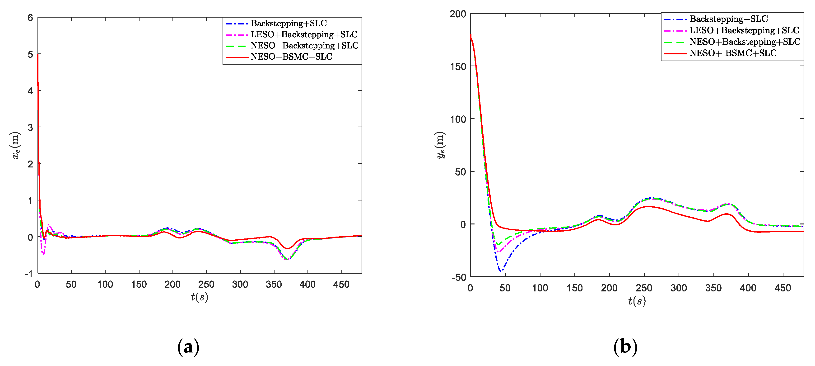
The comparison of along-tracking errors, cross-tracking errors, and heading-tracking errors are shown in Figure 4. It can be shown that the proposed NESO-based backstepping sliding mode control (BSMC) scheme can improve both the transient and steady state tracking errors of the path following for the underactuated hovercraft compared with traditional backstepping control, LESO-based backstepping control, and NESO-based backstepping control schemes.
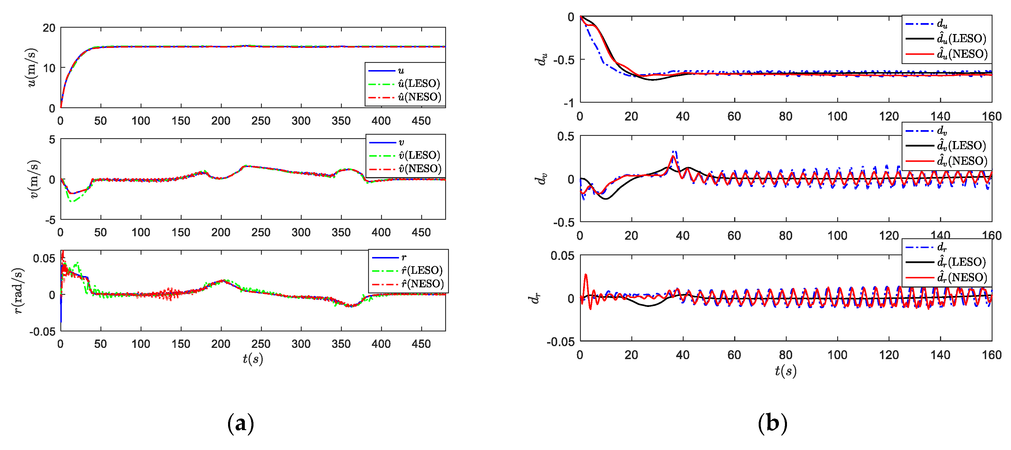
The simulation results of ESO for an underactuated hovercraft are shown in Figure 5. The estimation of velocities for a certain underactuated hovercraft is shown in Figure 5a, which indicates that the proposed NESO has higher accuracy and better transient performance than the LESO proposed in [12]. The approximations of the unknown nonlinear time-varying total uncertainties are plotted in Figure 5b, which show that the time-varying uncertainties can be approximated by NESO but not by LESO.
Remark 9.
The designed control scheme is robust to the system model. Since the relative wind speed and orientation are time-varying for the hovercraft, the dynamic system of the hovercraft has great time-varying uncertainty. The control simulation results show that the control method does not rely on the accurate model and is robust to the total uncertainties caused by external disturbances and unmodeled factors.
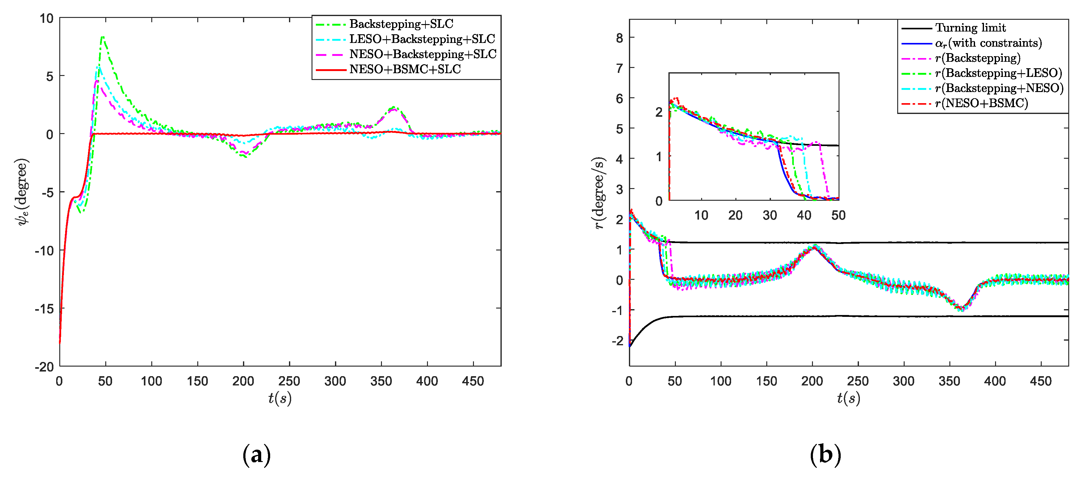
Figure 6 shows that the designed control strategy can make the constraint of the nonlinear time-varying turning safety limit possible by introducing an auxiliary variable to achieve the nonlinear time-varying constraint of virtual control. This can significantly improve the safety of the underactuated hovercraft.
Remark 10.
Compared with the control methods in the literature [25], the yaw controller with the safety limit was designed by control input constraint. However, the safety turning SLC parameter is not directly introduced into the control system, so the constraint effect is not accurate. In our control scheme, the auxiliary limiting variable is introduced into the backstepping process, and the safety limit is directly introduced into the control system. In addition, we consider the nonlinear time-varying turning SLC, which is not taken into the control design in reference [25].
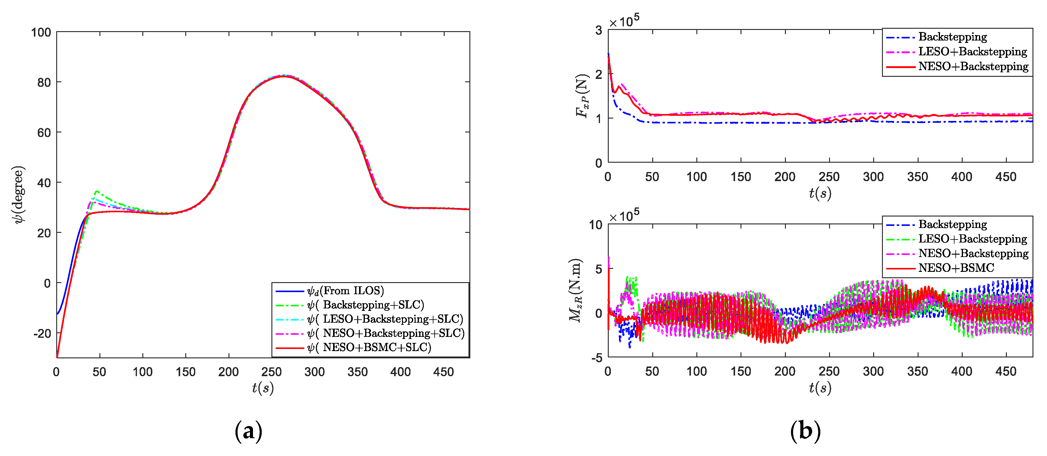
The heading curve of underactuated hovercraft under nonlinear time-varying turning SLC is shown in Figure 7a, which illustrates the heading-tracking error of the underactuated hovercraft converges to zero under the constraint of the nonlinear time-varying turning safety limit.
Remark 11.
Due to the restriction of the safety limit on the turning velocity, the heading-tracking error slowly approaches zero rather than converges rapidly to zero like that of the control method without SLC. Although the control method without the safety constraint is fast, it does not take the safety factors into account and easily leads to ship capsizing accidents caused by improper control.
Figure 7b shows the designed safe yaw and surge control inputs in terms of Theorem 2. It can be known that the proposed disturbances rejection using the NESO-based BSMC law has better stability and smoothness than other control schemes.

5. Conclusions

A safe control strategy has been presented for underactuated hovercrafts subject to nonlinear time-varying safety limit constraints and nonlinear time-varying uncertainties. A NESO is first proposed to estimate and compensate the nonlinear time-varying uncertainties of underactuated hovercrafts. The nonlinear time-varying turning safety limit is first considered in the controller design to improve the safety of underactuated hovercrafts. Theoretical analyses have indicated that the approximation errors of the NESO and the tacking errors of the closed-loop in the designed control system are bounded. The designed safe control strategy is applied on a certain underactuated hovercraft to verify the effectiveness of the designed control law. Theories and the application case have shown that the disturbances rejection safe control strategy greatly improves the safety and maneuverability of the underactuated hovercraft subjects to nonlinear time-varying uncertainties and the safety limit constraint. Even though this novel control methodology was described and validated in terms of an underactuated hovercraft, it also can be used to control other underactuated marine surface vehicles at constant altitudes.

Author Contributions

Conceptualization, H.T.; methodology, H.T.; software, H.T.; validation, H.T.; formal analysis, H.T.; writing—original draft preparation, H.T.; writing—review and editing, H.T. and H.R.; supervision, Y.W. and H.R.; funding acquisition, Y.W. All authors have read and agreed to the published version of the manuscript.

Funding

This research was supported by the China Scholarship Council (CSC201906680026), the National Natural Science Foundation of China under Grant No.51879049, and the National Natural Science Foundation of Heilongjiang Province under Grant No. LH2019E039, and the Fundamental Research Funds for the Central Universities under Grant No. 3072020CF0403.

Acknowledgments

I would like to express my gratitude to all those who helped me during the writing of this paper, especially my supervisors Wang and Ren who have offered me valuable suggestions in the academic studies. I am also very grateful to the reviewers for their comments that are of great help to improve the quality of this paper.

Conflicts of Interest

The authors declare no conflict of interest.

References

  1. Park, B.S.; Kwon, J.W.; Kim, H. Neural network-based output feedback control for reference tracking of underactuated surface vessels. Automatica 2017, 77, 353–359. [Google Scholar] [CrossRef]
  2. Fu, M.; Gao, S.; Wang, C.; Li, M. Design of driver assistance system for air cushion vehicle with uncertainty based on model knowledge neural network. Ocean Eng. 2019, 172, 296–307. [Google Scholar] [CrossRef]
  3. Kaya, K.; Özcan, O. A numerical investigation on aerodynamic characteristics of an air-cushion vehicle. J. Wind Eng. Ind. Aerodyn 2013, 120, 70–80. [Google Scholar] [CrossRef]
  4. Yun, L.; Bliault, A. Theory & Design of Air Cushion Craft; Elsevier Butterworth-Heinemann: London, UK, 2000. [Google Scholar]
  5. Cabecinhas, D.; Batista, P. Hovercraft Control With Dynamic Parameters Identification. IEEE Trans. Control Syst. Technol. 2018, 26, 785–796. [Google Scholar] [CrossRef]
  6. Fantoni, I.; Lozano, R.; Mazenc, F.; Pettersen, K.Y. Stabilization of a nonlinear underactuated hovercraft. In Proceedings of the 38th Conference on Decision & Control, Phoenix, AZ, USA, 7–10 December 1999; pp. 2533–2538. [Google Scholar]
  7. Peng, Z.; Wang, J.; Wang, J. Constrained Control of Autonomous Underwater Vehicles Based on Command Optimization and Disturbance Estimation. IEEE Trans. Ind. Electron. 2019, 66, 3627–3635. [Google Scholar] [CrossRef]
  8. Huang, Y.S.; Wu, M. Robust decentralized direct adaptive output feedback fuzzy control for a class of large-sale nonaffine nonlinear systems. Inf. Sci. 2011, 181, 2392–2404. [Google Scholar] [CrossRef]
  9. Chen, M.; Ge, S.S. Adaptive Neural Output Feedback Control of Uncertain Nonlinear Systems With Unknown Hysteresis Using Disturbance Observer. IEEE Trans. Ind. Electron. 2015, 62, 7706–7716. [Google Scholar] [CrossRef]
  10. Han, J. From PID to Active Disturbance Rejection Control. IEEE Trans. Ind. Electron. 2009, 56, 900–906. [Google Scholar] [CrossRef]
  11. Huang, Y.; Xue, W. Active disturbance rejection control: Methodology and theoretical analysis. ISA Trans. 2014, 53, 963–976. [Google Scholar] [CrossRef]
  12. Guo, B.; Zhao, Z. On the convergence of an extended state observer for nonlinear systems with uncertainty. Syst. Control Lett. 2011, 60, 420–430. [Google Scholar] [CrossRef]
  13. Liu, L.; Wang, D.; Peng, Z. State recovery and disturbance estimation of unmanned surface vehicles based on nonlinear extended state observers. Ocean Eng. 2019, 171, 625–632. [Google Scholar] [CrossRef]
  14. Peng, Z.; Wang, J.; Han, Q. Path-Following Control of Autonomous Underwater Vehicles Subject to Velocity and Input Constraints via Neurodynamic Optimization. IEEE Trans. Ind. Electron. 2019, 66, 8724–8732. [Google Scholar] [CrossRef]
  15. Gu, N.; Wang, D.; Peng, Z.; Liu, L. Distributed containment maneuvering of uncertain under-actuated unmanned surface vehicles guided by multiple virtual leaders with a formation. Ocean Eng. 2019, 187, 105996. [Google Scholar] [CrossRef]
  16. Wu, Z.; Guo, B. Extended State Observer for MIMO Nonlinear Systems with Stochastic Uncertainties. Int. J. Control 2020, 93, 424–436. [Google Scholar] [CrossRef]
  17. Lamraoui, H.C.; Zhu, Q. Path following control of fully-actuated autonomous underwater vehicle in presence of fast-varying disturbances. Appl. Ocean Res. 2019, 86, 40–46. [Google Scholar] [CrossRef]
  18. Dunbar, W.B.; Saber, R.O.; Murray, R.M. Nonlinear and cooperative control of multiple hovercraft with input constraints. In Proceedings of the European Cotrol Conference (ECC), Cambridge, UK, 1–4 September 2003; pp. 1917–1922. [Google Scholar]
  19. Tanaka, K.; Wasaki, M.I.; Wang, H.O. Switching Control of an R/C Hovercraft: Stabilization and Smooth Switching. IEEE Trans. Syst. Man Cyber. 2001, 31, 853–863. [Google Scholar] [CrossRef]
  20. Morales, R.; Sira-Ramírez, H.; Somolinos, J.A. Linear active disturbance rejection control of the hovercraft vessel model. Ocean Eng. 2015, 96, 100–108. [Google Scholar] [CrossRef] [Green Version]
  21. Sira-Ramírez, H. Dynamic Second-Order Sliding Mode Control of the Hovercraft Vessel. IEEE Trans. Control Syst. Technol. 2002, 10, 860–865. [Google Scholar] [CrossRef]
  22. Jeong, S.; Chwa, D. Coupled Multiple Sliding-Mode Control for Robust Trajectory Tracking of Hovercraft With External Disturbances. IEEE Trans. Ind. Electron. 2018, 65, 4103–4113. [Google Scholar] [CrossRef]
  23. Wei, X.; Cabecinhas, D. Robust Control of anUnderactuated Hovercraft. IEEE Trans. Control Syst. Technol. 2019, 27, 2195–2208. [Google Scholar]
  24. Lu, D.; Xie, W.; Cabecinhas, D.; Cunha, R.; Silvestre, C. Path Following Controller Design for an Underactuated Hovercraft with External Disturbances. In Proceedings of the 19th International Conference on Control, Automation and System, Jeju, Korea, 15–18 October 2019; pp. 76–81. [Google Scholar]
  25. Fu, M.; Gao, S. Safety-Guaranteed Trajectory Tracking Control for the Underactuated Hovercraft with State and Input Constraints. Math. Probl. Eng. 2017, 2017, 9452920. [Google Scholar] [CrossRef] [Green Version]
  26. Fu, M.; Wang, T. Barrier Lyapunov Function-Based Adaptive Control of an Uncertain Hovercraft with Position and Velocity Constraints. Math. Probl. Eng. 2019, 2019, 1940784. [Google Scholar] [CrossRef]
  27. Rosier, L. Homogeneous Lyapunov function for homogeneous continuous vector field. Syst. Control Lett 1992, 19, 467–473. [Google Scholar] [CrossRef]
  28. Bhat, S.P.; Bernstein, D.S. Geometric homogeneity with applications to finite-time stability Systems. Math. Control Signals 2005, 17, 101–127. [Google Scholar] [CrossRef] [Green Version]
  29. Khalil, H.K. Nonlinear Systems, 3rd ed.; Prentice Hall: Prentice Hall, NJ, USA, 2002. [Google Scholar]
  30. Wang, Y.; Tong, H.; Wang, C. High-gain observer based line-of-sight guidance for adaptive neural path following control of underactuated marine surface vessels. IEEE Access 2019, 7, 26088–26101. [Google Scholar] [CrossRef]
  31. Wang, Y.; Tong, H.; Fu, M. Line-of-sight guidance law for path following of amphibious hovercrafts with big and time-varying sideslip compensation. Ocean Eng. 2019, 172, 531–540. [Google Scholar] [CrossRef]
  32. Borhaug, E.; Pavlov, A.; Pettersen, K.Y. Integral LOS control for path following of underactuated marine surface vessels in the presence of constant ocean currents. In Proceedings of the 47th IEEE Conference on Decision and Control, Cancun, Mexico, 9–11 December 2008; pp. 4984–4991. [Google Scholar]
  33. Lekkas, A.M.; Fossen, T.I. A Time-Varying Lookahead Distance Guidance Law for Path Following. In Proceedings of the 9th IFAC Conference on Manoeuvring and Control of Marine Craft, Arenzano, Italy, 19–21 September 2012; pp. 398–403. [Google Scholar]
  34. Wang, N.; Sun, J.; Er, M.J. Tracking-error-based universal adaptive fuzzy control for output tracking of nonlinear systems with completely unknown dynamics. IEEE Trans. Fuzzy Syst. 2018, 26, 869–883. [Google Scholar] [CrossRef]
  35. Fossen, T.I. Handbook of Marine Craft Hydrodynamics and Motion Control, 1st ed.; John Wiley & Sons Ltd.: West Sussex, UK, 2011. [Google Scholar]
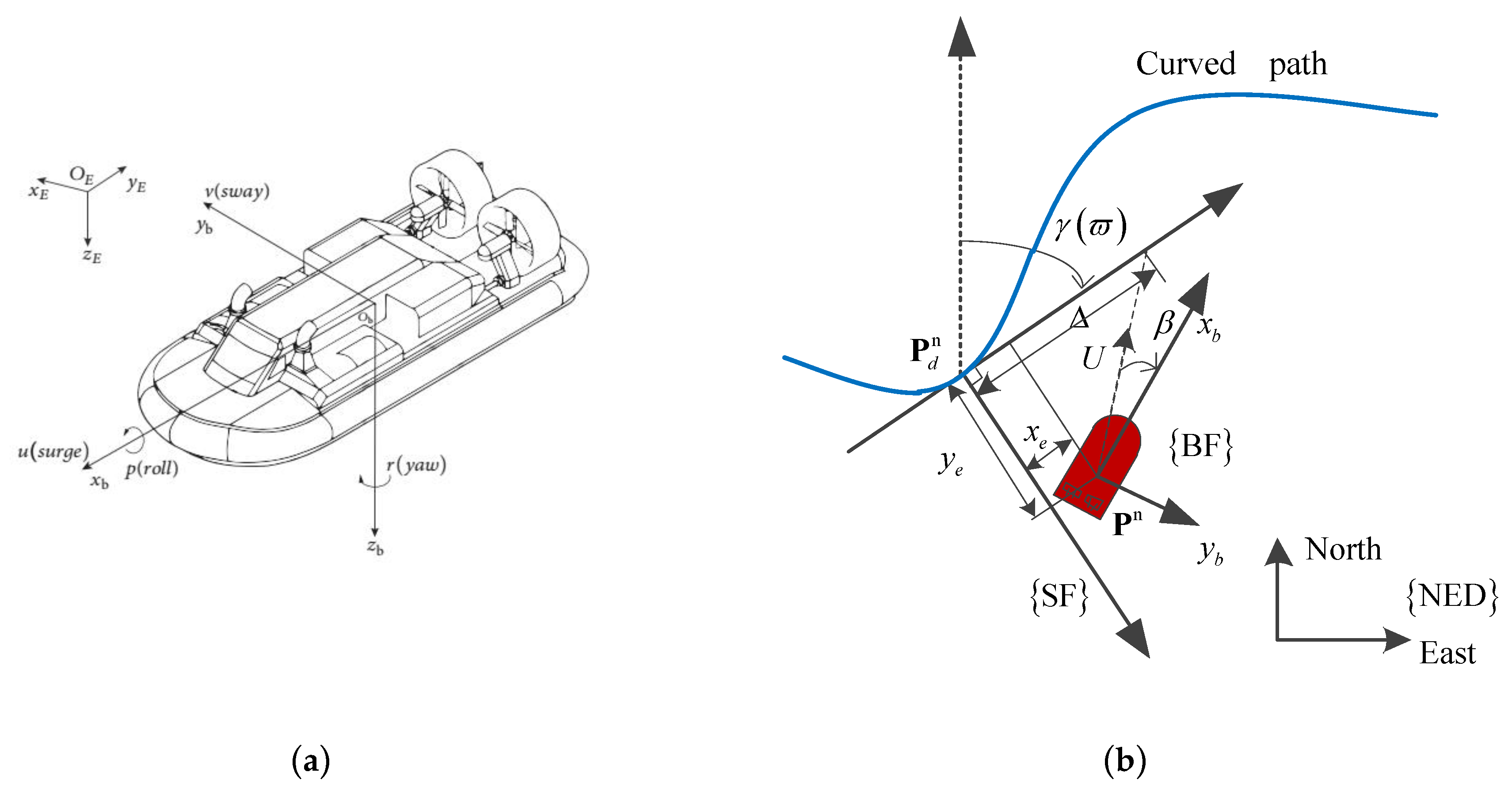
Figure 1. (a) An underactuated hovercraft in the horizontal plan; (b) the geometric schematic diagram of line-of-sight (LOS) guidance.
Applsci 10 05287 g001
Figure 2. (a) The nonlinear time-varying turning safety limit of an underactuated hovercraft; (b) the diagram of the designed safe control strategy for the path following of underactuated hovercrafts.
Applsci 10 05287 g002
Figure 3. The curved path following results. (a) The path following results of the proposed safe control strategy; (b) the path following tracking errors x e , y e , and ψ e of the proposed control scheme.
Applsci 10 05287 g003
Figure 4. The comparison of tracking errors from different control schemes. (a) The comparison of along-tracking errors; (b) the comparison of cross-tracking errors.
Applsci 10 05287 g004
Figure 5. The simulation results of the extended state observer (ESO) for an underactuated hovercraft. (a) The estimated velocities using the proposed nonlinear extended state observer (NESO) and the linear extended state observer (LESO); (b) the approximated total uncertainties using the proposed NESO and the LESO.
Applsci 10 05287 g005
Figure 6. (a) The comparison of heading-tracking errors from different control schemes; (b) the comparison of the virtual control and the true control law with the safety limit constraint (SLC).
Applsci 10 05287 g006
Figure 7. (a) The comparison of heading angle from different control schemes; (b) the comparison of yaw and surge control forces with different control schemes.
Applsci 10 05287 g007
Table 1. The waypoints data base for the curved path of the underactuated hovercraft.
WaypointsWpt0Wpt1Wpt2Wpt3Wpt4Wpt5Wpt6 1
x ( m ) 0130025002700300038005100
y ( m ) 070015002700370043005000
1 Wpt represents the number of waypoints.