Article

Adaptive Cruise Control for Eco-Driving Based on Model Predictive Control Algorithm

1
Interdisciplinary Graduate School of Engineering Sciences, Kyushu University, Fukuoka 816-8580, Japan
2
Platform of Inter/Transdisciplinary Energy Research, Kyushu University, Fukuoka 819-0395, Japan
*
Author to whom correspondence should be addressed.
Appl. Sci. 2020, 10(15), 5271; https://doi.org/10.3390/app10155271
Submission received: 15 July 2020 / Revised: 27 July 2020 / Accepted: 29 July 2020 / Published: 30 July 2020
(This article belongs to the Special Issue Future Intelligent Transportation System for Tomorrow and Beyond)

Abstract

:
An adaptive cruise control (ACC) system is developed based on eco-driving for two typical car-following traffic scenes. The ACC system is designed using the model predictive control (MPC) algorithm, to obtain objectives of eco-driving, driving safety, comfortability, and tracking capability. The optimization of driving comfortability and the minimization of fuel consumption are realized in the manner of constraining the acceleration value and its variation rate, so-called the jerk, of the host vehicle. The driving safety is guaranteed by restricting the vehicle spacing always larger than minimum safe spacing from the host vehicle to the preceding vehicle. The performances of the proposed MPC-based ACC system are evaluated and compared with the conventional proportional-integral-derivative (PID) controller-based ACC system in two representative driving scenarios, through a simulation bench and an instantaneous emissions and fuel consumption model. In addition to meeting the other driving objectives mentioned above, the simulation results indicate an improvement of 13% (at the maximum) for fuel economy, which directly shows the effectiveness of the presented MPC-based ACC system.

1. Introduction

Reducing fuel consumption, carbon dioxide (CO2), and other air pollution emission has been an impending sustainable problem facing the transportation sector, especially the automobile industry, which is currently stalemating over oil scarcity and environmental concerns. Therefore, policymakers and automobile manufacturers have been exploring numerous strategies and products to minimize fuel consumption and emissions. Approaches to achieving the reduction of fuel consumption are diverse, such as advanced engine technology, intelligent vehicle technology, and new energy technology, like pure electric vehicle and hybrid electric vehicle [1]. Among these strategies and products, eco-driving, as one of the new control technologies, has been widely noted because of its potential of reducing fuel consumption in whatever the local microscopic or global macroscopic level [2,3,4,5,6,7,8,9]. The main concept of eco-driving is to offer the driver an optimal driving strategy or replace the driver with advanced driver assistance systems (ADAS,) to improve the fuel economy under the guise of satisfying the driving time and speed limits. The primary objective of eco-driving is to adapt the host vehicle to its driving surroundings, including road condition and traffic flow, so that the fuel consumption and exhaust emissions can be minimized.
Eco-driving research related to the idea of controlling the vehicle speed for minimizing fuel consumption has been around a long time. Studies for optimizing vehicle cruise speed in terms of its driveline operation condition have been conducted, without considering the effect of traffic surroundings and road information [10,11]. Fuel economy for road vehicles not only depends on the performance of drivetrain inside the vehicle; it also depends on its operation—this was first proposed by Leipnik and Schwarzkopf in 1977 [12]. Utilizing an optimal hybrid powertrain and traffic flow data obtained by intelligent transportation technologies, reducing the fuel consumption driving on the urban road can be achieved [13]. Fuel economy can be improved by forecasting required engine torque and optimized speed profile, with the combination of comprehensive traffic information and a model predictive controller [14]. However, the previously mentioned approaches are impractical to real-time optimization and calculation, because of lacking the integrated driving behavior before travel.
In addition to optimal driving strategies in terms of automatic operation of a vehicle, a variety of eco-driving assistance functions have been applied in a real-time driving scenario. A green “ECO” indicator has been used for displaying if the current driving behavior is fuel economic or not. A research work to determine the optimum driving strategy of a vehicle based on eco-driving rules has been done by Saboohi and Farzaneh [15]. However, only the model of the engine in terms of vehicle speed, gear ratio, and load is considered. Another work that fully responds to the road condition, upcoming traffic signals, and spacing between vehicles of the real driving scene can generate rough driving behavior advice, such as speed up or slow down, to the user [16]. Nevertheless, these eco-driving assistance approaches are more about giving driving guidance qualitatively, rather than providing quantitative velocity or acceleration data required for fuel economy assessment.
The current existing eco-driving system can be classified into three categories: before the traveling scheme, during traveling scheme, and after traveling scheme according to the time of data processing. Due to a greater extent of real-time interaction and engagement with traffic flow and road conditions, the during-traveling scheme eco-driving system, as a branch of rapidly developed advanced driver assistance systems (ADASs), has been strikingly concerned academically. Adaptive cruise control (ACC) is an automated vehicle control system of ADASs, and safe car-following is the basic task of developing the ACC system. Besides the objective of safe car-following, driving comfortability is of great significance when promoting the performance of ACC system, according to the report on ACC by the National Highway Traffic Safety Administration (NHTSA) [17]. Hence, if the target of the controlled host vehicle in the ACC system is to reduce fuel consumption as well as securing driving safety, guaranteeing the car-following and driving comfortability, an ACC system with multi-objectives must be developed. Many scholars have been working on designing different control strategies for the ACC system, including classic proportional-integral-derivative (PID) control, linear quadratic regulator (LQR) control, sliding mode control, neural network and machine learning, fuzzy logic control, and model predictive control (MPC) [18,19,20,21]. To achieve the research goal, the MPC framework is adopted to design the ACC system, because MPC has the preview capability to predict future state within a prediction horizon and the characteristic of receding horizon optimization for performance evaluation index under restricted conditions. Compared with existing microscopic and macroscopic traffic simulation models, such as Gipps’ model, Newell model, cellular automata model, IDM model, etc., elaborated in [22], MPC may handle the traffic-imposed constraints more systematically.
As an emerging research topic recently, introducing the MPC algorithm into the ACC system has been provided with high interest academically. Based on the design of the intelligent ACC system, the feasibility of applying a hybrid MPC framework into vehicle tracking control was studied [23]. The simulation results validated the effectiveness and industrial viability of the developed hybrid MPC algorithm. A multi-objective coordinated optimization strategy for the ACC system was designed based on the MPC method, which includes tracking capability, driving comfortability, and minimizing fuel consumption [24,25]. However, the distinctness of the cut-in driving situation and related specifics of designing an MPC-based ACC system is not clearly explained. Furthermore, the concrete fuel economy performance improvement of the proposed MPC-based ACC system compared with the classic controller-based ACC system is not clarified.
Accordingly, a new multiple objectives ACC optimization strategy in the framework of MPC is explored in this brief. The proposed method can be implemented practically in real-time optimization by quantitatively providing an acceleration command to achieve eco-driving. Besides, it covers the shortage of existing microscopic traffic models in handling multiple traffic-related constraints. Most importantly, it offers a possible solution for reducing fuel consumption, to realize eco-driving as well as improving the driving comfortability compared with the existing PID-based ACC system, which pales in considering comfort and fuel economy. The kinematic relationship between the preceding and the host vehicles is depicted in Figure 1. An ACC-equipped vehicle can follow an expected spacing when a preceding vehicle is detected, or follow a desired predefined velocity if no vehicle is running ahead. It considers the basic traffic situation—car-following process, during which, with a combination of MPC algorithm, an ACC-equipped vehicle simultaneously is capable of achieving the objective of eco-driving—improving the fuel economy. The contribution of this paper are as follows: to begin with, the “Bicycle model” for vehicle dynamics is established for the host vehicle. Next, the longitudinal dynamics ACC system model is developed. In the proposed ACC system model, not only the inter-distance and speed error between host and preceding vehicles are considered, but also the acceleration and acceleration variation rate, jerk, of host vehicle are included. The objective of fuel economy is achieved mainly by setting constraints to acceleration and jerk. Finally, the proposed MPC-based ACC system is compared with the classic ACC system in the framework of PID controller to assess the fuel economy improvement of the proposed new ACC system.
The rest of this paper is constructed as follows: Section 2 includes the main materials and research methods, wherein the bicycle model for host vehicle dynamics is described in Section 2.1, Section 2.2 describes the longitudinal dynamic ACC system model, main control objectives and relevant constraints, a multi-objective algorithm, including the eco-driving performance index, fuel economy, is projected in the framework of MPC in Section 2.3, an instantaneous emissions and fuel consumption model is applied to calculate the emissions factor and fuel economy in Section 2.4, Section 2.5 describes the overall simulation environment and structure. In Section 3, the simulation results and discussion of the proposed algorithm are provided, followed by the conclusions in Section 4.

2. Materials and Methods

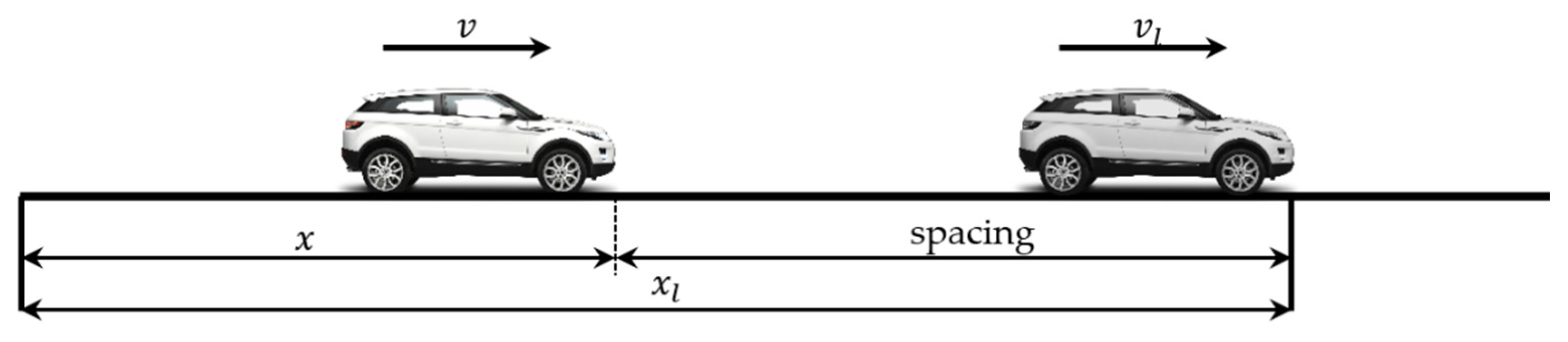
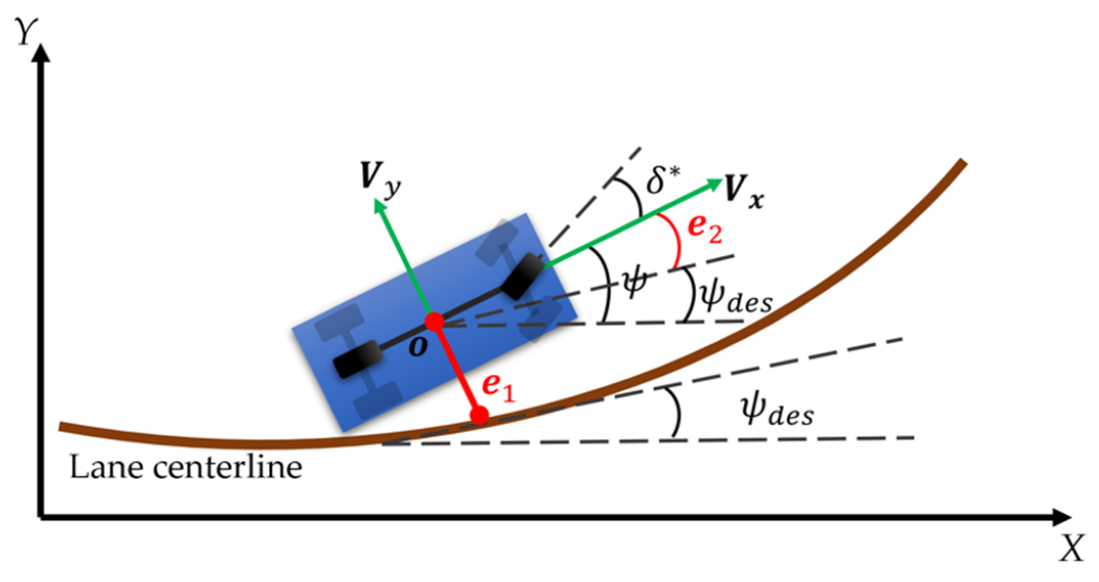
2.1. Vehicle Dynamics Modeling

In this research, the bicycle model is adopted to describe the host vehicle dynamic explicitly. The whole control input of this model can be simplified as two parameters, the longitudinal acceleration c , and the front steering angle δ * . The dynamic bicycle model diagram is presented in Figure 2.
The state vector for this dynamic bicycle model is defined as:
s = [ V y , ψ , ψ ˙ , V x , V ˙ x ] T
According to the analysis of longitudinal and lateral force interacting with tires, the first derivative of the state vector with respect to time can be approximated as follows [26]:
d s d t = d d t [ V y ψ ψ ˙ V x V x ˙ ] = [ 2 C f + 2 C r m V x 0 V x 2 C f l f 2 C r l r m V x 0 0 0 0 1 0 0 2 C f l f 2 C r l r I z V x 0 2 C f l f 2 + 2 C r l r 2 I z V x 0 0 0 0 0 0 1 0 0 0 0 1 τ ] [ V y ψ ψ ˙ V x V x ˙ ] + [ 2 C f m 0 2 C f l f I z 0 0 ] δ * + [ 0 0 0 0 1 τ ] c + [ 0 0 0 V y ψ ˙ 0 ]
where, V y refers to the host vehicle lateral velocity, V x represents the longitudinal velocity, V x ˙ refers to the derivative of longitudinal velocity, the longitudinal acceleration, ψ refers to the yaw angle,   ψ ˙ refers to the variation rate of yaw angle, m refers to the total mass of the host vehicle, I z denotes the yaw moment of inertia of host vehicle, l f and l r represent the longitudinal distance from the center of gravity to front and rear tires, respectively, C f and C r represent the tires cornering stiffness, and τ refers to the longitudinal time constant.
The outputs from the vehicle dynamics, such as longitudinal velocity V x and lateral velocity V y are based on vehicle body coordinates. The goal of steering model is to keep the vehicle within its lane and follow the predefined road path, by controlling the front steering angle δ * , which is achieved by driving the yaw angle error e 2 and lateral displacement error e 1 to zero, where
e 1 = V x e 2 + V y
e 2 = ψ ψ d e s
The desired yaw angle rate is calculated by V x R , where R refers to the radius of the road curvature.

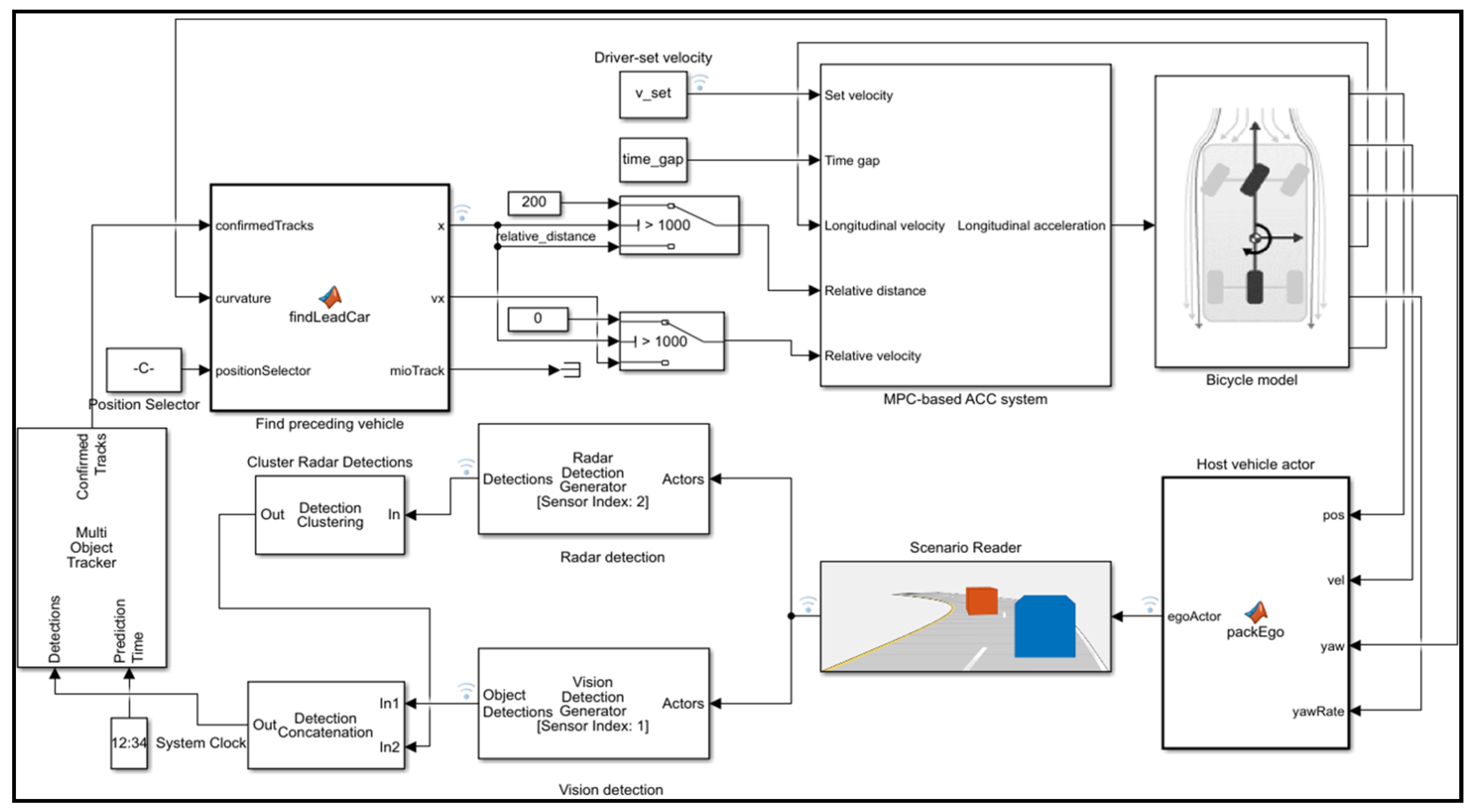
2.2. Adaptive Cruise Control System Modeling

An actual ACC system being implemented is hierarchically distributed into two levels: an upper adaptive algorithm and a lower maneuver controller [27]. The acceleration command coming from the upper adaptive algorithm is fed as the input command into the lower maneuver controller. The required dynamics of the vehicle, as well as the constraints, are determined by the upper adaptive algorithm of the ACC system; the lower maneuver controller receives the acceleration command from the upper adaptive algorithm, to control the open-close degree of the throttle and state of the brake. Since this research concerns more the interaction with external driving conditions, such as the traffic flow situation, the upper-level algorithm design is the focus. In this case, the behavior of the lower-level controller can be approximated as a first-order system [28,29].
τ d a ( t ) d t + a ( t ) = c ( t )
where τ represents the time lag of the lower-level controller, a refers to the acceleration of the host ACC-equipped vehicle, c denotes the acceleration command output by the upper adaptive algorithm.
Adopting the difference approximation method, the discretization expression for (5) can be obtained as [30]:
τ a ( t + 1 ) a ( t ) T s + a ( t ) = c ( t )
where a ( t ) ,   c ( t ) refer to the acceleration and the control command of the ACC-equipped vehicle at the sampling time t , separately, and T s represents the sampling period.
The desired time headway mechanism is considered [31]:
D T H ( t ) = x 0 + θ c · v ( t )
where D T H ( t ) refers to the desired vehicle spacing at sampling time t , x 0 represents a fixed safe spacing as the vehicle speed goes to a low value or zero, θ c denotes the desired time headway, and v ( t ) is the actual velocity at time t .
The vehicle spacing Δ x ( t ) can be defined as [30]:
Δ x ( t ) = Δ x ( t 1 ) + [ v l ( t 1 ) · T s + 1 2 a l ( t 1 ) · T s 2 ] [ v ( t 1 ) · T s + 1 2 a ( t 1 ) · T s 2 ]
where Δ x ( t ) refers to the actual spacing between host and preceding vehicle at the sampling moment t , a l is the acceleration of the vehicle operating ahead, v l = v + Δ v , is the velocity of the vehicle operating ahead, Δ v denotes the velocity difference between the host and preceding vehicles.
The derivative of vehicle acceleration can be derived as jerk [32]:
J ( t ) = a ( t ) a ( t 1 ) T s
The dynamics of an ACC-equipped vehicle can be expressed by the state-space equations:
x ( t ) = C 0 x ( t 1 ) + C 1 c ( t 1 ) + C 2 a l ( t 1 )
y ( t 1 ) = C 3 x ( t 1 ) C 4
Here, the system matrices can be obtained as follows:
C 0 = [ 1 0 0 1 a 1 a 2 0 0 a 1 0 0 0 0 0 0 0 1 a 1 0 0 a 3 0 0 a 4 0 ]   ,   C 1 = [ 0 0 0 a 5 a 6 ] ,   C 2 = [ a 7 0 a 8 0 0 ] , C 3 = [ 1 a 9 0 0 0 0 0 1 0 0 0 0 0 0 0 1 0 0 0 1 ] ,   C 4 = [ a 10 0 0 0 ]
a 1 = T s ,   a 2 = 1 2 T s 2 ,   a 3 = 1 T s τ ,   a 4 = 1 τ   ,   a 5 = T s τ ,   a 6 = 1 τ   ,   a 7 = 1 2 T s 2 ,   a 8 = T s ,   a 9 = θ c   and   a 10 = x 0
The upper adaptive algorithm of the ACC system is formed to achieve eco-driving and other multiple objectives, including driving fuel-economically comfortably and safely during a car-tracking process.
The performance of the car-following of the ACC system is required to meet the demand for following preceding vehicle stably. If the actual vehicle spacing is too large, it will not only reduce the utilization of the road, but also cause the vehicle on the neighboring lanes frequently, cutting into the host vehicle lane. And a small vehicle spacing can increase the possibility of rear-end collision, which will make the driver feel nervous. The following capability is mainly guaranteed by reaching the relative speed Δ v and vehicle spacing error δ to zero, i.e., making two vehicles in a relatively static state.
Car - following   objective :   { δ ( t )     0 Δ v ( t ) 0   ,   as   t .
where
δ ( t ) = Δ x ( t ) D T H ( t )
Δ v ( t ) = v l ( t ) v ( t )
According to [33], to achieve the objective of driving comfortability, the vehicle speed firstly should be kept at a constant value as far as possible, so that the acceleration is constrained within a certain range to avoid significant changes. Secondly, the variation rate of the host vehicle’s acceleration should be as low as possible. Therefore, in this paper, the absolute value of acceleration and its variation rate are selected as the quantitative characterization index of the ACC system’s comfortability. The optimization objective can be defined as:
Driving   comfortability   objective :     { min | a ( t ) | min | J ( t ) | ,
Simultaneously, the acceleration and its variation rate are constrained as:
{ a m i n a ( t ) a m a x J m i n J ( t ) J m a x
According to the main purpose of the eco-driving of minimizing fuel consumption, fuel consumption is mainly related to vehicle acceleration [25]. Under the condition of the same average driving speed and driving distance, fuel consumption increases, along with the increase of the absolute value of acceleration. Therefore, the better the vehicle driving comfortability, the higher the fuel economy. So, the driving comfortability evaluation index can be used indirectly as the index of fuel economy. In addition to the above constraints, the absolute value of acceleration command output by the upper-level controller of the ACC system should also be constrained.
c m i n c c m a x
where c m i n and c m a x are the minimum and maximum values of expected acceleration, respectively.
To avoid an accident to guarantee the safety when tracking the preceding vehicle, the vehicle spacing between the host ACC-equipped vehicle and the preceding vehicle must be greater than a critical minimum distance, x m i n . Due to the unallowable reason for the collision, this constraint is set as a hard one.
Hard   constraint :   Δ x ( t ) x m i n .
Besides, considering the regulation of traffic law and the limitation of the vehicle’s own physical ability, the speed of the vehicle in the process of driving needs to be set as a hard constraint in this paper.
v m i n v v m a x
Based on the above analysis, the ACC system, eco-driving objective, and other multiple objectives, including car-following capability, driving comfortability, and safety, are studied and modeled step by step; different design objectives are described as different optimization equation and constraints. Then, the design of the upper-level controller of the ACC system could be conducted within the MPC framework.

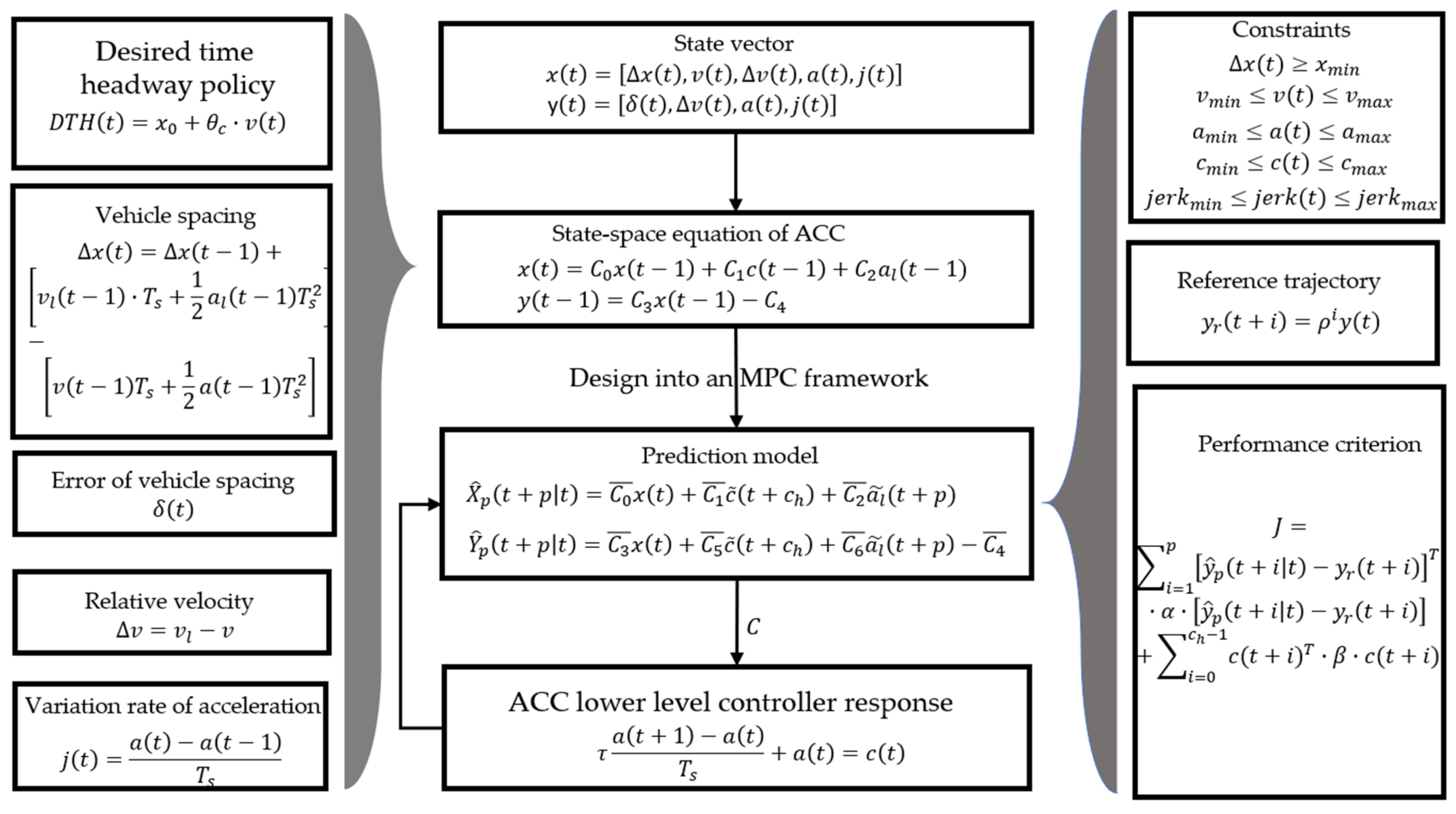
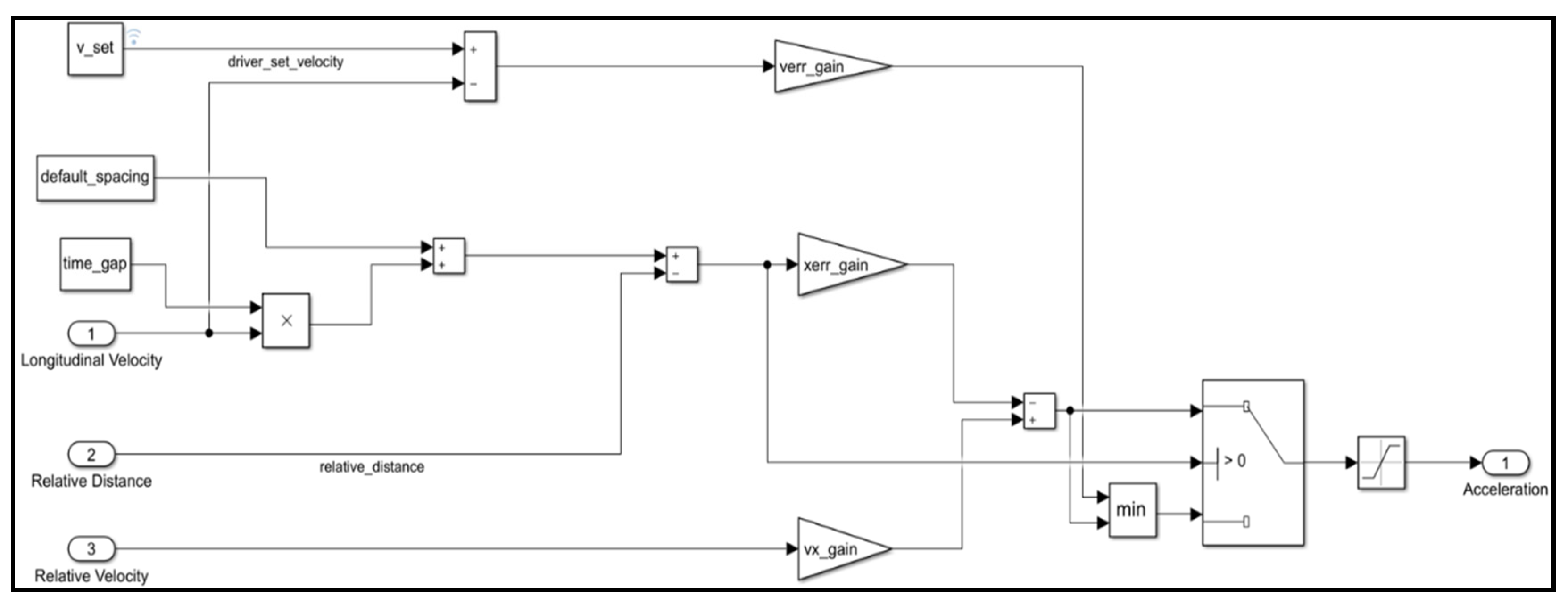
2.3. Framework of Model-Predictive Controller

The fundamental working mechanism of the MPC can be generalized as follows: future system action is forecasted based on the predictive model and system current state at each sampling moment. The feedback scheme is used to optimize the forecasting error. At the same time, the inaccuracy of the prediction model is corrected in the light of output. Then, through solving an online optimization problem, the optimal control sequence can be obtained, and the first value of this sequence is applied to regulate the system. Next, the control horizon goes a step forward, so that the MPC working mechanism is repeated. Thus, the core characteristics of MPC can be summarized as the predictive model, receding horizon optimization, and feedback correction, which qualifies the MPC for excellent control effect and good robustness [34]. Furthermore, MPC can cope with multiple inputs and multiple outputs systems. Moreover, these inputs and outputs are allowed to have interactions with each other. It can also set constraints for input and output, which makes it a preferential choice when planning and making a detailed design for the upper-level strategy of the ACC system. Utilizing the ACC system longitudinal dynamics model as the prediction model, the predictive state can be calculated as [30]:
X ^ p ( t + p | t ) = C 0 ¯ x ( t ) + C 1 ¯ c ˜ ( t + c h ) + C 2 ¯ a l ˜ ( t + p )
Y ^ p ( t + p | t ) = C 3 ¯ x ( t ) + C 5 ¯ c ˜ ( t + c h ) + C 6 ¯ a l ˜ ( t + p ) C 4 ¯
where
X ^ p ( t + p | t ) = [ x ^ p ( t + 1 | t ) x ^ p ( t + 2 | t ) x ^ p ( t + p | t ) ] ,   Y ^ p ( t + p | t ) = [ y ^ p ( t + 1 | t ) y ^ p ( t + 2 | t ) y ^ p ( t + p | t ) ] , c ˜ ( t + c h ) = [ c ( t ) c ( t + 1 ) c ( t + c h 1 ) ] ,   a l ˜ ( t + p ) = [ a l ( t ) a l ( t + 1 ) a l ( t + p 1 ) ] = [ a l ^ ( t 1 | t ) a l ^ ( t 1 | t ) a l ^ ( t 1 | t ) ] . , C 0 ¯ = [ C 0   C 0 2 C 0 p 1 ] ,   C 1 ¯ = [ C 1 0 0 C 0 C 1 C 1 0 C 0 p 1 C 1 C 0 p 2 C 1 C 0 p c h C 1 ] , C 2 ¯ = [ C 2 0 0 C 0 C 2 C 2 0 C 0 p 1 C 2 C 0 p 2 C 2 C 2 ] ,   C 3 ¯ = [ C 3 C 0 C 3 C 0 2 C 3 C 0 p 1 ] ,   C 4 ¯ = [ C 4 C 4 C 4 C 4 ] , C 5 ¯ = [ C 3 C 1 0 0 C 3 C 0 C 1 C 3 C 1 0 C 3 C 0 p 1 C 1 C 3 C 0 p 2 C 1 C 3 C 0 p c h C 1 ] ,   C 6 ¯ = [ C 3 C 2 0 0 C 3 C 0 C 2 C 3 C 2 0 C 3 C 0 p 1 C 2 C 3 C 0 p 2 C 2 C 3 C 2 ] ,
where p represents the predicted horizon, c h   denotes the control horizon, x ( t ) refers to the scaled state at the sampling moment t , the calculated control sequence denotes as c ( t ) , c ( t + 1 ) , …, c ( t + c h 1 ) , a l ^ denotes the acceleration of the preceding vehicle of sampling moment t 1 , but is measured at the current sampling moment t .
The multiple objectives of the ACC system, including eco-driving fuel economy improvement, driving comfortability, safety, and tracking capability are integrated into a performance evaluation standard J using weighting factor [30]:
J = i = 1 p [ y ^ p ( t + i | t ) y r ( t + i ) ] T · α · [ y ^ p ( t + i | t ) y r ( t + i ) ] + i = 0 c h 1 c ( t + i ) T · β · c ( t + i )
here,   β and   α are weighting factor matrices of control behavior and multiple objectives, respectively. From the last section analysis, it is known that the performance requirements of the ACC system are to make control outputs to track the reference inputs. Therefore, in order to achieve smooth control, the control output of the ACC system does not directly track the set value. On the contrary, it makes the dynamic response reach the new stable value along a specific and smooth curve. Hence, the exponential attenuation function is applied as the reference variation trajectory of the optimized vector. The reference variation trajectory is defined as [32]:
y r ( t + i ) = ρ i y ( t )
where ρ = e T 0 ε , T 0 and ε are sampling period and time constant of reference trajectory, respectively.
The objective of eco-driving fuel economy improvement, driving safety and physical limitation of the vehicle are regarded as constraints of MPC [30]:
s . t .   { Δ x ( t )   x min v min v ( t ) v max a min a ( t ) a max J e r k min J e r k ( t ) J e r k max c min c ( t ) c max
Accordingly, the multiple control objectives are synthesized based on the principle of MPC.
The above optimization problem can be described as a quadratic programming (QP) question [35].
In conclusion, at every sampling moment, the real-time vehicle inter-distance, speed difference, host vehicle speed, jerk, as well as acceleration are measured by the proposed ACC system. Using these measurements, the QP problem is solved to acquire the control sequence, and only the first value of the control sequence is adopted at every sampling moment to handle the whole ACC system. In such a way, the entire system operation course is iterated at the next sampling moment. The framework of the MPC-based ACC system is shown in Figure 3.

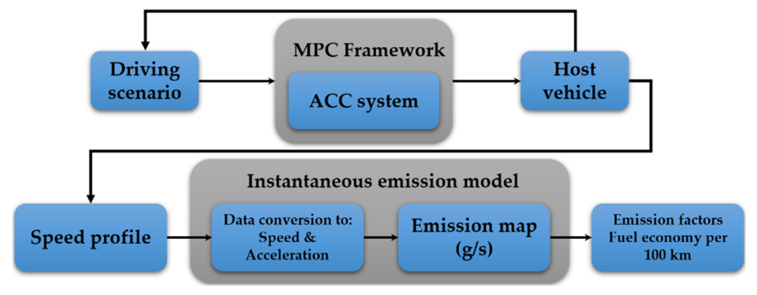
2.4. Emission and Fuel Consumption Model Development

To quantitatively assess the performance index of eco-driving, fuel consumption is required to calculate through a specific fuel consumption model. In this research, the white-box fuel consumption model is applied to calculate fuel consumption, which relies on the working principle of the vehicle engine cycle [1]. Carbon balance method (CBM) and mean value phenomenological model (MVPM) are the main constituent of white-box models. The basic methodology of the carbon balance theory is the mass conservation, i.e., the aggregate mass of carbon after combustion in the exhaust emissions theoretically is equal to the fuel carbon content before combustion. Then, the prediction and measurement of vehicle emissions are required. According to [36,37,38], acceleration and velocity, as the direct representation of driving behavior, can be utilized to characterize fuel consumption and exhaust emissions, i.e., exhaust emissions are primarily decided by vehicle speed and its acceleration. Consequently, the following instantaneous exhaust emissions and fuel consumption model is applied to calculate the performance index of eco-driving. The structure of where to obtain the input data and how it works are shown in Figure 4.
Emission data under a specific range of speed was collected from the Dynamometer Database of Argonne National Laboratory [39] to depict the emission maps, which shows each emission rate as a function of acceleration and speed.
The input data to the instantaneous exhaust emissions and fuel consumption model is a driving speed-time series profile. In the data conversion process, the speed is manifest provided by the driving cycle speed profile data. Taking the first derivative of speed in terms of time, the acceleration is obtained directly:
a t = v t v t 1 Δ t
where a t refers to the acceleration at current time t , v t and v t 1 are the vehicle speed at current time t and previous time t 1 , respectively. Moreover, Δ t is the speed profile time step.
After obtaining the emission rates for each emission constituent ( HC ,   CO ,   CO 2 ), the carbon mass conservation concept was taken to identify the fuel consumption in liters per 100 km of the vehicle [1].
F C = 0.1154 D ( 0.886 HC + 0.429 CO + 0.273 CO 2 )
where, F C denotes the fuel consumption per hundred kilometers in liters,   CO refers to carbon monoxide emission, HC refers to hydrocarbon emission, CO 2 refers to carbon dioxide emission, and D represents the gasoline density at 288 K.
Note that the vehicles discussed in this research are all conventional gasoline vehicles rather than hybrid or electric vehicles.

2.5. Simulation Environment

The overall simulation test bench is established in the MATLAB/Simulink environment, as shown in Figure 5. The structure of the PID controller for the ACC system is shown in Figure 6. The proposed closed-loop Simulink model is composed of the host vehicle dynamics module, sensor module, driving scenario module, sensor fusion and tracking module, and ACC system module. The ACC system is designed separately by a PID controller or an MPC controller, which can be switched optionally. The driving scenario module reads the velocity and position data of the host vehicle, and the camera and radar data. The sensor fusion and tracking module receive and process them into the relative velocity and distance. The longitudinal velocity from the vehicle dynamics module and relative distance and speed are input fed into the ACC system. The acceleration command is then transferred to control the action of the host vehicle.

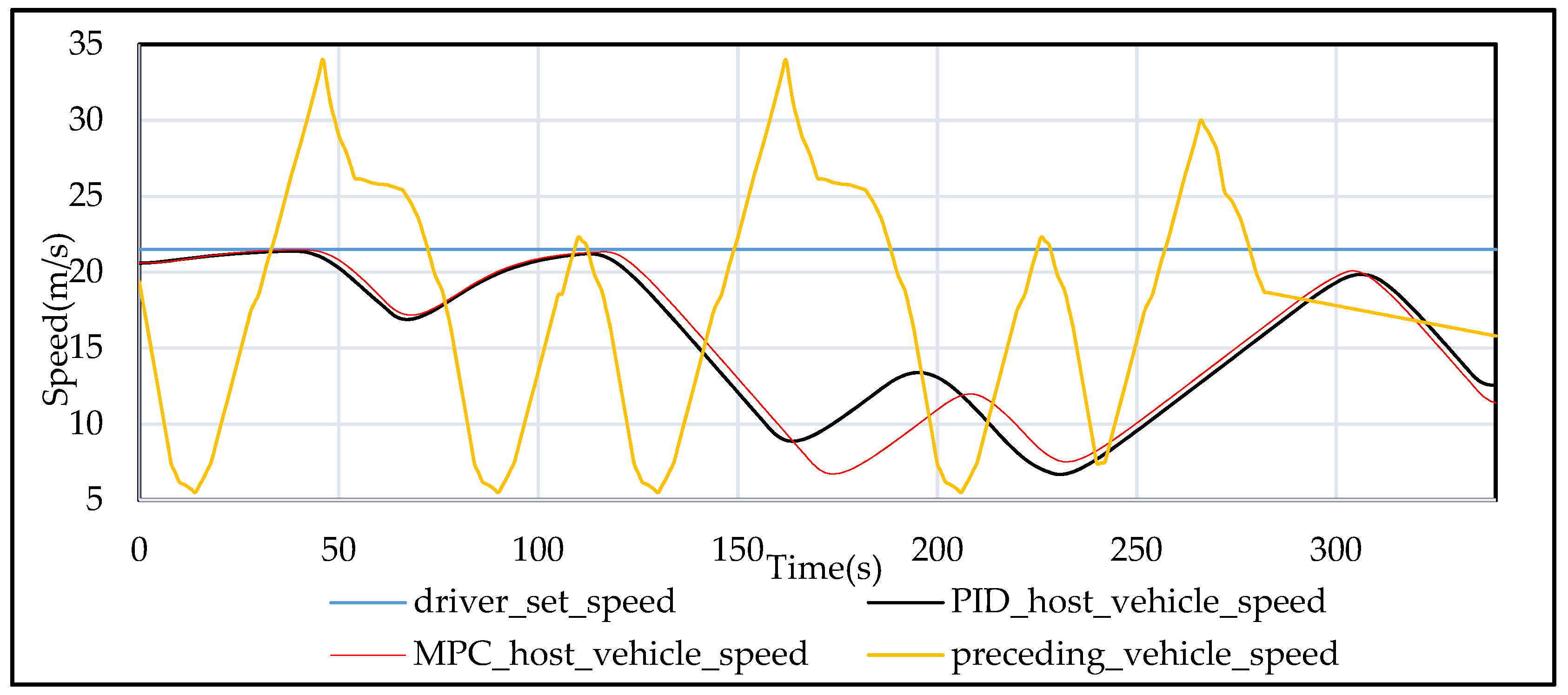
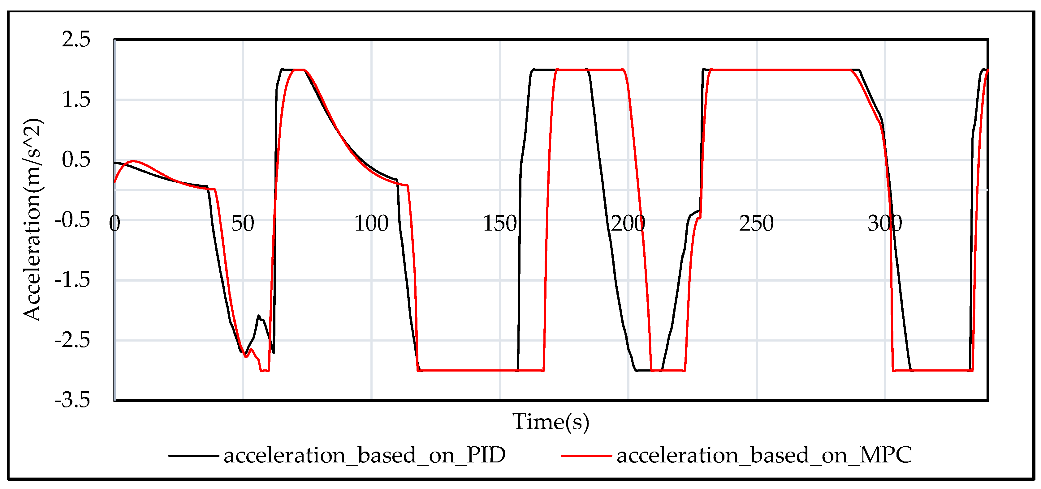
3. Results and Discussion

The simulation test bench is established to evaluate the performance of the proposed multiple objectives optimization strategy for the adaptive cruise control system. The simulation and comparison are conducted separately by two distinct control algorithms. The first one is the proposed MPC-based ACC system, considering the eco-driving assessment indicator fuel economy and other objectives, including driving comfortability, safety, and car-following. The other one is the ACC system based on the classic PID controller, which is only considering the car-following objective. An apparent difference between the PID controller and MPC controller is that the classic PID controller features in constant gains. In contrast, the MPC controller regulates the velocity of the host vehicle, while maintaining a strict safe distance constraint, which means that the MPC controller is capable of applying more aggressive maneuvers when the environment changes suddenly. The inter-distance from the host vehicle to the preceding vehicle is regulated strictly so that it is equal or greater than the critical minimum distance, which is regarded as the demand for driving safety. The magnitudes of acceleration and jerk are used to assess operating comfortability and fuel economy. The input to the emission and fuel consumption model is the speed profile data of host ACC-equipped vehicle, and the exhaust emission rate maps are plotted using instantaneous speed and acceleration data. Ultimately, the vehicle fuel economy is estimated.
Two typical simulation driving scenarios are defined and used in this study:
  • Scenario 1: Following a preceding vehicle with varying speed;
  • Scenario 2: Following the changing preceding vehicles with a cut in and cut out behaviors.
Generally, most integrated and complicated traffic scenes constitute the above two basic traffic scenarios. The related input parameters used in the simulation model are listed in Table 1.
The first scenario of tracking a preceding vehicle with varying speed is the most typical traffic scene in a real driving situation. The speed profile for the preceding vehicle is reasonably generated. From Figure 7, it is noted that the host vehicle’s speed responses to the predefined velocity of the preceding vehicle for both the PID-based ACC system and the MPC-based ACC system perform well. The cruise speed for the ACC system is set by the driver as 21.5 m / s . The driving comfortability assessment index, the acceleration, is presented in Figure 8, from which it can be observed that the MPC-based ACC system possesses a relatively smoother response than the PID-based ACC system. Figure 9 shows that both the PID-based and MPC-based ACC systems can follow the preceding vehicle actively without any accident, because the safe spacing is never exceeded the limit. Therefore, the performance of tracking and driving safety can be ensured for both two controllers. Table 2 shows the results of HC ,   CO ,   CO 2   and   NO X emissions for both models in Scenario 1. Figure 10 shows that, the MPC-based ACC system can achieve about 12% improvement in fuel economy in Scenario 1.
In scenario 2, which is about following the changing preceding vehicles with cut in and cut out behaviors, the ACC-equipped host vehicle operates along a predefined road section. At the outset, the host green vehicle follows a preceding red vehicle. Then, a yellow vehicle traveling on the neighboring lane cuts into the lane of the host vehicle, and becomes the newly preceding vehicle. After a period, this newly preceding yellow vehicle changes to another lane so that the original red one becomes the preceding vehicle again. The scenario concept is demonstrated in Figure 11. The proposed ACC system is required to make the reaction to the change in the preceding vehicle on the road. The initial velocity of the host vehicle is assumed to be 20.5 m / s . The simulation results of two control algorithms, ACC based on classic PID controller and ACC based on the proposed MPC controller, are shown in Figure 12, Figure 13, Figure 14 and Figure 15, and the results for the emissions are reported in Table 3.
As shown in Figure 14, the preceding vehicle is driving far ahead of the host vehicle in the former 120 s. So, the host vehicle accelerates during this period and reaches the driver set velocity, seen from Figure 11. From 120 to around 200 s, the vehicle driving on the neighboring lane cuts into the host vehicle lane, and becomes the newly preceding vehicle. The host vehicle operates at the driver set velocity during around 120 to 150 s, when the spacing between the host vehicle and the preceding vehicle is large. However, from 150 to 200 s, the spacing is reduced, and then the host vehicle decelerates its speed to maintain safe spacing from the preceding vehicle, which is shown in Figure 12. During 200 to 340 s, the preceding vehicle again changes its lane, and the original vehicle becomes the preceding vehicle again, which can be seen from Figure 14. At this time, the spacing between the two vehicles is large, so the host vehicle accelerates to reach the driver set velocity. According to Figure 13, the acceleration response of the MPC-based ACC system shows a smoother transient behavior indicating that the driving comfortability performs better for the MPC-based ACC system compared to the PID-based ACC system. Figure 15 represents the fuel economy for two controllers. The fuel economy of the PID-based ACC system finally stabilized at 8.2 L/100 km, and in contrast, the fuel economy of the MPC-based ACC system is finally maintained at 7.1 L/100 km, which means that an improvement of 13% in fuel is achieved in this driving scenario.
In summary, through the above analysis, the proposed MPC-based ACC system performs better driving comfortability in contrast with the classic PID-based ACC system. In terms of following and driving safety, both are guaranteed by two different controllers. As far as the performance of eco-driving is concerned, it is apparent that the MPC-based ACC system can reduce fuel consumption compared with the classic PID-based ACC system.
To justify the proposed MPC-based ACC system, the comparison between the proposed MPC-ACC system in this research and other standard models implemented on commercial production vehicles such as the PID-based ACC system and fuzzy logic control (FLC)-based ACC system are summarized and discussed. Under the standard ACC system, the host vehicle accelerates to the driver set velocity and cruises until it detects the preceding vehicle, and then it tracks the preceding vehicle, only considering the safe distance [40,41]. Whereas, the proposed MPC-based ACC system is easy to achieve precise and optimal control with future traveling information. It is capable of realizing the real-time multi-objective control, where the eco-driving, reducing fuel consumption, can be achieved by improving the fuel economy by 12–13%. Compared with the FLC-based ACC system [42], the proposed ACC system can achieve multiple objectives, including car-following, driving safety and comfortability, and fuel economy with fewer parameters to consider. However, the FLC-based ACC system generally yields nonoptimal control command in real driving conditions compared with the proposed MPC-based ACC system, which conducted an online optimization process to obtain an optimal control command.

4. Conclusions

In this study, an adaptive cruise control system is designed, based on the framework of model predictive control to optimize multiple objectives, including car-following, driving safety, comfortability, as well as the eco-driving. The vehicle dynamic model, the adaptive cruise control model, model predictive control framework, and instantaneous emission and fuel consumption model are proposed and analyzed. The performance of the proposed MPC-based ACC system is compared with the classic PID-based ACC system. Based on the above models, the simulation experiments are conducted in two typical and representative driving scenarios. The simulation results show that the new MPC-based ACC system performs as well as the classic PID-based ACC system, in terms of car following capability and driving safety. What is noteworthy is that the MPC-based ACC system achieves an improvement of 12–13% in fuel economy, in comparison with the classic PID-based ACC system. Furthermore, the driving comfortability is optimized by the proposed new ACC system. A prospective situation is that the proposed MPC-based ACC system will encourage more users to accept the adaptive cruise control system, as a result of better driving comfortability and fuel economy, and this research can lay the groundwork for developing a more intelligent autopilot system.

Author Contributions

Conceptualization: Z.N. and H.F., methodology, and investigation: Z.N., Writing—review, editing, and supervising: H.F. All authors have read and agreed to the published version of the manuscript.

Funding

This research was supported by the Kurata grant of the Hitachi Global Foundation.

Acknowledgments

The author wishes to thank the editor and the reviewers for their contributions on the paper.

Conflicts of Interest

The author declares no conflict of interest.

References

  1. Zhou, M.; Jin, H.; Wang, W. A review of vehicle fuel consumption models to evaluate eco-driving and eco-routing. Transp. Res. Part D Transp. Environ. 2016, 49, 203–218. [Google Scholar] [CrossRef]
  2. Saboohi, Y.; Farzeneh, H. Model for optimizing energy efficiency through controlling speed and gear ratio. Energy Effic. 2008, 1, 65–76. [Google Scholar] [CrossRef]
  3. Wang, Y.; Boggio-Marzet, A. Evaluation of Eco-Driving Training for Fuel Efficiency and Emissions Reduction According to Road Type. Sustainability 2018, 10, 3891. [Google Scholar] [CrossRef] [Green Version]
  4. Farzeneh, H.; Saboohi, Y. Evaluation of the optimal performance of passenger vehicle by integrated energy-environment-economic modeling. Int. J. Environ. Sci. Technol. 2007, 4, 189–196. [Google Scholar] [CrossRef] [Green Version]
  5. Kim, Y.; Lee, I.; Kang, S. Eco Assist Techniques through Real-time Monitoring of BEV Energy Usage Efficiency. Sensors 2015, 15, 14946–14959. [Google Scholar] [CrossRef] [PubMed]
  6. Jiménez, F.; Cabrera-Montiel, W.; Tapia-Fernández, S. System for Road Vehicle Energy Optimization Using Real Time Road and Traffic Information. Energies 2014, 7, 3576–3598. [Google Scholar] [CrossRef]
  7. Farzeneh, H.; Saboohi, Y. Software of passenger vehicle optimal work and energy recovery (POWER). Proceedings of Urban Transport XII: Urban Transport and the environment in the 21st Century, Prague, Czech Republic, 12–14 July 2006; Available online: https://www.researchgate.net/publication/271450637_Software_of_passenger_vehicle_optimal_work_and_energy_recovery_POWER (accessed on 2 June 2020).
  8. Ivens, T.; Spronkmans, S.; Roşca, B.; Wilkins, S. Model-Based Eco-Driving and Integrated Powertrain Control for (Hybrid) Electric Vehicles. World Electr. Veh. J. 2013, 6, 336–344. [Google Scholar] [CrossRef] [Green Version]
  9. Farzaneh, H.; Saboohi, Y. Model for analysis of energy flow from tank-to-wheel in a passenger vehicle. In Proceedings of the IEEE Vehicle Power and Propulsion Conference, Chicago, IL, USA, 7–9 September 2005. [Google Scholar]
  10. Gilbert, E.G. Vehicle cruise: Improved fuel economy by periodic control. Automatica 1976, 12, 159–166. [Google Scholar] [CrossRef] [Green Version]
  11. Chang, D.J.; Morlok, E.K. Vehicle Speed Profiles to Minimize Work and Fuel Consumption. J. Transp. Eng. 2005, 131, 173–182. [Google Scholar] [CrossRef]
  12. Schwarzkopf, A.; Leipnik, R. Control of highway vehicles for minimum fuel consumption over varying terrain. Transp. Res. 1977, 11, 279–286. [Google Scholar] [CrossRef]
  13. Manzie, C.; Watson, H.; Halgamuge, S.K. Fuel economy improvements for urban driving: Hybrid vs. intelligent vehicles. Transp. Res. Part C Emerg. Technol. 2007, 15, 1–16. [Google Scholar] [CrossRef]
  14. Khout, N.; Borrelli, F.; Hedrick, K. Intelligent traffic data and model predictive control to improve fuel economy. In Proceedings of the 12th IFAC Symposium on Control in Transportation Systems, Redondo Beach, CA, USA, 2–4 September 2009; Volume 42, pp. 155–160. [Google Scholar]
  15. Saboohi, Y.; Farzeneh, H. Model for developing an eco-driving strategy of a passenger vehicle based on the least fuel consumption. Appl. Energy 2009, 86, 1925–1932. [Google Scholar] [CrossRef]
  16. Ichihara, T.; Kumano, S.; Yamaguchi, D.; Sato, Y.; Suda, Y. Driver assistance system for eco-driving. In Proceedings of the 16th International Transport Systems World Congress, Stockholm, Sweden, 21–25 September 2009. [Google Scholar]
  17. Jenness, J.W.; Lerner, N.D.; Mazor, S.; Osberg, J.S.; Tefft, B.C. Use of Advanced In-Vehicle Technology By Young and Older Early Adopters Survey Results on Navigation Systems. Traffic Saf. 2008, 810, 917. [Google Scholar]
  18. Abdullah, R.; Hussain, A.; Warwick, K.; Zayed, A. Autonomous intelligent cruise control using a novel multiple-controller framework incorporating fuzzy-logic-based switching and tuning. Neurocomputing 2008, 71, 2727–2741. [Google Scholar] [CrossRef]
  19. Ganji, B.; Kouzani, A.Z.; Khoo, S.Y.; Shams-Zahraei, M. Adaptive cruise control of a HEV using sliding mode control. Expert Syst. Appl. 2014, 41, 607–615. [Google Scholar] [CrossRef]
  20. Desjardins, C.; Chaib-Draa, B. Cooperative Adaptive Cruise Control: A Reinforcement Learning Approach. IEEE Trans. Intell. Transp. Syst. 2011, 12, 1248–1260. [Google Scholar] [CrossRef]
  21. Kamal, A.S.; Mukai, M.; Murata, J.; Kawabe, T. Model Predictive Control of Vehicles on Urban Roads for Improved Fuel Economy. IEEE Trans. Control Syst. Technol. 2012, 21, 831–841. [Google Scholar] [CrossRef]
  22. Martin, T.; Arne, K. Traffic Flow Dynamics: Data, Models and Simulation; Springer: Berlin, Germany, 2013. [Google Scholar] [CrossRef]
  23. Corona, D.; Lazar, M.; De Schutter, B. A hybrid MPC approach to the design of a Smart adaptive cruise controller. In Proceedings of the IEEE International Symposium on Computer Aided Control System Design, San Francisco, CA, USA, 13–15 April 2009. [Google Scholar]
  24. Naus, G.; Ploeg, J.; Van De Molengraft, R.; Steinbuch, M. Explicit MPC design and performance-based tuning of an Adaptive Cruise Control Stop-&-Go. In Proceedings of the 2008 IEEE Intelligent Vehicles Symposium, Eindhoven, The Netherlands, 4–6 June 2008; pp. 434–439. [Google Scholar] [CrossRef]
  25. Dang, R.N.; Chaoche, H.; Zhang, K.Q. ACC of electric vehicle with coordination control of fuel economy and tracking safety. Proceeding of the 2012 IEEE Intelligent Vehicles Symposium, Alcala de Henares, Spain, 3–7 June 2012; Available online: https://ieeexplore.ieee.org/abstract/document/6232121 (accessed on 8 June 2020).
  26. Gillespie, T.D. Fundamentals of vehicle dynamics; SAE Int.: Warrendale, PA, US., 1992; pp. 8–20. [Google Scholar]
  27. Rajamani, R.; Zhu, C. Semi-autonomous adaptive cruise control systems. IEEE Trans. Veh. Technol. 2002, 51, 1186–1192. [Google Scholar] [CrossRef]
  28. Bageshwar, V.; Garrard, W.; Rajamani, R. Model Predictive Control of Transitional Maneuvers for Adaptive Cruise Control Vehicles. IEEE Trans. Veh. Technol. 2004, 53, 1573–1585. [Google Scholar] [CrossRef]
  29. Zhou, J.; Peng, H. Range Policy of Adaptive Cruise Control Vehicles for Improved Flow Stability and String Stability. IEEE Trans. Intell. Transp. Syst. 2005, 6, 229–237. [Google Scholar] [CrossRef]
  30. Sheng, Z.; Xiangtao, Z. Model-predictive for pure electric vehicle during a vehicle-following process. Math. Probl. Eng. 2019, 2019, 15. [Google Scholar]
  31. Martines, J.J.; Canudas-de-Wit, C. A safe longitudinal control for adaptive cruise control and stop-and-go scenarios. IEEE Trans. Control Syst. Technol. 2007, 15, 246–258. [Google Scholar] [CrossRef]
  32. Luo, L.-H.; Liu, H.; Li, P.; Wang, H. Model predictive control for adaptive cruise control with multi-objectives: Comfort, fuel-economy, safety and car-following. J. Zhejiang Univ. A 2010, 11, 191–201. [Google Scholar] [CrossRef]
  33. Moon, S.; Yi, K. Human driving data-based design of a vehicle adaptive cruise control algorithm. Veh. Syst. Dyn. 2008, 46, 661–690. [Google Scholar] [CrossRef]
  34. Sun, N.; Yang, T.; Fang, Y.; Wu, Y.; Chen, H. Transportation Control of Double-Pendulum Cranes With a Nonlinear Quasi-PID Scheme: Design and Experiments. IEEE Trans. Syst. Man. Cybern. Syst. 2019, 49, 1408–1418. [Google Scholar] [CrossRef]
  35. Boyd, S.; Vandenberghe, L. Convex Optimization; Cambridge University: New York, NY, USA, 2004; pp. 561–562. [Google Scholar]
  36. Joumard, R.; Jost, P.; Hickman, J.; Hassel, D. Hot passenger car emissions modelling as a function of instantaneous speed and acceleration. Sci. Total Environ. 1995, 169, 167–174. [Google Scholar] [CrossRef]
  37. Sturm, P.; Almbauer, R.; Sudy, C.; Pucher, K. Application of Computational Methods for the Determination of Traffic Emissions. J. Air Waste Manag. Assoc. 1997, 47, 1204–1210. [Google Scholar] [CrossRef]
  38. Boulter, P.G.; McCrae, L.S.; Barlow, T.J. A Review of Instantaneous Emission Models for Road Vehicles; TRL Limited: Wokingham, UK, 2006. [Google Scholar]
  39. Argonne National Library. Energy System Division: Downloadable Dynamometer Database; Argonne National Library: Lemont, IL, USA, 2015. Available online: https://www.anl.gov/es/downloadable-dynamometer-database (accessed on 20 March 2015).
  40. Güvenç, L.; Uygan, I.M.C.; Kahraman, K.; Karaahmetoglu, R.; Altay, I.; Senturk, M.; Emirler, M.T.; Karci, A.E.H.; Güvenç, B.A.; Altuğ, E.; et al. Cooperative Adaptive Cruise Control Implementation of Team Mekar at the Grand Cooperative Driving Challenge. IEEE Trans. Intell. Transp. Syst. 2012, 13, 1062–1074. [Google Scholar] [CrossRef]
  41. Nieuwenhuijze, M.R.I.; Van Keulen, T.; Oncu, S.; Bonsen, B.; Nijmeijer, H. Cooperative Driving With a Heavy-Duty Truck in Mixed Traffic: Experimental Results. IEEE Trans. Intell. Transp. Syst. 2012, 13, 1026–1032. [Google Scholar] [CrossRef]
  42. Naranjo, J.; Gonzalez, C.; Reviejo, J.; Garcia, R.; De Pedro, T. Adaptive fuzzy control for inter-vehicle gap keeping. IEEE Trans. Intell. Transp. Syst. 2003, 4, 132–142. [Google Scholar] [CrossRef] [Green Version]
Figure 1. The kinematic relationship.
Applsci 10 05271 g001
Figure 2. The dynamic bicycle model diagram.
Applsci 10 05271 g002
Figure 3. The framework of the model predictive control (MPC)-based adaptive cruise control (ACC) system.
Applsci 10 05271 g003
Figure 4. Schematic of overall data transfer.
Applsci 10 05271 g004
Figure 5. Simulation test bench.
Applsci 10 05271 g005
Figure 6. Structure of proportional-integral-derivative (PID) controller for ACC system.
Applsci 10 05271 g006
Figure 7. Speed response in scenario 1.
Applsci 10 05271 g007
Figure 8. Acceleration response in scenario 1.
Applsci 10 05271 g008
Figure 9. Spacing response in scenario 1.
Applsci 10 05271 g009
Figure 10. Fuel economy in scenario 1.
Applsci 10 05271 g010
Figure 11. Concept demonstration of scenario 2.
Applsci 10 05271 g011
Figure 12. Speed response in scenario 2.
Applsci 10 05271 g012
Figure 13. Acceleration response in scenario 2.
Applsci 10 05271 g013
Figure 14. Spacing response in scenario 2.
Applsci 10 05271 g014
Figure 15. Fuel economy in scenario 2.
Applsci 10 05271 g015
Table 1. Input parameters used in the simulation.
SymbolValuesUnitsSymbolValuesUnits
T s 0.1 s p 16
R 760 m c h 5
m 1575 kg v min 0 m / s
I z 2875 m · N · s 2 v max 50 m / s
l f 1.2 m a min 3 m / s 2
l r 1.6 m a max 2 m / s 2
C f 19,000 N / rad j e r k min 3 m / s 3
C r 33,000 N / rad j e r k max 3 m / s 3
τ 0.5 s c min 3 m / s 2
θ c 1.5 s c max 2 m / s 2
x 0 7 m ρ δ i , ρ v i , ρ a i , ρ j i 0.94
x m i n 5 m T 340 s
α d i a g { 1 , 10 , 1 , 1 } β 1
v e r r _ g a i n 0.5 x e r r _ g a i n 0.2
v r e l _ e r r _ g a i n 0.4 y a w e r r _ g a i n 2
P p r o p o r t i o n a l _ g a i n 0.2 I i n t e g r a l g a i n   0.1
Table 2. Emissions results in Scenario 1.
HC ( g / km ) C O ( g / km ) C O 2 ( g / km ) N O X ( g / km )
PID-based ACC1.404.36434.603.48
MPC-based ACC1.304.18429.803.34
Improvement (%)7.144.121.104.02
Table 3. Emissions results in Scenario 2.
HC ( g / km ) CO ( g / km ) CO 2 ( g / km ) NO X ( g / km )
PID-based ACC1.414.65364.833.26
MPC-based ACC1.153.86308.812.88
Improvement (%)18.7016.9915.3511.65

