Article

Natural Frequency Characteristics of the Beam with Different Cross Sections Considering the Shear Deformation Induced Rotary Inertia

1
Key Laboratory of Concrete and Prestressed Concrete Structure of Ministry of Education, Southeast University, Nanjing 210096, China
2
Research Institute of Structural Engineering and Disaster Reduction, College of Civil Engineering, Tongji University, Shanghai 200092, China
3
College of Civil Engineering & Mechanics, Xiangtan University, Xiangtan 411105, China
4
Department of Architecture, Tohoku Institute of Technology, Sendai, Miyagi 982-8577, Japan
*
Authors to whom correspondence should be addressed.
Appl. Sci. 2020, 10(15), 5245; https://doi.org/10.3390/app10155245
Submission received: 16 June 2020 / Revised: 14 July 2020 / Accepted: 23 July 2020 / Published: 29 July 2020
(This article belongs to the Section Civil Engineering)

Abstract

:
Based on the classical Timoshenko beam theory, the rotary inertia caused by shear deformation is further considered and then the equation of motion of the Timoshenko beam theory is modified. The dynamic characteristics of this new model, named the modified Timoshenko beam, have been discussed, and the distortion of natural frequencies of Timoshenko beam is improved, especially at high-frequency bands. The effects of different cross-sectional types on natural frequencies of the modified Timoshenko beam are studied, and corresponding simulations have been conducted. The results demonstrate that the modified Timoshenko beam can successfully be applied to all beams of three given cross sections, i.e., rectangular, rectangular hollow, and circular cross sections, subjected to different boundary conditions. The consequence verifies the validity and necessity of the modification.

1. Introduction

Research on transverse vibration of the beam can date back to the 18th century. Leonhard Euler and Jacob Bernoulli presented the Bernoulli–Euler beam theory based on famous classical assumptions [1]. It was believed that the bending effect is the most significant factor for a transversely vibrating beam. Later, this beam model was gradually improved by Rayleigh [2], who took the effect of rotary inertia caused by the flexural deformation into account. The Rayleigh beam theory partially revises the distortion of natural frequencies calculated by the Bernoulli–Euler beam theory. Despite this modification, the natural frequencies remain distorted and are rather severe when a beam is not slim enough. Afterwards, the shear model took the shear deformation into account based on the Bernoulli–Euler model. It is recognized that the shear stress is evenly distributed along the beam height without considering the rotary inertia caused by the bending effect. In contrast, the pure shear model [3] only includes the shear deformation but excludes an important factor, the bending effect. The difference between them should be noted. Considering shear deformation based on the Bernoulli–Euler beam, the precision estimation of natural frequencies increases conspicuously. The Timoshenko beam theory [4,5] was proposed by Timoshenko, who considered the effect of shear deformation and the rotary inertia caused by the flexural deformation. Accuracy of the natural frequencies of the Timoshenko beam model is significantly improved, and therefore, it is applied widely. Many researches have been devoted since the Timoshenko beam theories were presented. Traill-Nash and Collar [6] finished a complete study where the derivation process for the four beam models with four various boundary conditions was described in detail in 1953. The orthogonality conditions of the Timoshenko beam were presented by Dolph [7], who also solved the initial and boundary-value problem of the Timoshenko beam. Herrmann [8] derived the orthogonality conditions of the Timoshenko beam with the modal expansion method and provided an analytical solution of the forced Timoshenko beam in 1955. Boley and Chao [9] investigated the dynamic response of the semi-infinite beams under four given boundary conditions using the Laplace inverse method. Huang [10] derived partial differential equations for flexural vibrations of six common types of simple, finite beams. Reismann and Pawlik [11] put forward a solution to the dynamic response of Timoshenko beams with the given initial conditions and external forces using the eigenfunction expansion method. Since the classical theory of the Timoshenko beam was applied to scientific research and practical engineering, more controversies followed. The major point of contention is the second spectrum of the Timoshenko beam. Traill-Nash and Collar pointed out the possibility of a second spectrum of the Timoshenko beam in 1953, and many efforts have been devoted to this study. Anderson [12] and Dolph analyzed the vibration characteristics of the simply supported Timoshenko beam, and two sets of independent spectrum curves of the Timoshenko beam were proposed. Downs [13] also claimed the existence of a second spectrum using the dynamic discrete element method. However, there are still many scholars who hold opposite opinions. Levinson and Cooke [14] used relatively elementary analysis, showing that there is no second spectrum for a Timoshenko beam with any boundary conditions. Abbas and Thomas [3,15] believed the nonexistence of the second spectrum except for a hinged-hinged beam by using the finite element method. N.G Stephen [16,17,18] compared the second spectrum with a solution derived from the plane stress elastic theory and found that there is no relationship between them as well as a physical meaning of the second spectrum. In 2006, he finished a further appraisal on the second spectrum of the Timoshenko beam and thought it should be neglected. Other than the uniform beam, Murin et al. [19] extended the Timoshenko beam to the multilayered functionally graded material (FGM) beam, derived a fourth-order differential equation of FGM beam deflection with variation of material properties, and considered the shear force deformation effect as well.
It is recognized that the Timoshenko beam is a tremendous advance for deep beams and for higher-order frequencies where shear deformation and rotary inertia cannot be neglected. In spite of this major improvement, the calculation error of high-frequency response is still unsatisfactory. Following Timoshenko, Chen and Wan [20,21,22] first introduced the rotary inertia caused by shear deformation to the Timoshenko beam, and the motion equation of the beam was then derived. After the new model, which is named the modified Timoshenko beam in this paper, was presented, more detailed knowledge about the wave characters and vibration characters of the modified Timoshenko beam were obtained. It can be found that, even though the effect of such a modification is small when the frequency is low, it becomes evident when the frequency is much high, which is very important for the dynamic transient response analysis where high frequencies are more dominant than the lower ones [20]. Furthermore, they also demonstrated that only one frequency spectrum exists, hence the debate on how many frequency spectrums on earth for the deep beam may be settled. Thus, in this research, effects of the cross-sectional types on the modified Timoshenko beam are further discussed by numerical simulations. The results demonstrate the validity of the modified Timoshenko beam with different cross-sectional forms, which also verifies the necessity of the modification.

2. Modification of the Timoshenko Beam Model

In this section, basic information of the modified Timoshenko beam is presented, including the equation of the motion and the equation of the natural frequencies under three end conditions.

2.1. Equation of Motion for Modified Timoshenko Beam

For a beam, it is assumed as follows for the purpose of simplicity:
  • The motion of the beam is only restricted in the x–y plane with a small displacement in the y dimension.
  • During the deformation, the cross section still sticks to the planer assumption with a symmetric axis in the y direction.
  • Flexural deformation, shear deformation, and the rotary inertia they caused are all concerned.
  • Lateral shear stress is distributed uniformly along the height of the beam.
Figure 1 shows deformation of the modified Timoshenko beam and the corresponding cross section.
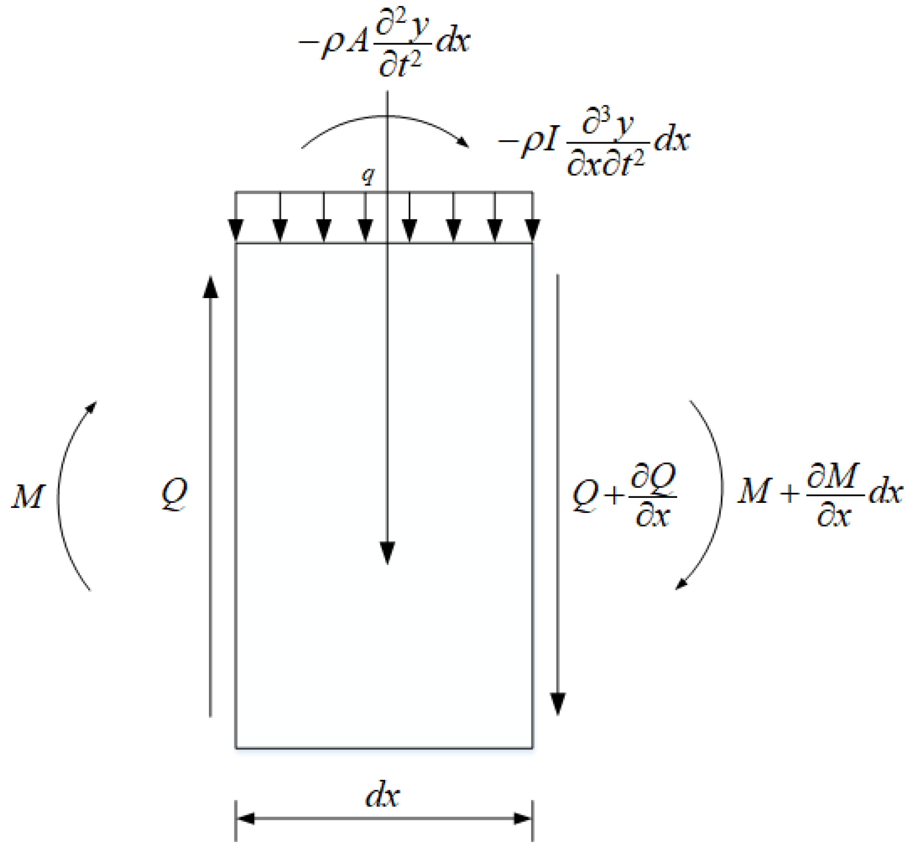
Figure 2 shows the lateral vibrations of a beam in the x–y plane due to lateral load. As is shown in the figure, the force equilibrium diagram for a differential element, including the internal force and the inertial force of bending moment direction and vertical direction, is presented. In this paper, shear force Q and bending moment M applies to the sign conventions in a beam. The inertia forces are ρ A 2 y t 2 in the y direction and ρ I 3 y x t 2 in rotational direction. The total slope θ consists of two parts: φ represents the bending slope, and β represents the slope induced by shear deformation.
The equation of motion for the Timoshenko beam is expressed as follows:
E I 4 y x 4 ( q ρ A 2 y t 2 ) ρ I 4 y x 2 t 2 + E I A G μ 2 x 2 ( q ρ A 2 y t 2 ) ρ I A G μ 2 t 2 ( q ρ A 2 y t 2 ) = 0  
where A represents the area of section, I represents the moment of inertia, G represents the shear modulus, ρ represents the material density, x represents the horizontal coordinates, y represents the transverse displacement, and t represents the time.
When the shear deformation-induced rotary inertia is considered, the equation of motion for the modified Timoshenko beam can be expressed as follows [21]:
E I 4 y x 4 ( q ρ A 2 y t 2 ) ρ I 4 y x 2 t 2 + E I A G μ 2 x 2 ( q ρ A 2 y t 2 ) = 0  
Compare Equations (1) and (2), we will note that the last term on the left side of Equation (1), ρ I A G μ 2 t 2 ( q ρ A 2 y t 2 ) , is due to the neglect of rotary inertia caused by the shear deformation.

2.2. Solution to Natural Frequencies under Different Boundary Conditions

Considering the complexity of the wave equation, we adopt the model solution and variable separation method to solve the vibration problems of the modified Timoshenko beam. Afterwards, the equation of natural frequencies for different boundary conditions was derived.
As for free vibration, q = 0 and, thus, we can obtain the following:
A G μ ( y x φ ) = E I 2 φ x 2 + ρ I 3 y x t 2
A G μ ( 2 y x 2 φ x ) = ρ A 2 y t 2
which denotes the basic equation of motion for a modified Timoshenko beam,
Let the following statement be true:
y ( x , t ) = Y ( x ) T ( t )
Substitute the above equation into Equation (2):
a 2 Y ( 4 ) ( x ) b 2 Y n ( x ) Y ( x ) = T ( t ) ¨ T ( t ) = ω 2  
where
a = E I ρ A
b = I A ( 1 + E G μ )
Set the following:
Y ( x ) = e λ x
Substitute Equation (9) into Equation (6):
a 2 λ 4 + b 2 ω 2 λ 2 ω 2 = 0
Solving Equation (10) will obtain four solutions:
λ 1 , 2 = ± b 2 ω 2 + b 4 ω 4 + 4 a 2 ω 2 2 a 2
λ 3 , 4 = ± b 2 ω 2 + b 4 ω 4 + 4 a 2 ω 2 2 a 2
Let the following be true:
g 1 = b 2 ω 2 + b 4 ω 4 + 4 a 2 ω 2 2 a 2
g 2 = b 2 ω 2 + b 4 ω 4 + 4 a 2 ω 2 2 a 2
g 3 = g 1 ( 1 + ρ b 2 ω 2 G μ ) + E r g 2 G μ g 1 3
g 4 = g 2 ( 1 + ρ b 2 ω 2 G μ ) + E r g 2 G μ g 2 3
From Equation (9), the general solution to the mode function for lateral vibration Y ( x ) is as follows:
Y ( x ) = c 1 e g 1 x + c 2 e g 1 x + c 3 e i g 2 x + c 4 e i g 2 x
Alternatively, it can be expressed as follows:
Y ( x ) = c 1 c o s h g 1 x + c 2 s i n h g 1 x + c 3 c o s h g 2 x + c 4 s i n h g 2 x
where c 1 , c 2 ,   c 3 , a n d   c 4 are coefficients.
Based on the above 18 equations, the natural characteristics for a Timoshenko beam can be derived.
For a hinged-hinged beam, the following equations can be derived from its boundary conditions:
c 1 + c 3 = 0
c 1 ( g 1 2 + ρ ω 2 G μ ) + c 3 ( ρ ω 2 G μ g 2 2 ) = 0
c 1 c o s h g 1 L + c 2 s i n h g 1 L + c 3 c o s g 2 L + c 4 s i n g 2 L = 0
c 1 ( g 1 2 + ρ ω 2 G μ ) c o s h g 1 L + c 2 ( g 1 2 + ρ ω 2 G μ ) s i n h g 1 L + c 3 ( ρ ω 2 G μ g 2 2 ) c o s g 2 L + c 4 ( ρ ω 2 G μ g 2 2 ) s i n g 2 L = 0
Thus, we can derive the equation for natural frequency:
s i n g 2 L = 0
Denote Equation (23) as follows:
f 1 ( ω ) = 0
From the above equation, natural frequencies for a hinged-hinged beam will be easily obtained.
For a clamped-clamped beam, we have the following:
c 1 + c 3 = 0
c 1 c o s h g 1 L + c 2 s i n h g 1 L + c 3 c o s g 2 L + c 4 s i n g 2 L = 0
c 2 g 3 + c 4 g 4 = 0
c 1 g 3 s i n h g 1 L + c 2 g 3 c o s h g 1 L + c 3 ( g 4 ) s i n g 2 L + c 4 g 4 c o s g 2 L = 0
For a dynamic problem, coefficients c 1 ,   c 2 ,   c 3 ,   a n d   c 4   cannot be all zeroes; otherwise, it becomes a static problem. Thus, the equation of the natural frequency can be expressed as follows:
| 1 0 1 0 cos h g 1 L sin h g 1 L cos g 2 L sin g 1 L 0 g 3 0 g 3 g 3 sin h g 1 L g 3 cos h g 1 L ( g 4 ) sin g 2 L g 4 cos g 2 L | = 0
Denote Equation (29) as follows:
f 2 ( ω ) = 0
where f 2 ( ω ) is the determinant of Equation (29) and frequency ω is de facto the eigenvalue of the corresponding matrix of the determinant. Name f 2 ( ω ) = 0 the frequency polynomial for a clamped-clamped beam, and every zero of the polynomial is namely every order of natural frequency for the beam. After expansion and simplification of the determinant, we will obtain the following equation:
f 2 ( ω ) = 2 g 3 g 4 + 2 g 3 g 4 c o s ( g 2 L ) c o s h ( g 1 L ) ( g 3 2 g 4 2 ) s i n ( g 2 L ) s i n h ( g 1 L )
from which natural frequencies of a clamped-clamped beam can be calculated.
For a clamped-free beam, we have the following:
c 1 g 1 g 3 c 3 g 2 g 4 = 0
c 2 ( g 3 g 1 ) + c 4 ( g 4 g 2 ) = 0
c 1 c o s h g 1 L + c 2 s i n h g 1 L + c 3 c o s g 2 L + c 4 s i n g 2 L = 0
c 1 g 3 s i n h g 1 L + c 2 g 3 c o s h g 1 L + c 3 ( g 4 ) s i n g 2 L + c 4 g 4 c o s g 2 L = 0
Since coefficients c 1 ,   c 2 ,   c 3 ,   a n d   c 4   are not all zeroes, the equation of the natural frequency can then be expressed as follows:
| g 1 g 3 0 g 2 g 4 0 0 g 3 g 1 0 g 4 g 2 cos h g 1 L sin h g 1 L cos g 2 L sin g 1 L g 3 sin h g 1 L g 3 cos h g 1 L ( g 4 ) sin g 2 L g 4 cos g 2 L | = 0
Denote Equation (36) as follows:
f 3 ( ω ) = 0
After expansion and simplification of the determinant, we will obtain the following equation:
f 3 ( ω ) = ( g 2 + g 4 ) g 1 g 3 2 ( cos ( g 2 L ) ) cosh ( g 1 L ) g 1 g 3 g 4 sin ( g 2 L ) sinh ( g 1 L ) g 2 g 3 g 4 cos h 2 ( g 1 L ) + g 2 g 3 g 4 sin h 2 ( g 1 L ) + ( g 1 + g 3 ) g 1 g 3 g 4 ( cos 2 ( g 2 L ) ) + g 1 g 3 g 4 sin 2 ( g 2 L ) g 2 g 3 g 4 sin ( g 2 L ) sinh ( g 2 L ) + g 2 g 4 2 cos ( g 2 L ) cosh ( g 1 L )
Similar to the clamped-clamped beam, name f 3 ( ω ) = 0 the frequency polynomial for clamped-free beam, and every zero of the polynomial is every order of natural frequency for the beam. The natural frequencies of the clamped-free beam will also be obtained through the equation.

3. Effect of the Cross-Sectional Types on Natural Frequencies

In this section, the top 20 orders of natural frequencies of the Bernoulli–Euler beam, the Rayleigh beam, the shear beam, the Timoshenko beam, and the modified Timoshenko beam are calculated and compared. From the comparisons, the natural frequencies of three section types change with regularity under different length and boundary conditions. The key point of the modified Timoshenko beam is its solution to the overestimation of natural frequencies, and the phenomenon is more obvious when the beam tends to be non-slender.
To establish the simulation model, the parameters of the beam are set as follows:
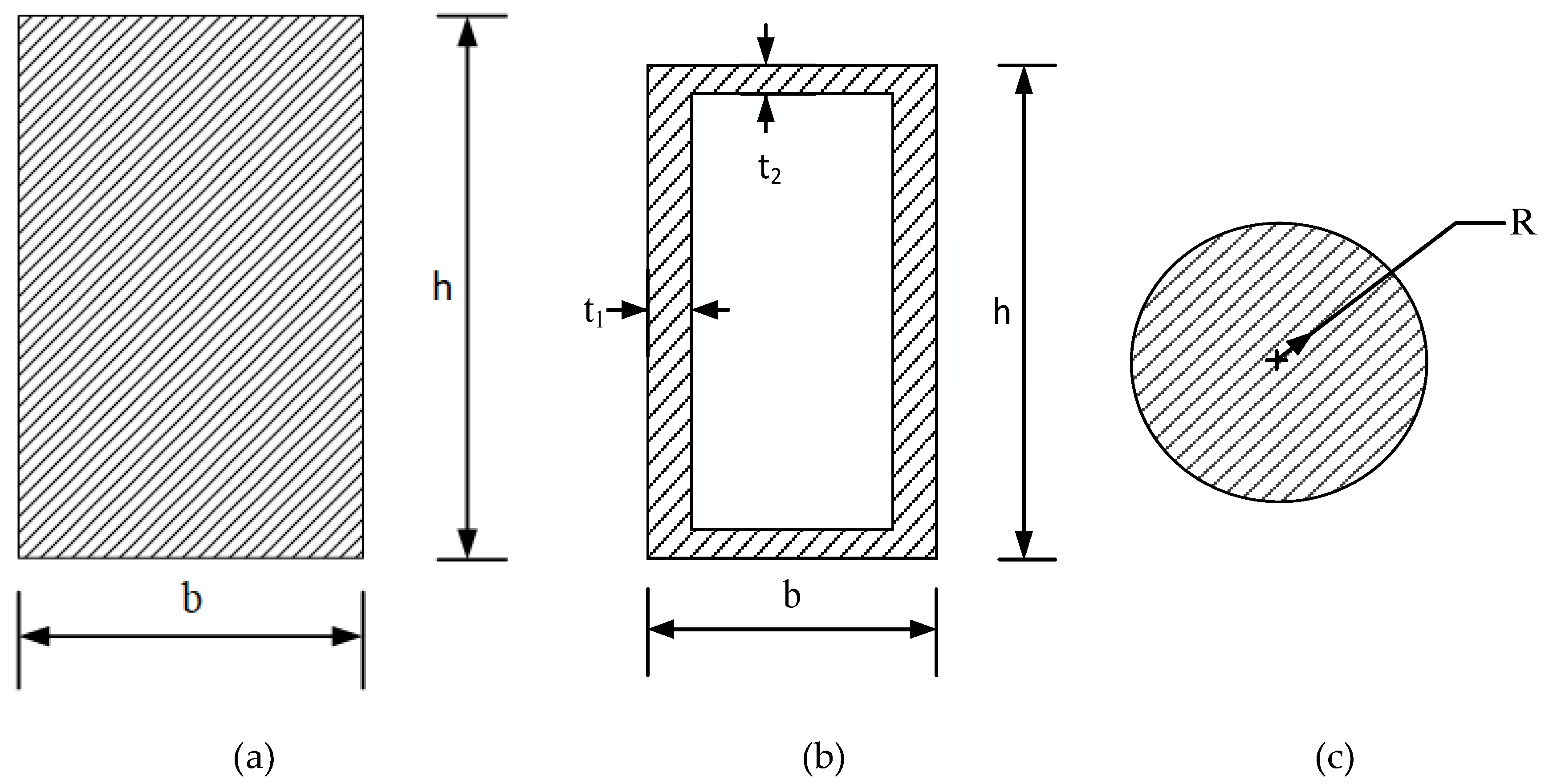
Elastic modulus, E = 210 × 10 9 P a ; Poisson’s ratio, ν = 0.3 ; shear modulus, G = E 2 ( 1 + ν ) ; mass density, ρ = 7850   k g · m 3 ; and shear coefficient, μ = 10 ( 1 + ν ) 12 + 11 ν . Three lengths of the beam, i.e., L = 8   m ,   L = 4   m ,   a n d   L = 2   m , are used to study the frequency effect for different slenderness ratios. Beams with three cross sections are considered and studied, with their section parameters as follows:
(1)
Rectangular section beam: Width:   b = 0.25   m , height:   h = 0.5   m .
(2)
Rectangular hollow section beam: Width: b = 0.25   m , height: h = 0.5   m , web thickness: t 1 = 0.04   m , and flange plate thickness:   t 2 = 0.02   m .
(3)
Circular section beam: Radius: R = 0.4   m .
The above section outlines are shown as Figure 3.

3.1. Rectangular Section Beam

3.1.1. Hinged-Hinged

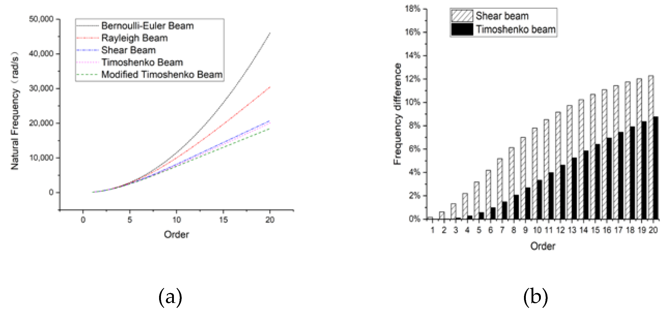
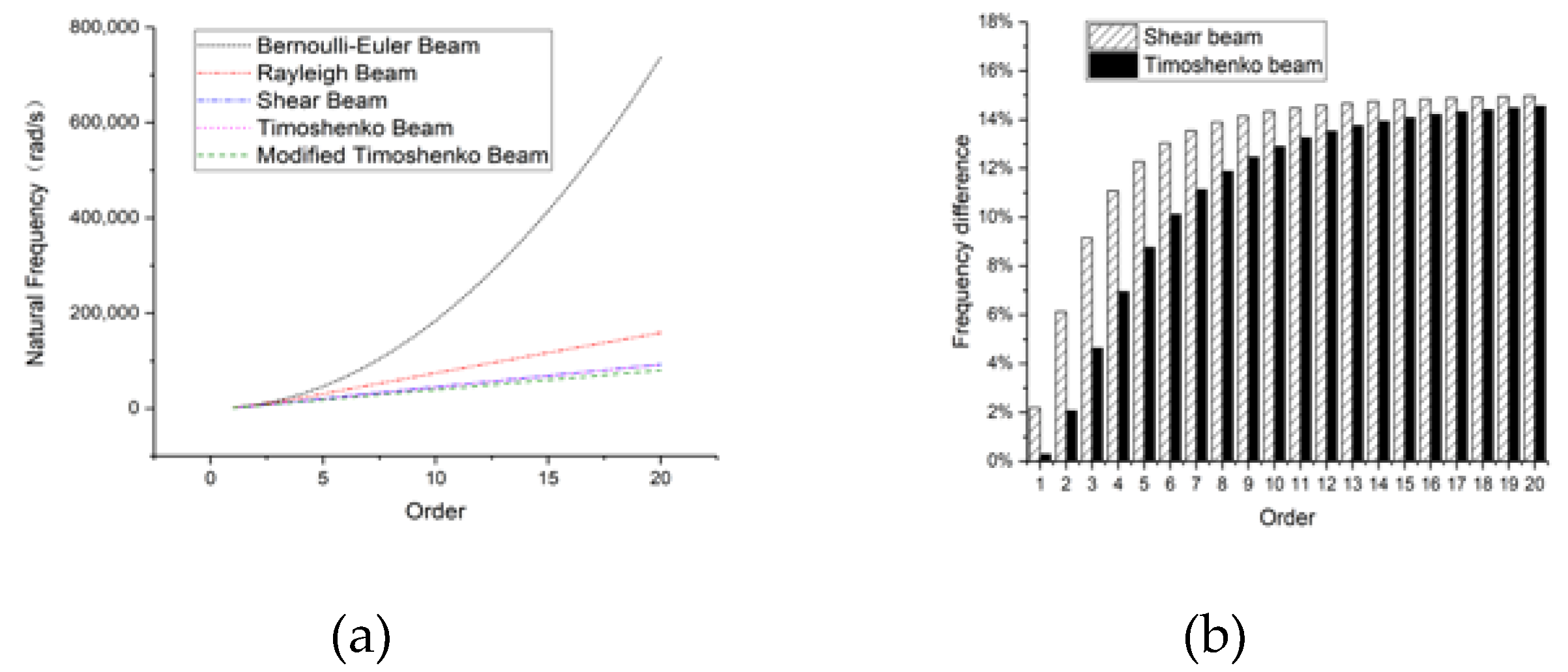
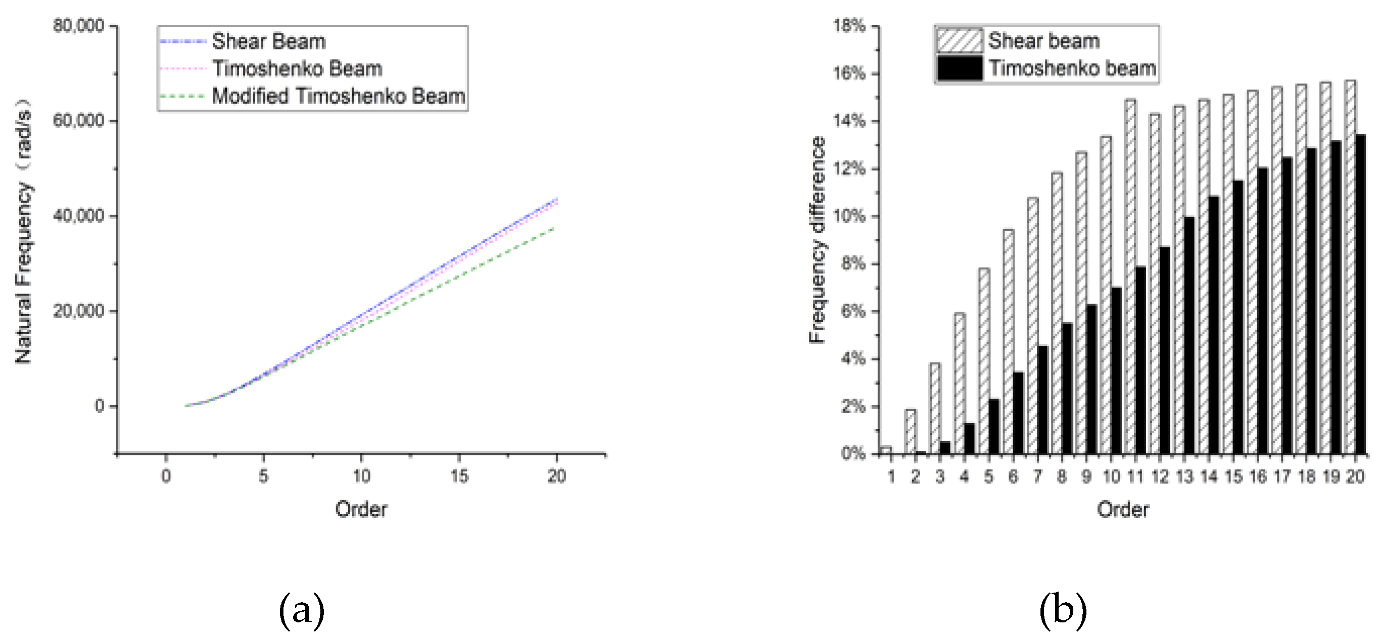
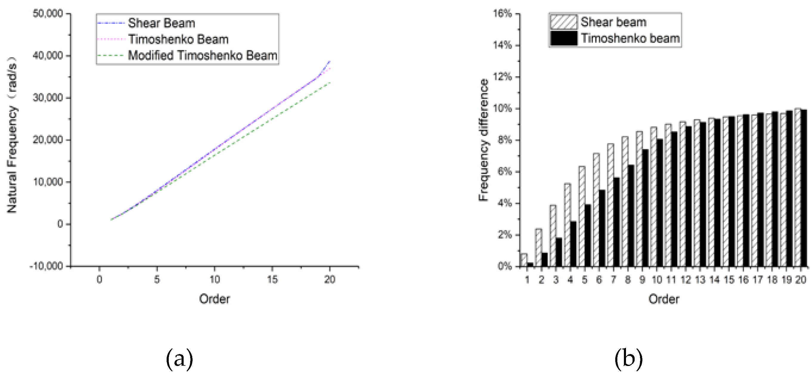
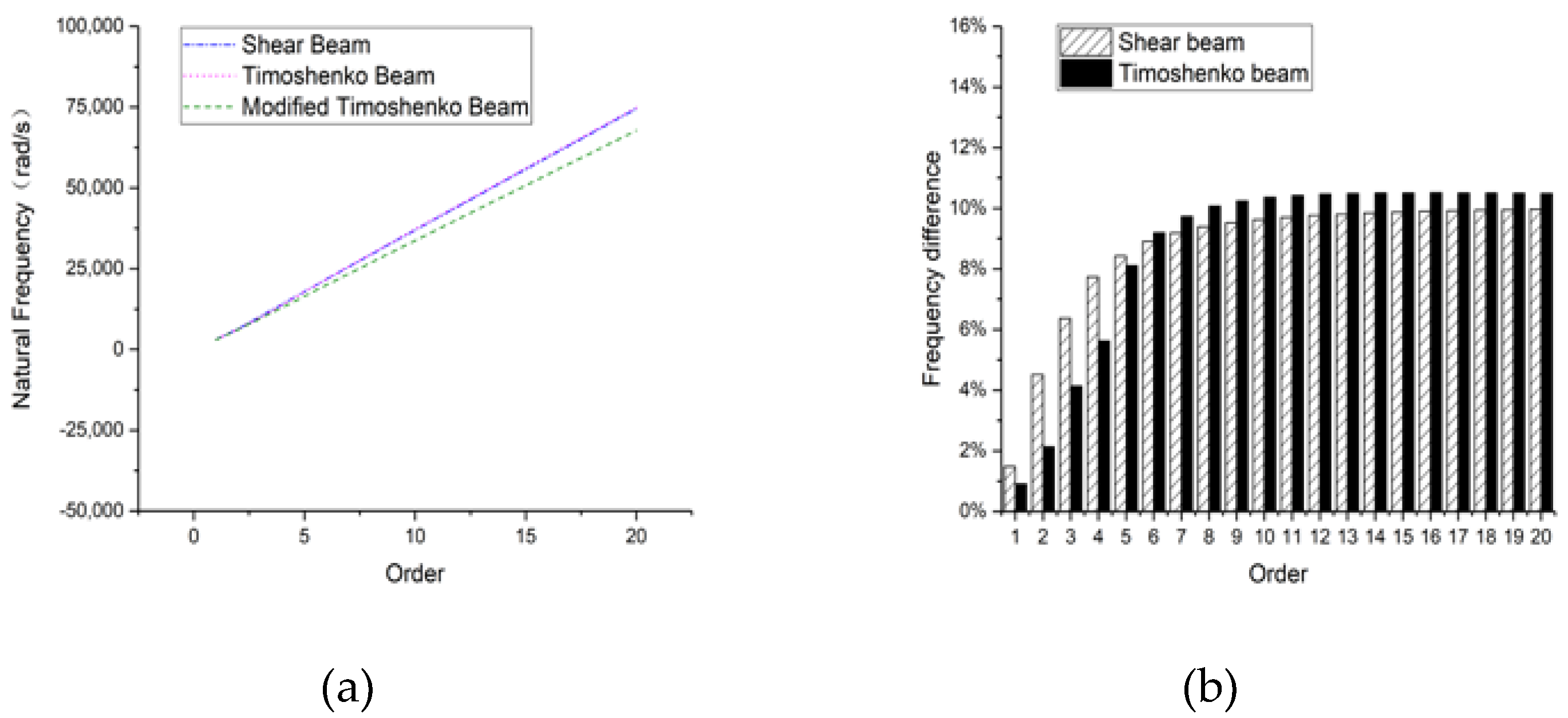
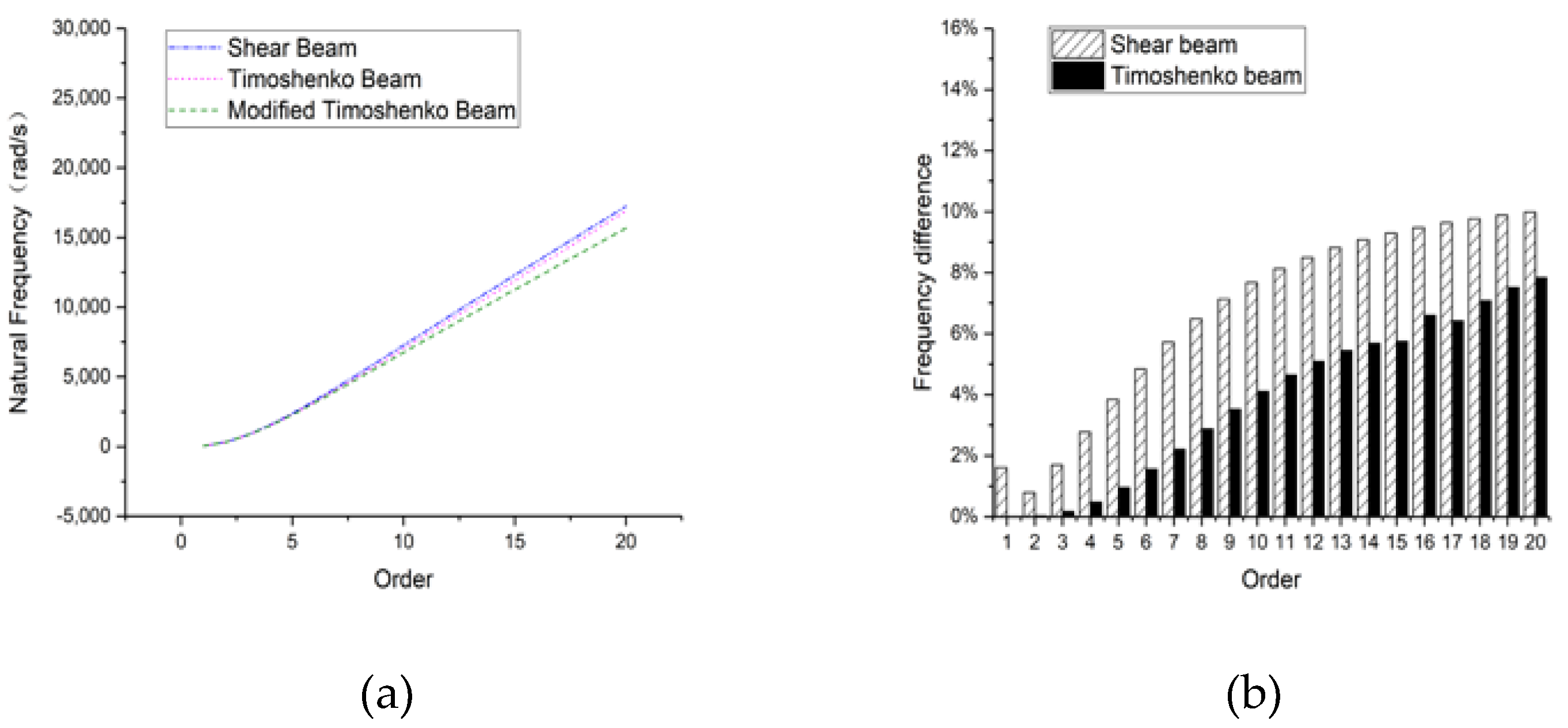
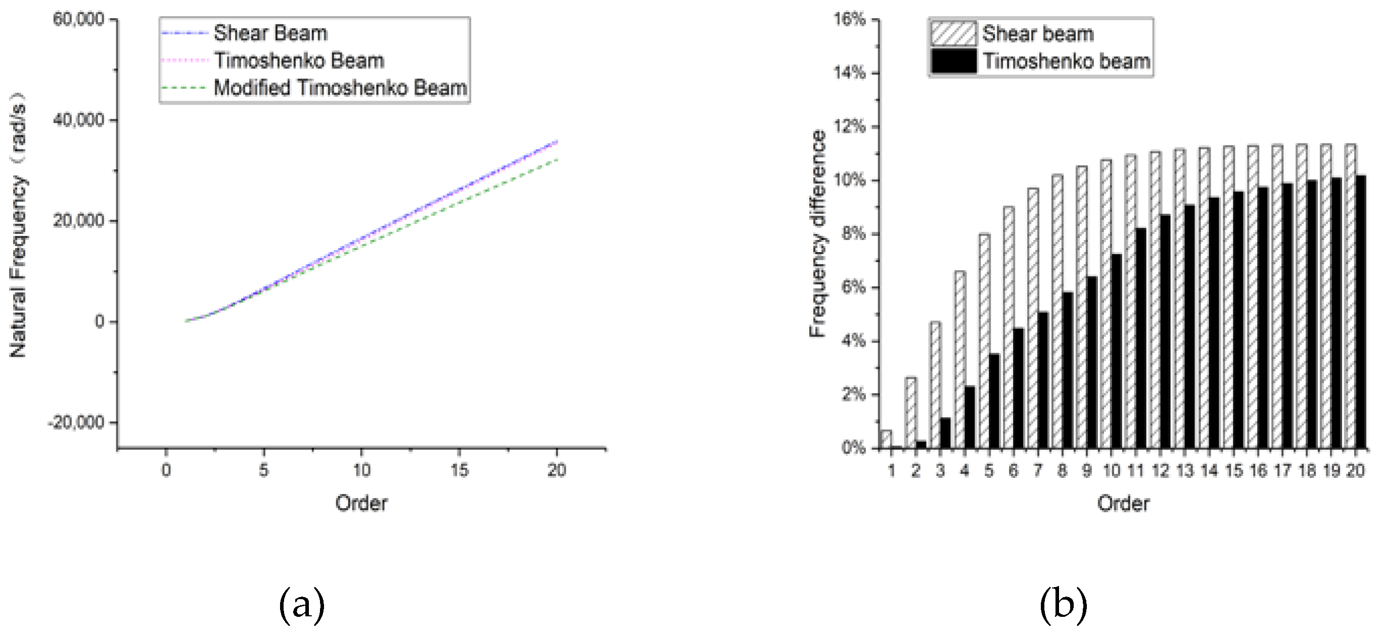
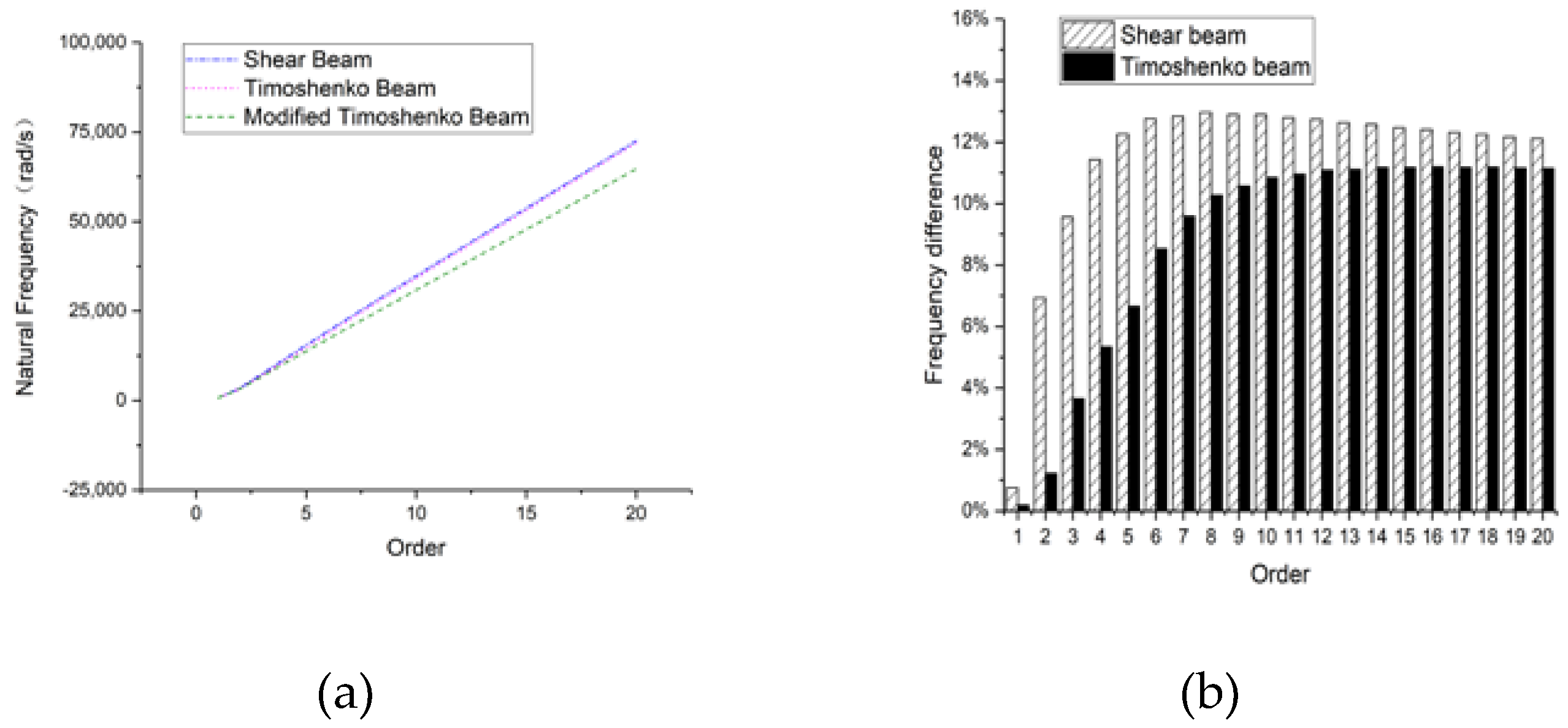
Figure 4, Figure 5 and Figure 6 show the natural frequencies of a hinged-hinged beam with the rectangular section subjected to different beam models. All first subgraphs of these 3 figures show the overall frequency curves, from which the same variation trend of the natural frequencies can be found for all five beam theories, i.e., Bernoulli–Euler beam, Rayleigh beam, shear beam, Timoshenko beam, and modified Timoshenko beam.
The Bernoulli–Euler model provides acceptable frequencies at lower orders while loses its rationality and feasibility with the order increasing. For Rayleigh beam theory, which takes the effect of rotary inertia due to flexural deformation into account, its natural frequencies are substantially reduced compared with the Bernoulli–Euler beam. However, the result is still much higher than those of other beams. Therefore, we could lay more emphasis on the shear beam, Timoshenko beam, and the modified Timoshenko beam without considering Bernoulli–Euler beam and Rayleigh beam.
It can be noted that the results obtained from the shear beam, Timoshenko beam, and the modified Timoshenko beam are generally common; however, the difference between the shear model and Timoshenko beam is much less. As can be seen from Figure 4b, when the beam length is 8 m, the frequency difference between the shear model and the modified Timoshenko beam is 12.3% at the order of 20 and 8.8% between the Timoshenko beam and the modified Timoshenko beam. The major distinction between the shear model and Timoshenko model is whether rotary inertia due to flexural deformation has been concerned, and the modified Timoshenko beam further takes rotary inertia due to shear deformation into account based on the Timoshenko beam. Therefore, the consequence shows that rotary inertia caused by the shear deformation is nonnegligible.
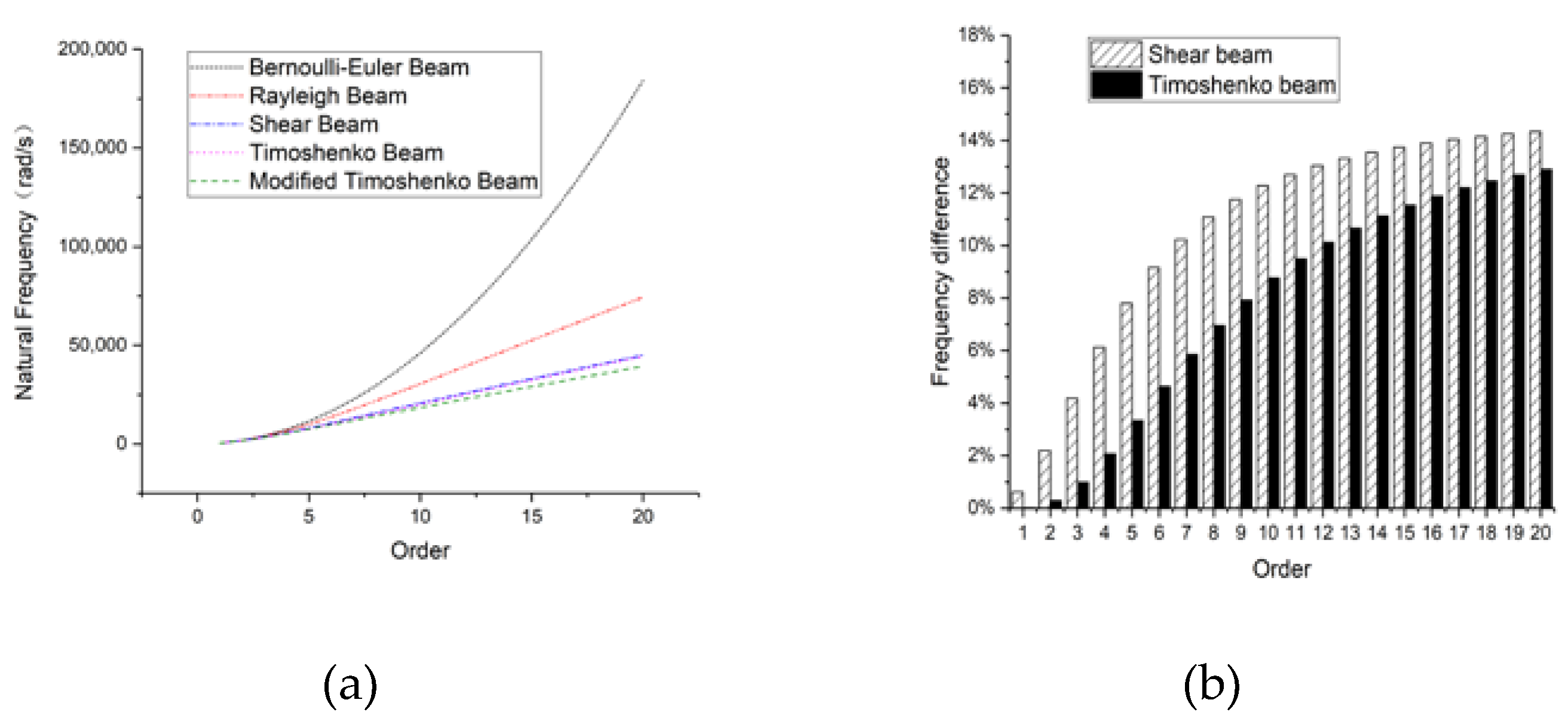
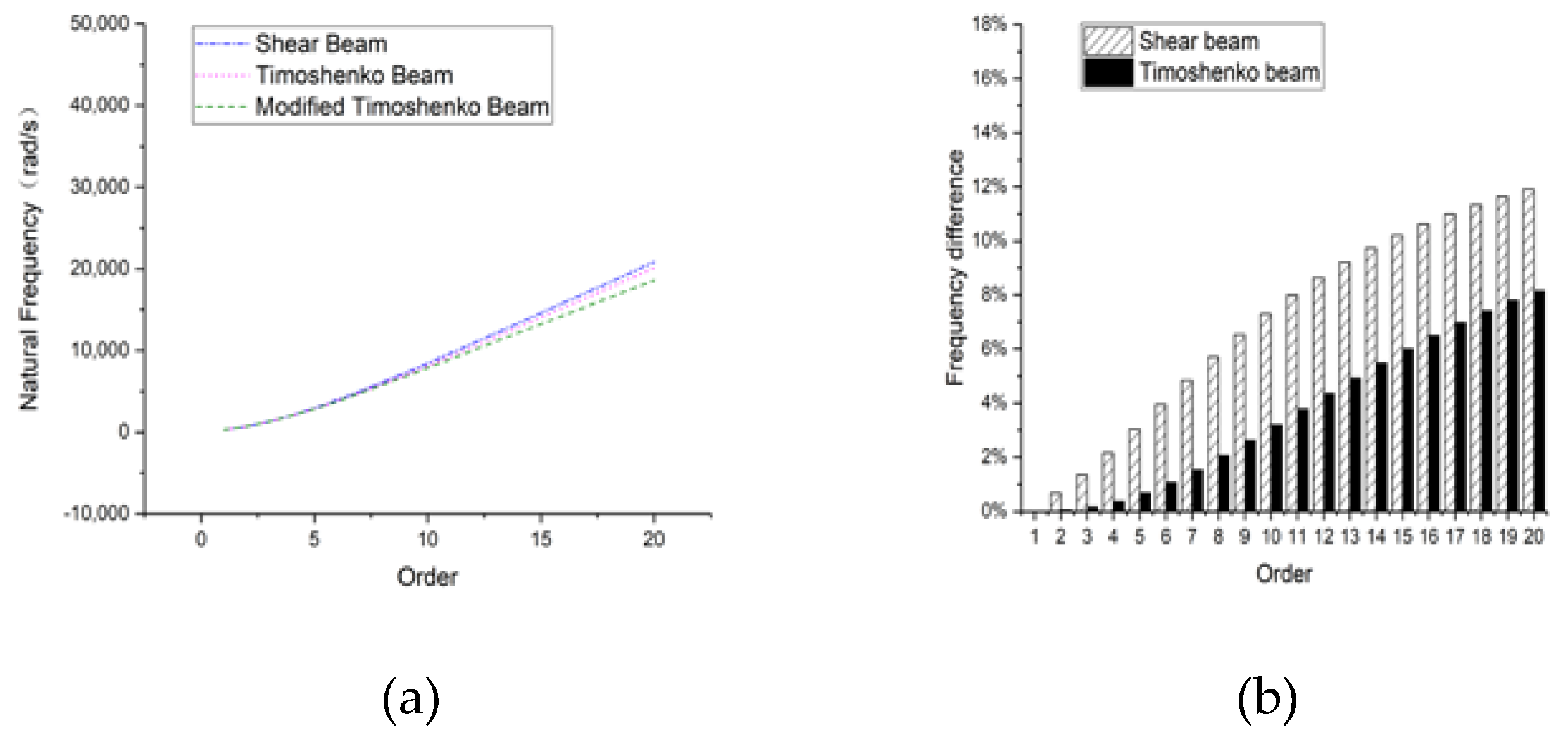
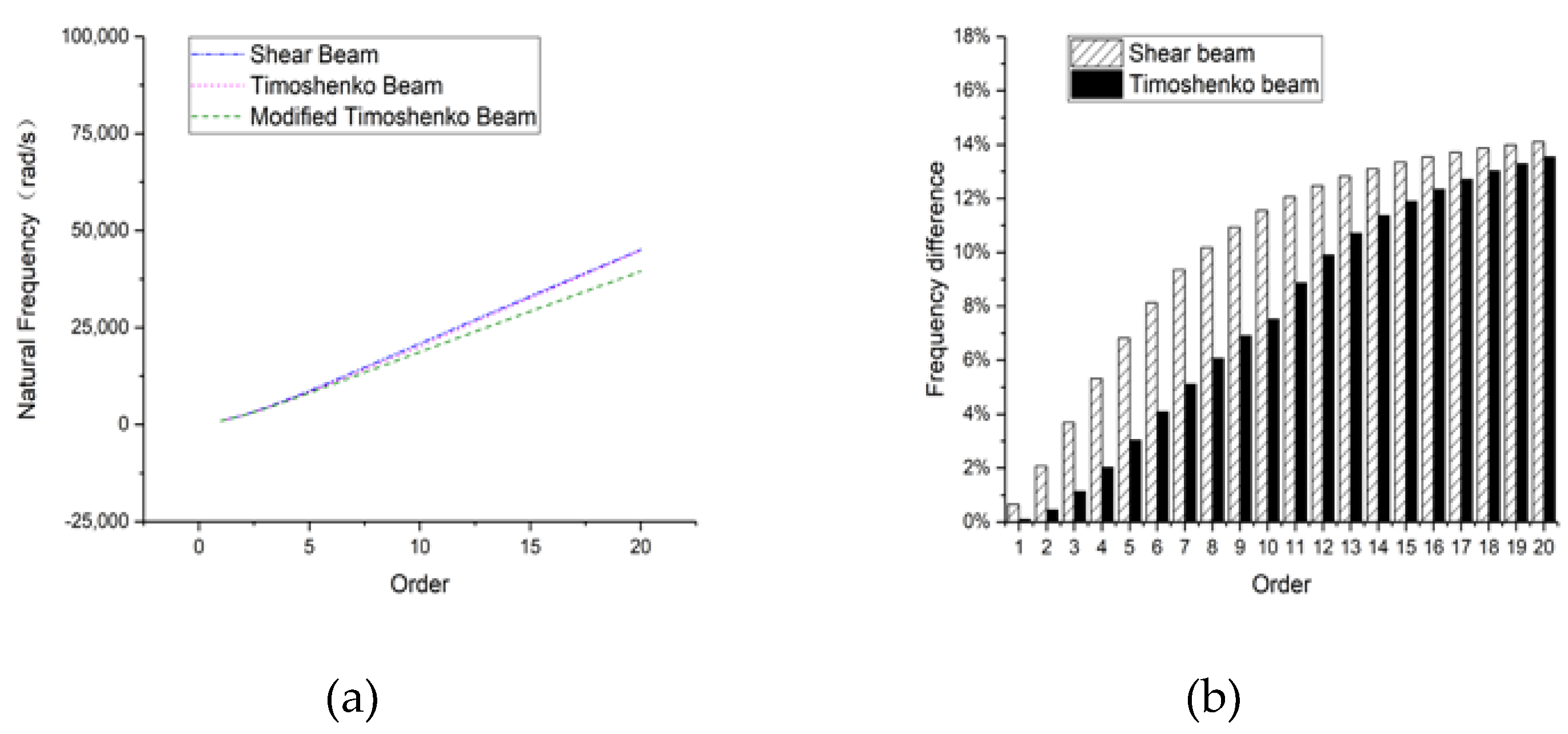
As can be seen from Figure 5 and Figure 6, when the beam length reduces to 4 or 2 m, the difference between the shear beam and the Timoshenko beam has also been reduced. Actually, for a 2-m-long beam, the frequency difference between the shear beam and modified Timoshenko beam is 15.0% at the 20th order, almost the same as that between the Timoshenko beam and modified Timoshenko beam, which is 14.5%. The result illustrates that the effect of the rotary inertia caused by the flexural deformation becomes small when the beam tends to be non-slender. On the contrary, the significance of the rotary inertia due to shear deformation for non-slender beam emerges. In addition, the fact that the frequency difference has grown enormously for both shear beam and Timoshenko beam illustrates that the rotary inertia caused by the shear deformation has an increasing influence on natural frequencies with the beam is shortened. It is intelligible for the reason that the effect of shear deformation as well as the rotary inertia that it causes becomes notable when the beam tends to be non-slender. In the meantime, the effect of bending moment and rotary inertia that it causes decreases. As a consequence, such modification is essential if the high-frequency band is considered.

3.1.2. Clamped-Clamped

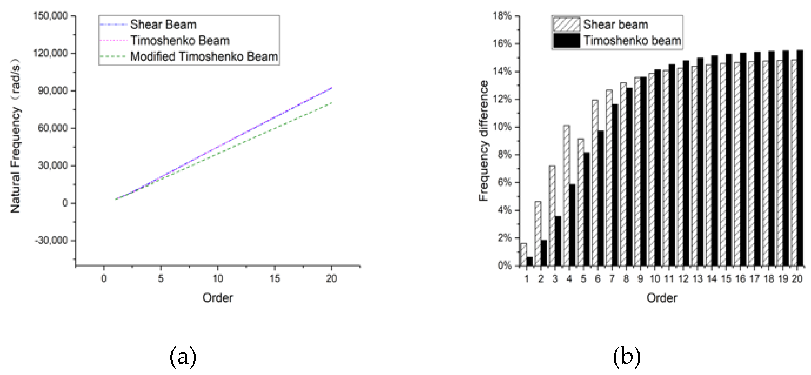
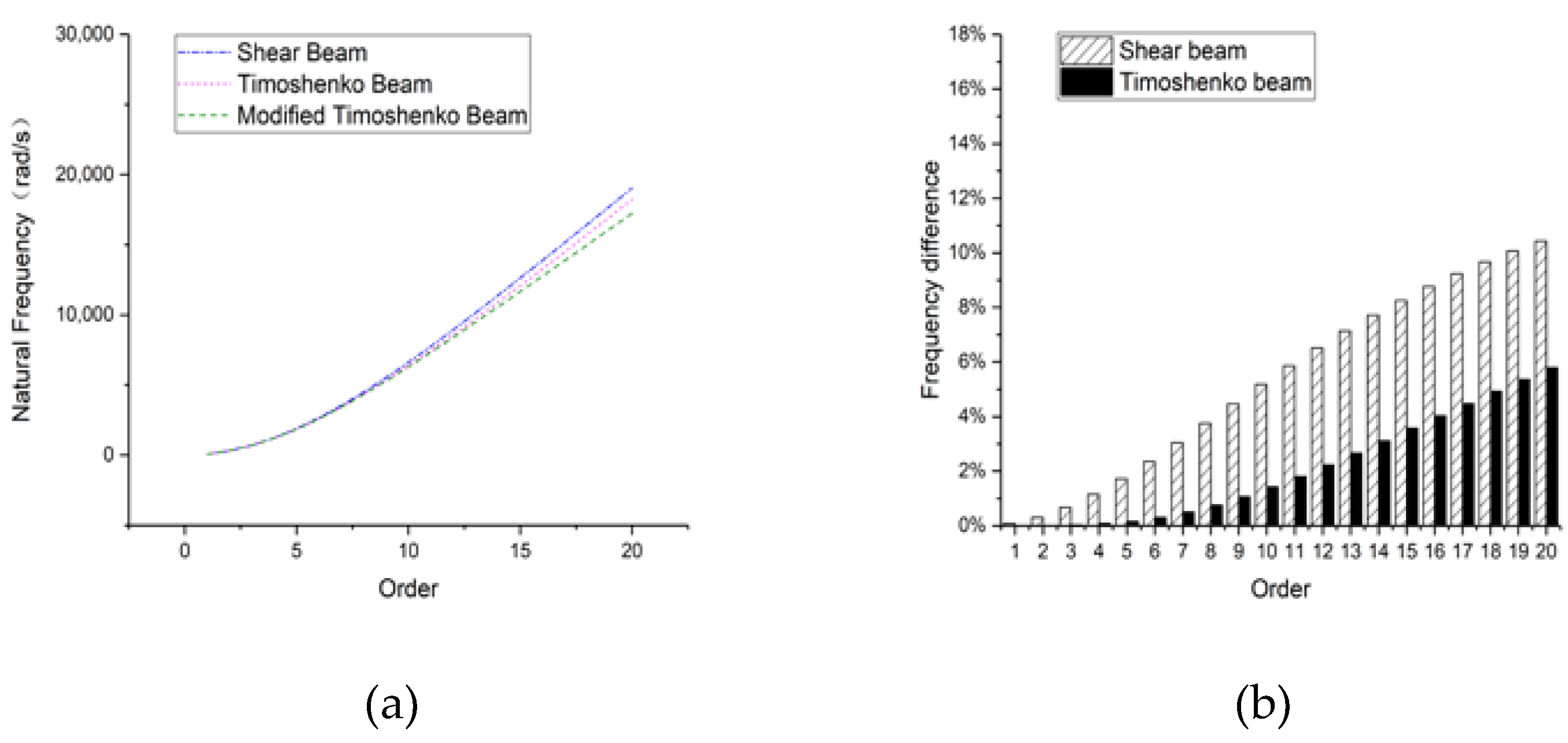
Figure 7, Figure 8 and Figure 9 demonstrate the natural frequencies, as well as the frequency difference, of a clamped-clamped beam in the rectangular section. The natural frequency properties of the clamped-clamped beam are analogous to that of the simply supported beam. With the order increasing, the frequency difference between either the shear beam or the Timoshenko beam and the modified Timoshenko beam increases sharply and more notably when the beam becomes shorter, similar to the foregoing discussion that the rotary inertia caused by the shear deformation plays an increasingly important role as the order increases or the beam length decreases.

3.1.3. Clamped-Free

From Figure 10, Figure 11 and Figure 12, a conclusion can be drawn similarly to that of the hinged-hinged beam. When the beam length is 8 m, the frequency difference of shear model is much bigger than the Timoshenko beam compared with modified Timoshenko beam as order increases; the reason for this is the effect of the rotary inertia caused by flexural deformation. However, the difference for both of these models compared with the modified Timoshenko model becomes obviously large at higher orders when the beam length tends to be shorter; thus, the rotary inertia caused by the shear deformation should not be neglected at higher orders in such a case.

3.2. Rectangular Hollow Section Beam

3.2.1. Hinged-Hinged

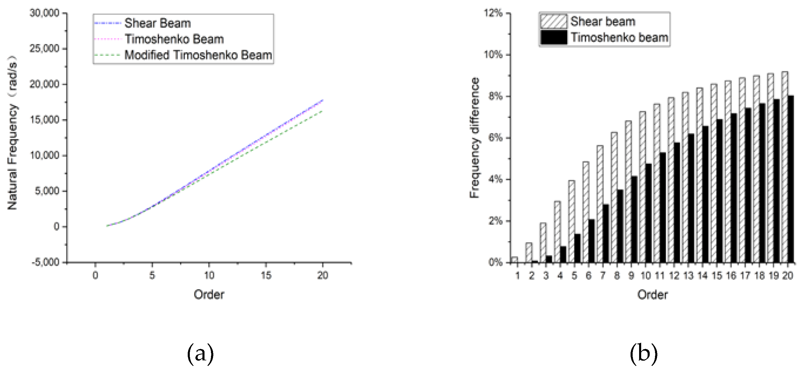
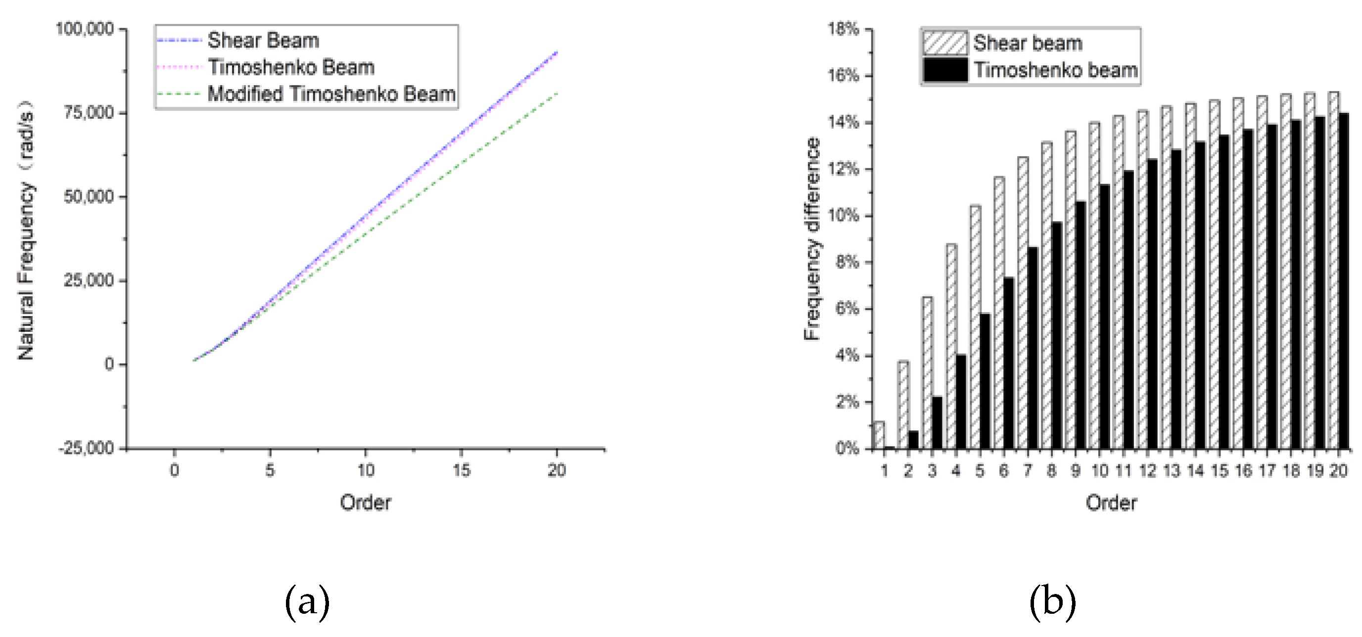
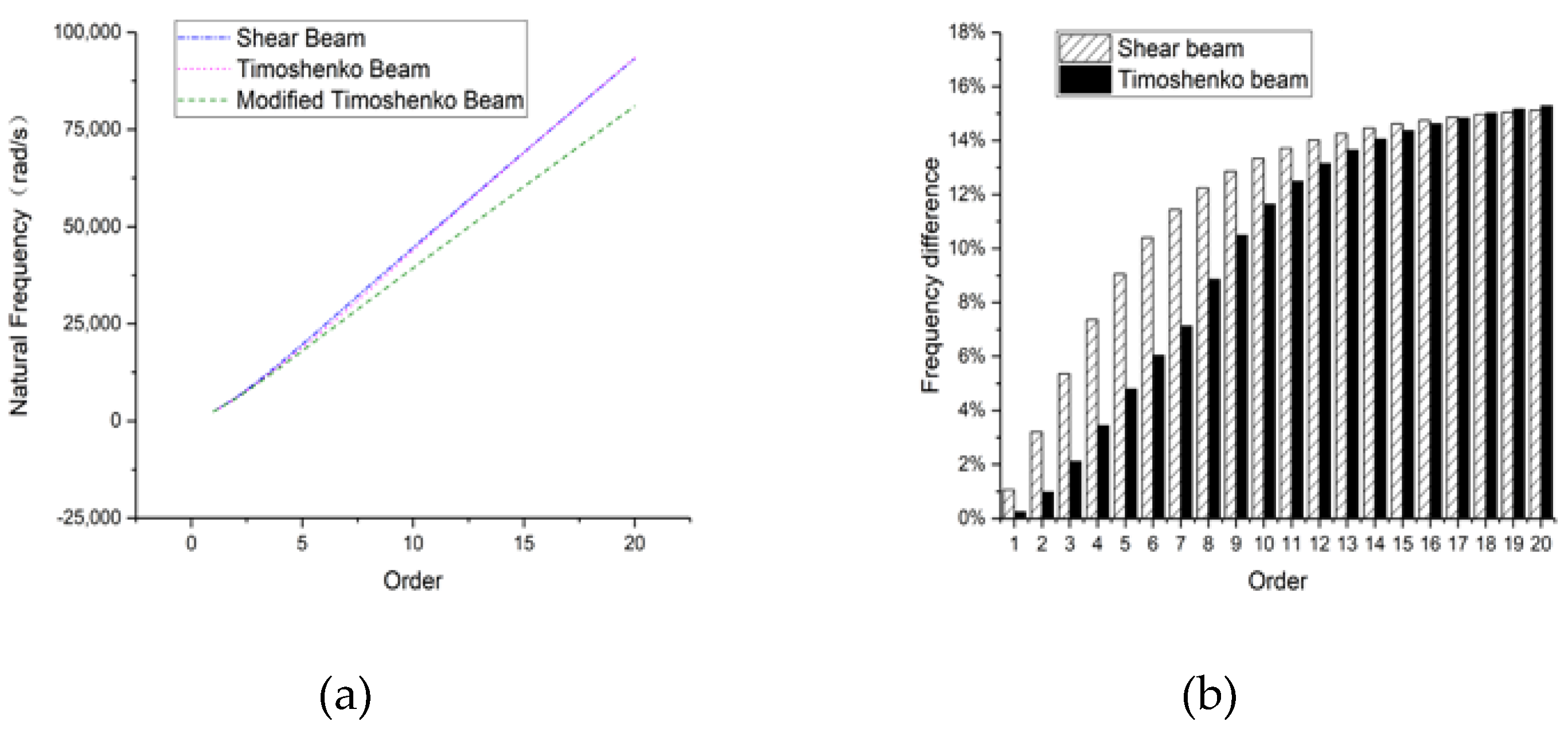
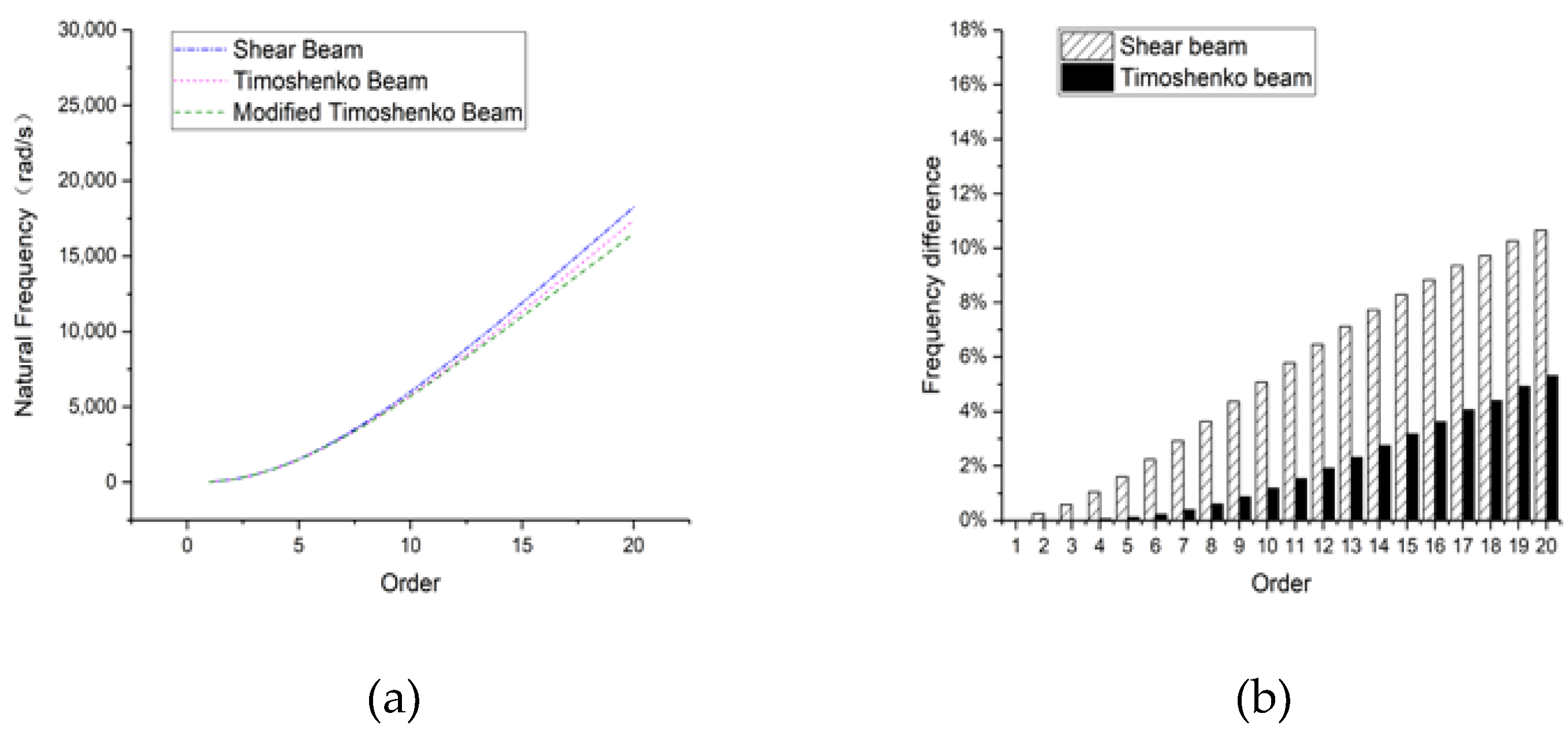
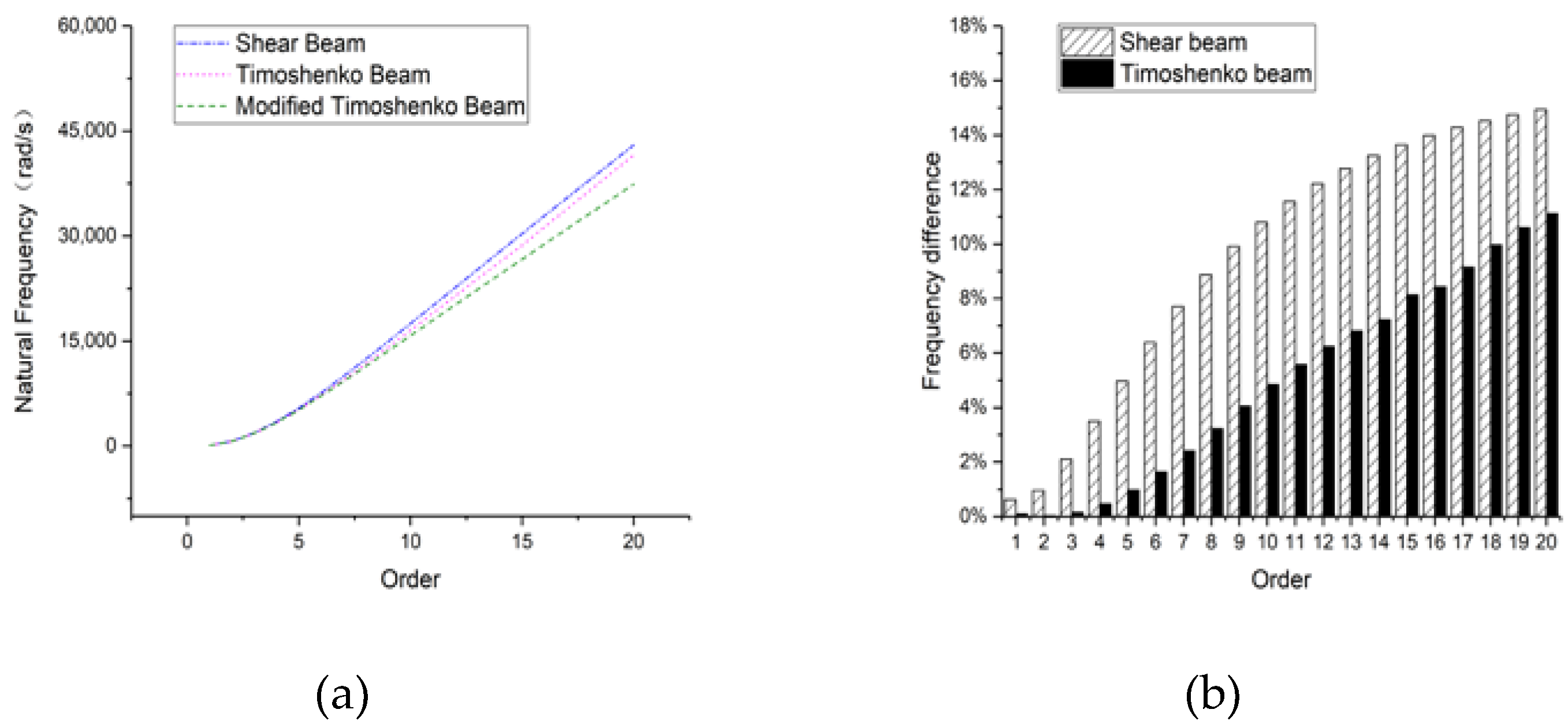
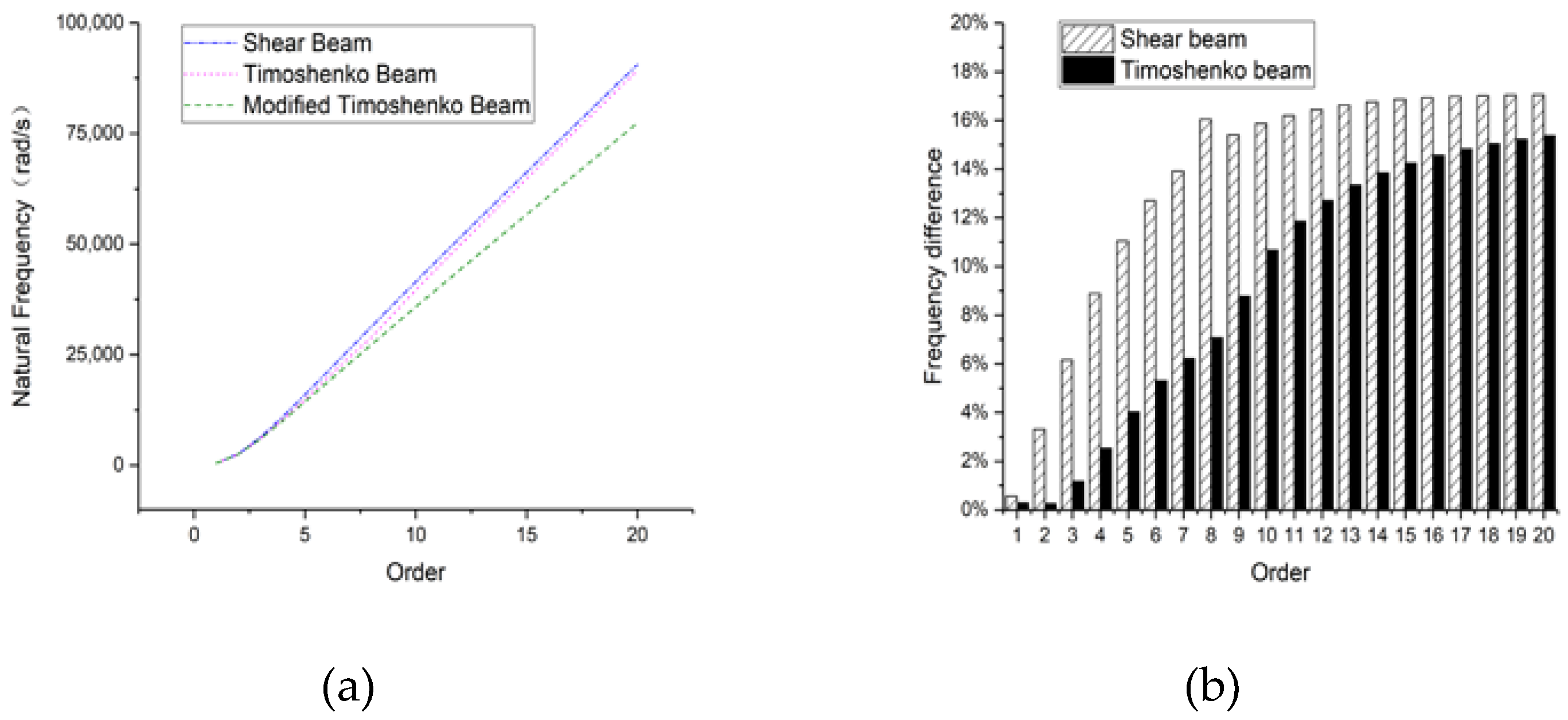
Figure 13, Figure 14 and Figure 15 show the natural frequencies of rectangular hollow section beams in different slender conditions. It can be seen that the simulation results derived from a rectangular hollow section beam bear resemblance to those of a rectangular section beam. When the beam length is 8 m, the frequency difference is 9.18% between shear beam and modified Timoshenko beam and 8.03% between Timoshenko beam and the modified Timoshenko beam. When the beam length reduces to 4 m or 2 m, the effect of the rotary inertia caused by shear deformation is more phenomenal. At the 20th-order frequency when the beam length is 2 m, the frequency difference is 10.01% between the shear beam and the modified Timoshenko beam and 9.92% between the Timoshenko beam and the modified Timoshenko beam. Therefore, we will draw the same conclusion as that for the rectangular section beam, which also verifies the necessity of the modification as well.

3.2.2. Clamped-Clamped

Figure 16, Figure 17 and Figure 18 show that the frequency characteristics of the clamped-clamped beam in a rectangular hollow cross section share common results with the above conclusions. When the beam length is relatively large, the bending moment plays a key role, and it is where the difference mainly derives from. When the length decreases, the rotary inertia caused by shear deformation could not be ignored any more, which explains that, at higher orders, the difference for both the shear model and Timoshenko model compared with the modified Timoshenko model remains quite large. Therefore, the modified Timoshenko beam is also verified to be necessary in non-slender beam and at higher-order frequencies.

3.2.3. Clamped-Free

Similarly, frequency characteristics of the clamped-free beam in a rectangular hollow section are also in accordance with the above cases as are shown in Figure 19, Figure 20 and Figure 21. When the beam becomes shorter, the rotary inertia caused by the shear deformation is no longer negligible for both the shear model and Timoshenko model at higher orders; thus, the modified Timoshenko beam which takes this important effect into account makes sense.

3.3. Circular Section Beam

3.3.1. Hinged-Hinged

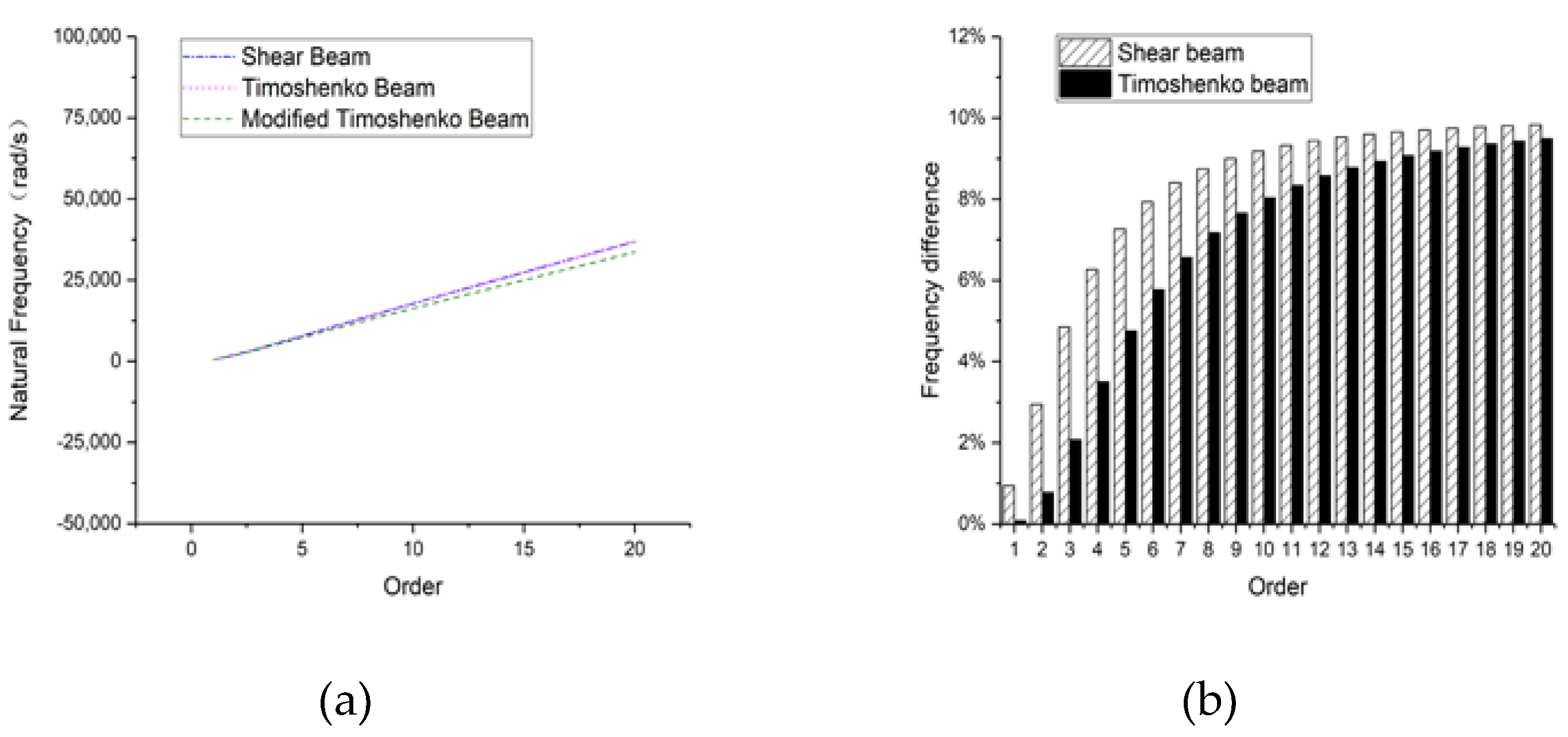
In the following 3 figures (Figure 22, Figure 23 and Figure 24), natural frequencies of a circular section beam will be presented, and similarly, the conclusion is consistent. When the beam length is 8 m, the frequency difference is 10.4% between the shear beam and the modified Timoshenko beam and 5.79% between the Timoshenko beam and the modified Timoshenko beam. Similarly, when the beam reduces to 4 m or 2 m, the effect of the rotary inertia caused by shear deformation is so phenomenal that it shall not be neglected. At 2 m length, the difference is 15.3% between the shear beam and the modified Timoshenko beam and 14.4% between the Timoshenko beam and the modified Timoshenko beam. Hence, regularity also applies to the circular section beam.

3.3.2. Clamped-Clamped

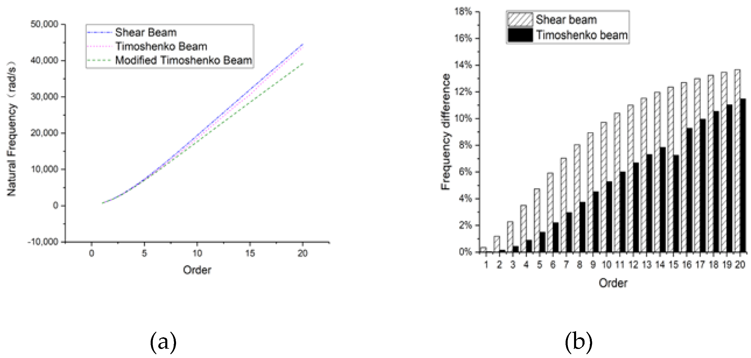
As can be seen from the following three figures (Figure 25, Figure 26 and Figure 27), we can draw a similar conclusion for the frequency characteristics of the clamped-clamped beam with a circular section. When the beam is 8 m long, the difference for the shear model and Timoshenko model compared with the modified Timoshenko beam increases almost linearly as the order increases. However, for a less slender beam, the difference increases almost quadratically, which means the rotary inertia caused by shear deformation plays an increasingly important role as order increases for a non-slender beam. On the whole, the necessity of the modification has been proven to be reasonable.

3.3.3. Clamped-Free

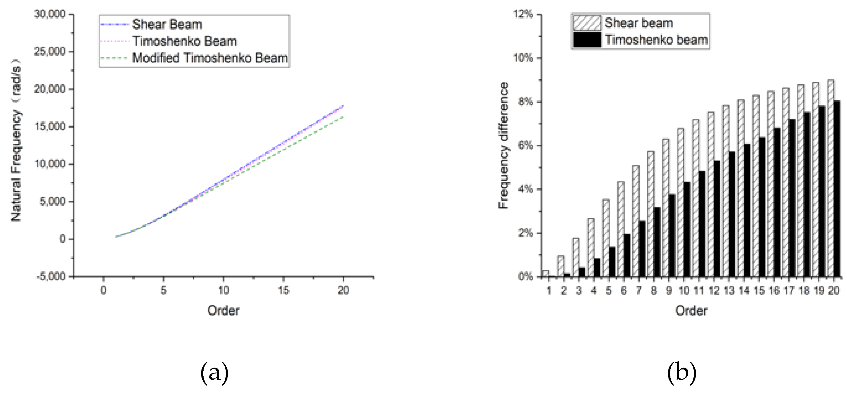
Figure 28, Figure 29 and Figure 30 show the frequency characteristics of the clamped-free in a circular section, which is identical to the foregoing discussion. Figure 28 demonstrates the frequency difference for the beam length at 8 m, where the difference for both the shear model and Timoshenko model increases almost linearly as order increases. The reason is that the bending moment plays a key role when the beam is relatively long or slender. When the beam length decreases to less slender, as can be seen from Figure 29 and Figure 30, the shear deformation and rotary inertia caused by shear deformation becomes obvious at higher orders, which explains the phenomenon that the frequency difference stays large at higher orders. In all, the modification for a Timoshenko beam is quite important when it comes to non-slender beams at its higher orders.

4. Conclusions

Since the Timoshenko beam was introduced to engineering fields, many efforts have been devoted and many problems are yet to handle. A modified Timoshenko beam has been proposed to solve the overestimation of the natural frequency for the Timoshenko beam and the problem on how many frequency spectra exist in the beam. The modified Timoshenko beam takes into account the rotary inertia caused by the shear deformation, and the equation of motion and other dynamic characteristics have been derived. It has been theoretically proven to solve the overestimation. This article mainly revolves around the effects of the cross-sectional forms on the natural frequencies. Through the simulation, the validity of the modified Timoshenko beam has been confirmed. It is found that, for all three cross-sectional forms, rotary inertia due to shear deformation plays an important role in natural frequencies, no matter for slender beam or non-slender beam. Furthermore, the effects are more conspicuous for non-slender beam where the shear deformation and rotary inertia that it causes theoretically have more influences on natural frequencies. Comparisons of three cross-sectional forms further prove the necessity and validity of the modification. The result may help reduce the error of the Timoshenko beam and may further establish the authority of the modified Timoshenko beam.

Author Contributions

Conceptualization, C.W. and S.X.; Theoretical derivation, C.W. and L.X.; Numerical simulation, H.J., C.Y. and Y.D.; Data Analysis, L.X. and H.T.; Supervision, C.W., C.Y. and S.X.; Writing—original draft, H.J. and C.W.; Writing—review & editing, C.Y. and S.X. All authors have read and agreed to the published version of the manuscript.

Funding

This research was funded by National Key Research and Development Program of China (No. 2017YFC0806001); the Innovative Venture Technology Investment Project of Hunan Province (2018GK5028); the Fund for Distinguished Young Scientists of Jiangsu Province (BK20190013) and the National Natural Science Foundation of China (Nos. 51778490 and 51578140).

Conflicts of Interest

The authors declare no conflict of interest.

References

  1. Timoshenko, S.P. History of Strength of Materials; Dover Publications: New York, NY, USA, 1953. [Google Scholar]
  2. Strutt, J.W. Theory of Sound; Macmillan Publications Co.: London, UK, 1877. [Google Scholar]
  3. Abbas, B.A.H.; Thomas, J. The second frequency spectrum of Timoshenko beams. J. Sound Vib. 1977, 51, 123–137. [Google Scholar] [CrossRef]
  4. Timoshenko, S.P. On the correction for shear of the differential equation for transverse vibrations of bars of uniform cross-section. Philos. Mag. 1921, 41, 744–746. [Google Scholar] [CrossRef] [Green Version]
  5. Timoshenko, S.P. On the transverse vibrations of bars of uniform cross-section. Philos. Mag. 1922, 43, 125–131. [Google Scholar] [CrossRef] [Green Version]
  6. Traill-Nash, R.W.; Collar, A.R. The effects of shear flexibility and rotatory inertia on the bending vibrations of beams. Q. J. Mech. Appl. Math. 1953, 2, 186–222. [Google Scholar] [CrossRef]
  7. Dolph, C.L. On the Timoshenko theory of transverse beam vibrations. Q. Appl. Math. 1954, 12, 175–187. [Google Scholar] [CrossRef] [Green Version]
  8. Herrmann, G. Forced motions of Timoshenko beams. J. Appl. Mech. Trans. ASME 1955, 77, 53–56. [Google Scholar]
  9. Boley, B.A.; Chao, C.C. Some Solutions of the Timoshenko Beam Equations; Department of Civil Engineering and Engineering Mechanics, Institute of Air Flight Structures, Columbia University: New York, NY, USA, 1954. [Google Scholar]
  10. Huang, T.C. The effect of rotatory inertia and of shear deformation on the frequency and normal mode equations of uniform beams with simple end conditions. J. Appl. Mech. 1961, 28, 579–584. [Google Scholar] [CrossRef]
  11. Reismann, H.; Pawlik, P.S. Elastokinetics; West Publishing Co.: New York, NY, USA, 1974. [Google Scholar]
  12. Anderson, R.A. Flexural vibrations in uniform beams according to the Timoshenko theory. J. Appl. Mech. Trans. ASME 1953, 20, 504–510. [Google Scholar]
  13. Downs, B. Transverse vibration of a uniform, simply supported Timoshenko beam without transverse deflection. J. Appl. Mech. Trans. ASME 1977, 99, 103. [Google Scholar] [CrossRef]
  14. Levinson, M.; Cooke, D.W. On the two frequency spectra of Timoshenko beams. J. Sound Vib. 1982, 84, 319–326. [Google Scholar] [CrossRef]
  15. Abbas, B.A.H.; Thomas, J. Finite element model for dynamic analysis of Timoshenko beam. J. Sound Vib. 1975, 41, 291–299. [Google Scholar]
  16. Stephen, N.G. On the variation of Timoshenko’s shear coefficient with frequency. J. Appl. Mech. 1978, 45, 695–696. [Google Scholar] [CrossRef]
  17. Stephen, N.G. Timoshenko’s shear coefficient from a beam subjected to gravity loading. J. Appl. Mech. 1980, 47, 121–127. [Google Scholar] [CrossRef]
  18. Stephen, N.G. The second spectrum of Timoshenko beam theory—Further assessment. J. Sound Vib. 1980, 292, 372–389. [Google Scholar] [CrossRef] [Green Version]
  19. Murin, J.; Aminbaghai, M.; Kutis, V. Exact solution of the bending vibration problem of FGM beams with variation of material properties. Eng. Struct. 2010, 32, 1631–1640. [Google Scholar] [CrossRef]
  20. Wan, C. The Modification of Motion Equation of Timoshenko Beam and Its Application in Impact Responses of Structures. Master thesis, Tongji University, Shanghai, China, 2003. (In Chineses). [Google Scholar]
  21. Wan, C.; Chen, R.; Xue, S.; Wu, Z. Development of a novel beam model and its dynamic characteristics. Mech. Adv. Mater. Struct. 2014, 2, 402–412. [Google Scholar] [CrossRef]
  22. Chen, R.; Wan, C.; Xue, S.; Tang, H. Modification of motion equation of Timoshenko beam and Its effect. J. Tongji Univ. Nat. Sci. 2005, 33, 711–715. [Google Scholar]
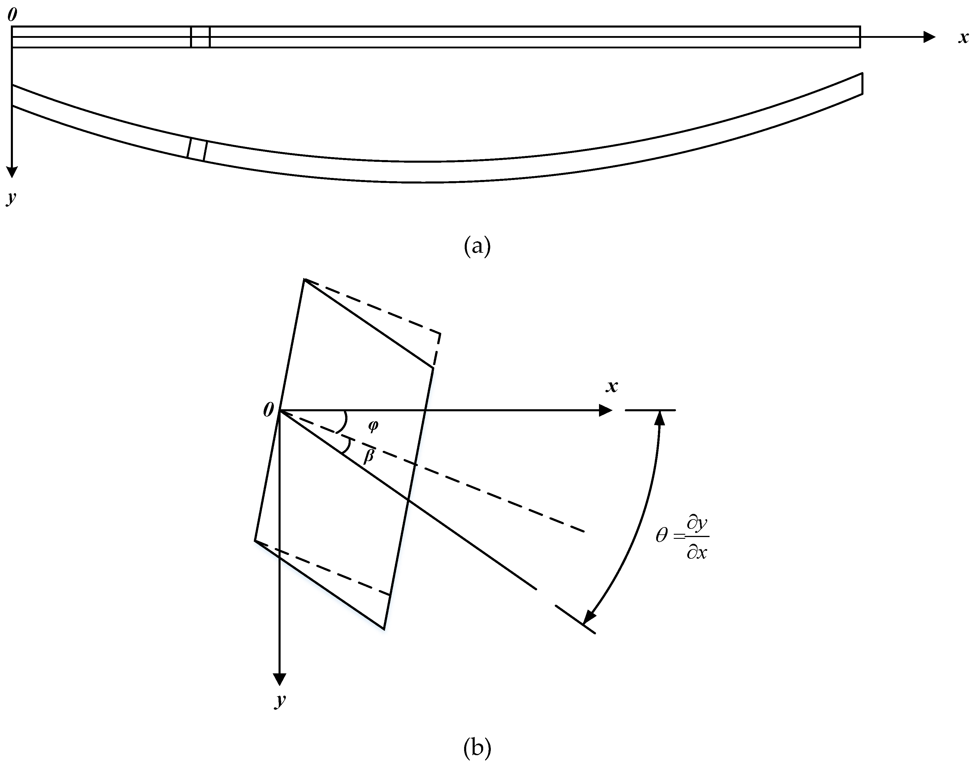
Figure 1. Deformation of the modified Timoshenko beam and a differential element diagram: (a) the lateral deformation under lateral load and (b) the element deformation.
Applsci 10 05245 g001
Figure 2. Free body diagram for a differential element.
Applsci 10 05245 g002
Figure 3. Cross-sectional forms: (a) rectangular section, (b) rectangular hollow section, and (c) circular section.
Applsci 10 05245 g003
Figure 4. Natural frequencies of the 8-m-long beam: (a) overall frequency curve and (b) frequency difference compared with a modified Timoshenko beam.
Applsci 10 05245 g004
Figure 5. Natural frequencies of the 4-m-long beam: (a) overall frequency curve and (b) frequency difference compared with a modified Timoshenko beam.
Applsci 10 05245 g005
Figure 6. Natural frequencies of the 2-m-long beam: (a) overall frequency curve and (b) frequency difference compared with a modified Timoshenko beam.
Applsci 10 05245 g006
Figure 7. Natural frequencies of the 8-m-long beam: (a) overall frequency curve and (b) frequency difference compared with a modified Timoshenko beam.
Applsci 10 05245 g007
Figure 8. Natural frequencies of the 4-m-long beam: (a) overall frequency curve and (b) frequency difference compared with a modified Timoshenko beam.
Applsci 10 05245 g008
Figure 9. Natural frequencies of the 2-m-long beam: (a) overall frequency curve and (b) frequency difference compared with a modified Timoshenko beam.
Applsci 10 05245 g009
Figure 10. Natural frequencies of the 8-m-long beam: (a) overall frequency curve and (b) frequency difference compared with a modified Timoshenko beam.
Applsci 10 05245 g010
Figure 11. Natural frequencies of the 4-m-long beam: (a) overall frequency curve and (b) frequency difference compared with a modified Timoshenko beam.
Applsci 10 05245 g011
Figure 12. Natural frequencies of the 2-m-long beam: (a) overall frequency curve and (b) frequency difference compared with a modified Timoshenko beam.
Applsci 10 05245 g012
Figure 13. Natural frequencies of the 8-m-long beam: (a) overall frequency curve and (b) frequency difference compared with a modified Timoshenko beam.
Applsci 10 05245 g013
Figure 14. Natural frequencies of the 4-m-long beam: (a) overall frequency curve and (b) frequency difference compared with a modified Timoshenko beam.
Applsci 10 05245 g014
Figure 15. Natural frequencies of the 2-m-long beam: (a) overall frequency curve and (b) frequency difference compared with a modified Timoshenko beam.
Applsci 10 05245 g015
Figure 16. Natural frequencies of the 8-m-long beam: (a) overall frequency curve and (b) frequency difference compared with a modified Timoshenko beam.
Applsci 10 05245 g016
Figure 17. Frequencies of the 4-m-long beam: (a) overall frequency curve and (b) frequency difference compared with a modified Timoshenko beam.
Applsci 10 05245 g017
Figure 18. Natural frequencies of the 2-m-long beam: (a) overall frequency curve and (b) frequency difference compared with a modified Timoshenko beam.
Applsci 10 05245 g018
Figure 19. Natural frequencies of the 8-m-long beam: (a) overall frequency curve and (b) frequency difference compared with a modified Timoshenko beam.
Applsci 10 05245 g019
Figure 20. Natural frequencies of the 4-m-long beam: (a) overall frequency curve and (b) frequency difference compared with a modified Timoshenko beam.
Applsci 10 05245 g020
Figure 21. Natural frequencies of the 2-m-long beam: (a) overall frequency curve and (b) frequency difference compared with a modified Timoshenko beam.
Applsci 10 05245 g021
Figure 22. Natural frequencies of the 8-m-long beam: (a) overall frequency curve and (b) frequency difference compared with a modified Timoshenko beam.
Applsci 10 05245 g022
Figure 23. Natural frequencies of the 4-m-long beam: (a) overall frequency curve and (b) frequency difference compared with a modified Timoshenko beam.
Applsci 10 05245 g023
Figure 24. Natural frequencies of the 2-m-long beam: (a) overall frequency curve and (b) frequency difference compared with a modified Timoshenko beam.
Applsci 10 05245 g024
Figure 25. Natural frequencies of the 8-m-long beam: (a) overall frequency curve and (b) frequency difference compared with a modified Timoshenko beam.
Applsci 10 05245 g025
Figure 26. Natural frequencies of the 4-m-long beam: (a) overall frequency curve and (b) frequency difference compared with a modified Timoshenko beam.
Applsci 10 05245 g026
Figure 27. Natural frequencies of the 2-m-long beam: (a) overall frequency curve and (b) frequency difference compared with a modified Timoshenko beam.
Applsci 10 05245 g027
Figure 28. Natural frequencies of the 8-m-long beam: (a) overall frequency curve and (b) frequency difference compared with a modified Timoshenko beam.
Applsci 10 05245 g028
Figure 29. Natural frequencies of the 4-m-long beam: (a) overall frequency curve and (b) frequency difference compared with a modified Timoshenko beam.
Applsci 10 05245 g029
Figure 30. Natural frequencies of the 2-m-long beam: (a) overall frequency curve and (b) frequency difference compared with a modified Timoshenko beam.
Applsci 10 05245 g030