Article

Electrospark Method in Galvanic Wastewater Treatment for Heavy Metal Removal

by
Oleksandr Petrov
1,*,
Sergei Petrichenko
2,
Anna Yushchishina
2,
Olena Mitryasova
3 and
Volodymyr Pohrebennyk
4
1
Department of Applied Computer Science, AGH University of Science and Technology, Kraków 30-059, Poland
2
Institute of Impulse Processes and Technologies of NAS of Ukraine, Mykolaiv 54018, Ukraine
3
Ecology Department, Petro Mohyla Black Sea National University, Mykolaiv 54003, Ukraine
4
Department of Ecological Safety and Nature Protection Activity, Lviv Polytechnic National University, Lviv 79057, Ukraine
*
Author to whom correspondence should be addressed.
Appl. Sci. 2020, 10(15), 5148; https://doi.org/10.3390/app10155148
Submission received: 24 June 2020 / Revised: 9 July 2020 / Accepted: 20 July 2020 / Published: 27 July 2020

Abstract

:
The objective of this research is to improve water treatment use of the electric spark method. Studies on the treatment of multicomponent galvanic effluent by the electric spark method using metal loading (Fe, Al) and low-voltage (up to 1000 V) equipment have been carried out. The factors that have the largest influence on the degree of galvanic wastewaters purification are the conditions and parameters of the discharge pulse—an efficiency of approximately 0.8–0.85 has a specific energy, which at moderate concentrations of pollutants can be less than 65 kJ/dm3 (18 kWh/m3)—and the metal loading height. Other variable technological parameters can serve either as scaling tools or as methods for regulating the operation of electrical equipment. The research shows that the degree of purification depends on the specific energy and the height of the metal loading of the reactor, and it weakly depends on the pulse energy and the speed of its input. The concentrations of heavy metals (Zn2+, Cr6++Cr3+, Cu2+) in the treated water are significantly lower than their maximal permissible concentrations. The electric spark method allows us to achieve highly efficient results of wastewater treatment from heavy metals.

1. Introduction

Wastewaters that contain heavy metals present an environmental risk. Anthropogenic sources of biosphere pollution by heavy metals include ferrous and nonferrous metallurgy enterprises (aerosol emissions, industrial discharges), mechanical engineering (galvanic baths, copper plating, nickel plating, chrome plating, cadmium plating), battery recycling plants, road transport, and so on [1,2,3,4,5,6]. Heavy metals enter into reservoirs with discharges from mining and metallurgical enterprises, as well as chemical and light industry enterprises, where their compounds are used in various technological processes. So, many chromium and nickel salts are used to galvanically coat the surfaces of metal products. Compounds of copper, zinc, cobalt, and titanium are used in the production of dyes, etc. Issues of water quality and status are among the priorities in the environmental policy of European countries [7,8,9,10,11]. Therefore, the question of finding effective wastewater treatment methods containing heavy metals is an urgent issue. There are different physical, chemical, biological, electrochemical, and galvanocoagulation methods that are used for the treatment of wastewater [12,13]. The most common method of wastewater treatment is a reagent. Its advantages are the relatively high productivity and low energy consumption, and its disadvantages are low efficiency (up to 10% of heavy metal salts remain in solution). The traditionally used biological treatment processes need a large operational area and much time. Chemical coagulation processes are very slow, with a large amount of sludge. The disadvantage of ion exchange techniques is the high cost of purification. Electrocoagulation and electroflotation are promising electrochemical methods. The advantages of the electrocoagulation method are its environmental friendliness, versatility, low operating costs, low energy requirements, minimal chemical additives, and sludge minimization. In particular, it is used for wastewater treatment in the printing, textile, meat processing, oil refining, dairy, and leather industries, in agriculture, and in the service sector: car washes, restaurants, cafes, laundries, etc. Among many methods, coagulation methods for wastewater treatment from heavy metal ions are the most effective and used [14,15]. Reagent coagulation is based on the hydrolysis of polyvalent metal salts (aluminum and iron), which lead to the formation of highly dispersed oxides and hydroxides of these elements, which can actively adsorb impurities of heavy metal ions from wastewater. Significant disadvantages by the reagent purification method are the additional pollution of effluents due to the introduction of cations and anions of reagents, obtaining dehydrated and not recyclable sludge. Coagulants based on iron and aluminum are capable of forming multiply charged multinuclear complexes; therefore, such coagulants have good adsorption characteristics [15,16].
In electrocoagulation methods of galvanic wastewater treatment, adsorption-active hydroxides of iron or aluminum are formed by electro erosion by the electrolytic dissolution of steel or aluminum anodes, respectively. In this case, phenomena such as water electrolysis, particles’ polarization, electrophoresis, redox processes, and the interaction of electrolysis products with each other can occur in the electrolyzer [17,18,19,20]. Galvanic coagulation consists of passing wastewater through a galvanic coagulator that contains an active anode and cathode mixture, for example, iron and aluminum chips, iron chips, coke [13], etc. Various investigators have been successfully applied the electrocoagulation process (EC) to remove soluble ions of heavy metals from solutions [21,22]. During the electrocoagulation process, the coagulant continuously enters the contaminated water. This method makes it possible to remove contaminants from wastewater, in particular the metals mercury, cobalt, copper [23,24,25], chromium [26,27,28,29], zinc, cadmium, nickel [30,31,32,33], arsenic, strontium, cesium [34,35], nitrate, phosphate, sulfide, sulfate, sulfite [36,37,38], fluoride, boron [39,40], chemical oxygen demand, clay minerals, and organic substances [41,42,43,44].
Electro-blasting water treatment is used to intensify coagulation processes, i.e., to accelerate a sediment formation. The essence of this method is to pass through the wastewater short-term electrical pulses with electrodes immersed in the solution. Pulsed electric discharge in a liquid is accompanied by a sharp increase in pressure (up to 100–200 MPa), exposure to strong electromagnetic and acoustic fields, cavitation, which creates a powerful flow of liquid, a sharp rise in temperature, and other effects. The discharge interval is practically a low-temperature plasma, which transmits energy to the treated medium. An electric discharge—in fact, an explosion in the aqueous phase—causes complex physicochemical processes in it, which lead to the acceleration of the coagulation of colloidal and suspended substances, as well as the precipitation of suspensions and chemical compounds. A schematic diagram of the discharge–pulse treatment of the liquid is shown in Figure 1. In practice, the electrode system can be placed directly in the pipelines through which industrial effluents are pumped. The electric discharge occurs sequentially from one electrode pair to another. The processing model is selected so that after the operation of the last pair of electrodes, work was ready for the first pair. Water treatment is continuous. The mode of processing depends on the pipe section, a flow speed and necessary sanitary indicators of treatment. All purified water has passed through the zone of high-impulse activation.
The plant for the electric blasting of wastewater is not characterized by high energy consumption, does not require excess costs to ensure the safety of service, and has a relatively small size. The method can accelerate the deposition by almost 7–8 times and significantly reduce the processing time. The positive effect of the method on the deposition rate of solid suspensions is explained by the increased coagulation of mineral particles due to the squeeze of the electric double layer under the action of the high-voltage electric discharge as a result of two opposing forces: electrostatic repulsion and van der Waals gravity.
Electrospark discharge in metal-containing reactors is an effective method for producing coagulative active metal oxides and hydroxides [45,46,47,48]. The method is proposed as an alternative to existing methods for the cleaning of galvanic wastewater. It was shown that it is possible in principle to purify multicomponent galvanic wastewater from heavy metal ions, namely Cr6+, Ni2+, Cu2+, and Zn2+ [44]. In this case, attention is directed to expanding the capabilities of the method, which is aimed primarily at the component treatment of galvanic wastewater, by increasing the operating voltage from 300–600 V to 3–15 kV and by using monometallic metal loading (granules of one metal) [14]. This allowed the treatment of concentrated galvanic wastewater containing Cr6+ to 1000 mg/dm3. However, the further implementation of this method turned out to be economically inexpedient due to the high cost and limited resource of high-voltage equipment, its increased danger, and its low process productivity.
The objective of the work is to study the influence of such technological parameters (specific energy, characteristics of the electric pulses and its frequency, schemes of a channel of purified water) on the efficiency of the treatment process of multicomponent galvanic wastewater in reactors with metallic combined loading using low-voltage (up to 1000 V) electrical equipment.

2. Materials and Methods

The essence of the electrospark method is to pass through wastewater short-term electrical pulses with electrodes immersed in the solution (Figure 2). Pulsed electric discharge in a liquid is accompanied by a sharp increase of pressure (up to 100–200 MPa), exposure to strong electromagnetic and acoustic fields, cavitation, which creates a powerful flow of liquid that converges and diverges, a sharp rise in temperature, and so on. In this case, the discharge gap is practically a low-temperature plasma, which transmits energy to the treated medium.
Electric discharge—in fact, an explosion in the aqueous phase—causes complex physicochemical processes that lead to the decomposition of organic impurities present in wastewater, improving the coagulation of colloidal and suspended solids, as well as the precipitation of suspensions and chemical compounds.
The raw material for the treatment is real wastewater after various galvanic production operations, which is supplied to the treatment facilities of a machine-building enterprise. Galvanic wastewater is multicomponent composition containing ions Cr6+, Ni2+, Cu2+, and Zn2+.
A mixture of metals such as aluminum and iron granules with diameters from 4 to 6 mm is selected as the material for metal loading (Figure 3). This choice is due to the following reasons:
  • the positive result of complex water purification from heavy metal ions during high-voltage electric discharges in reactors, granular metal loading, and the use of these materials [46];
  • the traditional use of iron or aluminum electrolytic soluble anodes during the implementation of the electrocoagulation method for the treatment of galvanic wastewater [15];
  • experience in stabilizing spatially distributed discharges in a layer of aluminum and iron granules using low-voltage (up to 1000 V) electrical equipment [49,50].
The layer of metal-loading granules in the form of a rectangular parallelepiped is characterized by the following sizes: length (l)—the distance between the electrodes; width (b), which is equal to the width of the electrodes, and height (h), which varied depending on the scheme of implementation of the fluid flow. The distance between the electrodes is chosen in such a way as to ensure a stable breakdown along the shortest chain of contacts between the granules from one electrode to another at a given capacitance of the capacitor bank in order to optimize the phase composition of electro erosion particles [49,50,51].
The discharge current and voltage at the inter-electrode gap are recorded with an OWON XDS 3202E oscilloscope, using a divider and shunt of our own manufacture. There are many variants of circuit solutions of sources of electric discharge pulses based on semiconductor switches. To solve the problems of this work, the basic scheme was chosen without the use of energy efficiency, feedback control, etc. This scheme eliminates any effects on the cleaning results, which is very important. The electric circuit based on semiconductor switches (a push–pull charge/discharge) was chosen to implement low-voltage electric discharges between the metal loading granules (Figure 4). The tacts were formed by the signals of the rectangular pulse generators (PG1, PG2), which were connected by the output/input of synchronization, either with a preset frequency of the master oscillator (PG1) or external launching (S). Pulse isolation transformers (IT) were used to decouple the power and control circuits.
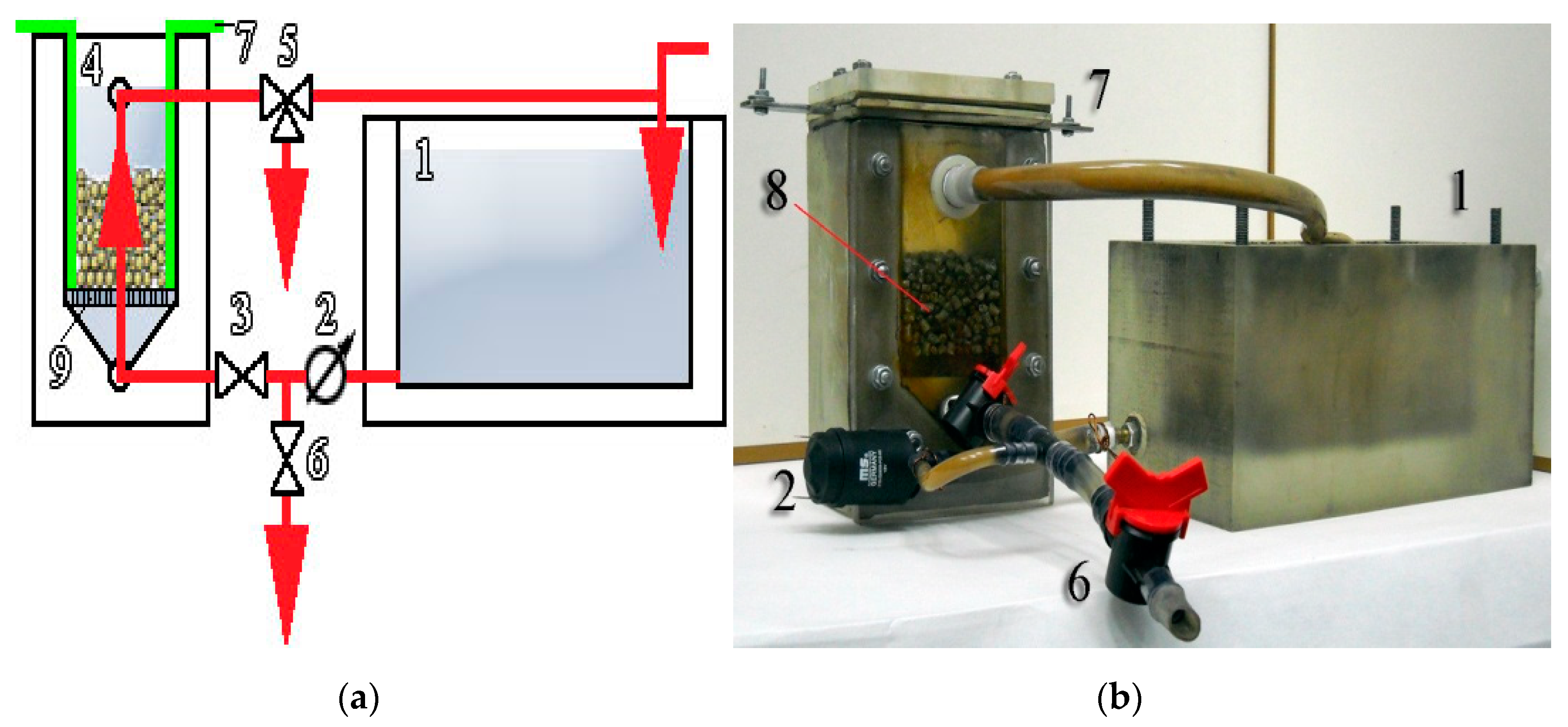
The experimental reactor (Figure 5a, position 4) is made in the form of a rectangular hollow parallelepiped with flat steel electrodes (position 7), a perforated bottom (position 9), and a prism-shaped cavity under it. The tank (position 1) was filled with galvanic wastewater. The shut-off valve (position 6) was set to the turned-off position. When the pump (position 2) was turned on by a valve (position 3), the required volumetric flow rate of the liquid was established. The volume of the reactor is about 20 dm3, and the tested hydraulic retention times is about 300 s.
The galvanic wastewater entered the reactor passing through the holes of the perforated bottom, then through the metal loading layer (Figure 5b, position 8), in which multichannel spark discharges between metal granules formed at a given frequency. After that, through the nozzle, depending on the position of the valve (Figure 5a, position 5), the treated galvanic wastewater was poured into a container for the next analysis or returned to a repeated treatment cycle.
The determination of the content of heavy metals in the start and treated water was carried out in accordance with the current regulatory documents [52,53,54]. The hydrogen index (pH) of the start galvanic wastewaters and the treated liquid was measured by an Ionomer I-160 M.
The efficiency of the galvanic wastewaters treatment process was studied by varying the specific processing energy, the amount of stored energy, the pulse parameters, and the height of the metal load.

3. Results

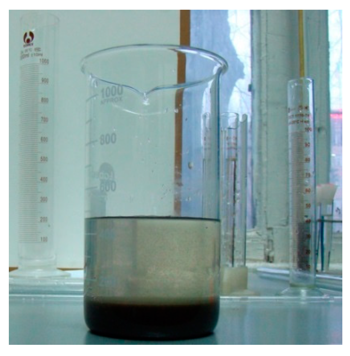
The peculiarity of the experiment was that the electro erosion powder, which is formed during the electrospark process, is a coagulant. At volumetric fluid flow rates of 50 dm3/h, the system is in a suspended state. Auto sedimentation is observed (Figure 6) immediately after sampling (order of time: min). The color of the liquid was changed from light yellow to transparent. To visualize the effect of self-sedimentation, i.e., the formation of a large amount of electro erosion powder, the treatment was performed for a long time: about 3 h with looping of the fluid flow.
A sampling of wastewater from the reactor was carried out immediately after the end of each treatment. The wastewater was filtered using F-type filter paper. The volume of the sample filtrate for chemical analysis was 1.5 dm3.
The content of heavy metal ions in wastewater generated by the enterprise is not constant. Therefore, for all through treatments, one source material was used: sewage selected at treatment plants (Table 1).
The study also used another concentrated content of harmful substances source material (Table 1, second line) of the same galvanic origin, which was selected at treatment plants at other times. So, the source material for treatment is natural sewage of galvanic production from different streams of a machine-building enterprise.
The choice of the range of variation of parameters and processing schemes is based on the following assumptions. The specific energy is varied taking into account the data given in paper [17], which relates to the purification from highly concentrated solutions of heavy metal ions (from 8500 mg/dm3—total content of heavy metals and up to 600 mg/dm3 Cr6+, respectively) with high-voltage electric discharges in reactors with granular metal loading in a column electrocoagulator.
We used data on the electrospark method for producing highly dispersed powders of metals and alloys to select the value of the pulse energy (Wp) [50]. This process can be implemented with pulse frequencies (f) up to several kHz using capacitor banks with capacities from 10 to 120 μF. For research, we chose a capacitance corresponding to the middle of the range: 65 uF. The charging voltage was determined experimentally. To do this, we first set the charging voltage (U0), which corresponds to the extremum of the relative energy release in the interelectrode gap of the dispersion reactor to the stored energy of the capacitor bank.
η W = W p W 0 = 0 τ 1 i ( t ) u ( t ) d t W 0
where Wp is the energy that is released in the interelectrode gap of the reactor during one discharge pulse, J; W0 = CU
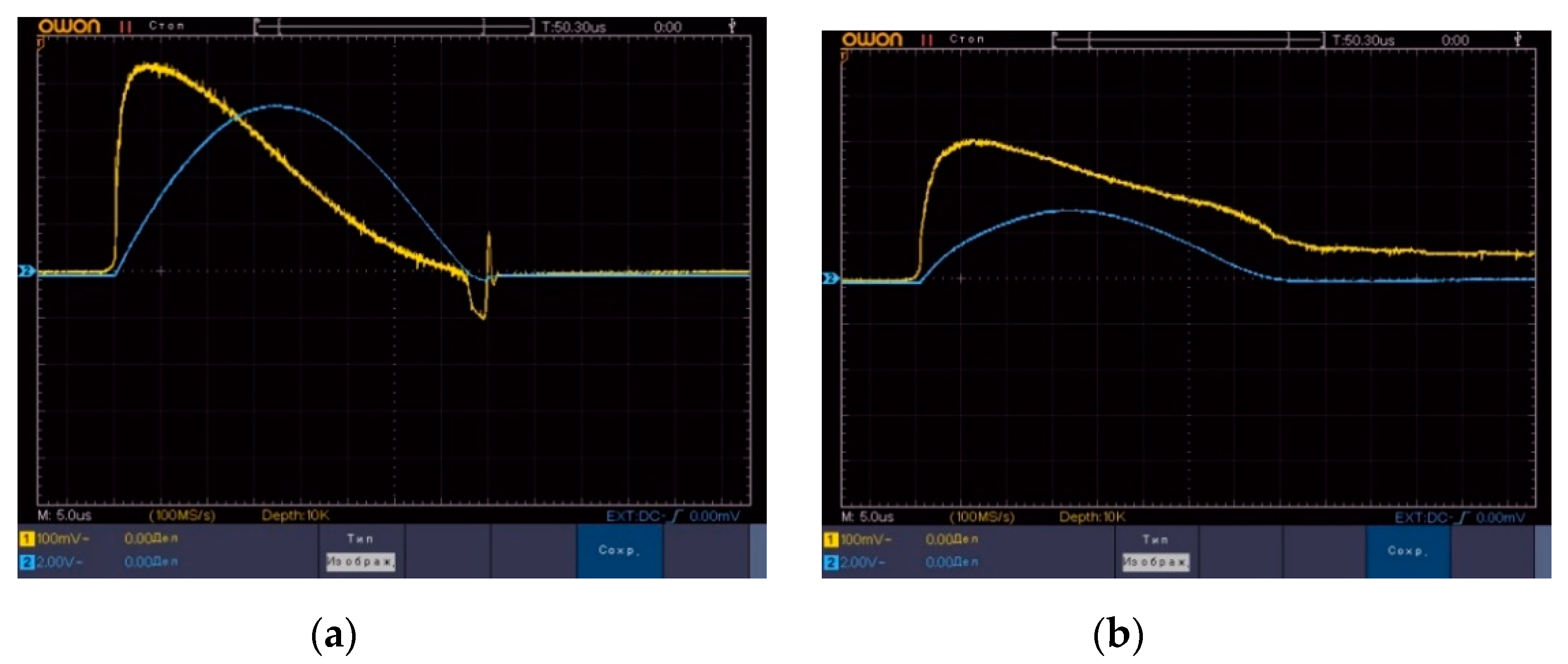
02/2 is the energy stored by the capacitor bank to the beginning of the discharge, J; and τ1, i(t), and u(t) are the discharge time, discharge current (time dependence), and the voltage on the electrode gap (time dependence), respectively, which are calculated from the results of oscillography (Figure 7).
Further increase of the charging voltage translates the discharge into the oscillating phase, which is very rarely used in the implementation of the electro spark method, both for fundamental reasons and for technical reasons, as there is a need to use a high-frequency diode connected to the switch. The maximum value of ηW can be equal to 0.9–0.95 (Figure 7a). However, this situation is idealized, and its practical implementation requires constant adaptive regulation of the charge voltage level. As part of the study, this does not allow adequately controlling the energy losses in the elements of the discharge circuit, as well as the specific energy consumption for galvanic purification. To reliably assess the effectiveness of galvanic purification cleaning, the value of ηW was brought to the values of 0.8–0.85 (Figure 7b) due to the gradual decrease of the charging voltage. The conditions ηW approximately 0.8–0.85 corresponded to the values of Wp = 3.6 J and W0 = 4.5 J, which were chosen for experimental treatments of galvanic discharges. The efficiency of galvanic purification in the process of changing the specific processing energy is presented in Table 2. The concentration of heavy metals in the initial solution is less than the maximal permissible concentrations (MPC) for the region (Ukraine). So, the concentration of Zn2+, Cr6+ + Cr3+, and Cu2+ ions are 0.26 mg/dm3, 1.27 mg/dm3, and 0.06 mg/dm3 (MPC are 1 mg/dm3, 2.5 mg/dm3, and 2.5 mg/dm3), respectively. A comparative analysis of the treatment results with the specific treatment energy change is given in Table 3, where Δn is the decrease in the concentration of metal ions after electrospark treatment relative to the initial concentration in the source wastewater, in absolute units, mg/dm3; n is the number of the processing option; Krn is a multiplicity of purification, i.e., the ratio of the initial concentration of heavy metal ions to the concentration after treatment.
Analysis of the purification results showed that for all metals, their concentration was reduced to values below the MPC.
During the study of the galvanic purification effectiveness, when changing the pulse processing parameters, experiments were performed with long and short-term pulses with different power levels. Pulse parameters are the duration and maximum values of the power of the bit pulse. For high-voltage discharges in water, the approach of dividing them into two groups is widespread, each of which is characterized by a set of common features of the introduction of electrical energy into the spark load. These are short-term and long-term discharges.
The condition of division is the duration of the first half-cycle of the discharge current: up to 40 μs and more than 40 μs, respectively. Changing the pulse processing parameters under the condition of fixing the energy of a single discharge pulse leads to redistribution between the granules’ material. As a result of heating under the action of the discharge current, the material of the granules passes into the gas and liquid phases with subsequent condensation. There is a redistribution of the micro- and nanopowder of the metal formed in the liquid, by dispersion, morphology, and other features, which leads to a change of its coagulation properties.
The characteristics of the electric discharge plasma formed between the granules also change. Fixation of the total galvanic processing energy when changing the pulse parameters of the discharge allows you to set more efficient parameters for purification efficiency, namely: short-term discharge pulses with a higher maximum power, or longer with a lower maximum power.
The pulse processing parameters in the bit circuit were increased in 25 times in relation to its inductance. The values of Wp and W0 have been left as above (3.6 J and 4.5 J, respectively). So, the discharge duration is increased from 38 to 200 μs.
The effectiveness of galvanic purification when changing the pulse processing parameters is given in Table 4. As can be seen from the data on the concentrations of heavy metal ions after treatment (Table 4), changes in the efficiency of purification with a significant change in the pulse parameters did not occur.
This conclusion has practical value. The change in the pulse parameters of the treatment due to the increase in inductance has almost no effect on the purification efficiency. There is a possibility of a serial (in the electrical sense) connection of several purification reactors to one source of discharge current pulses without any loss of purification efficiency. The “softening” of the working conditions of the electric equipment can promote an increase of its resource, reducing the intensity and regulation of the frequency spectrum of electromagnetic interference, etc.
Note that by visual signs, the change in the temperature of the discharge plasma between the granules occurred (the color temperature changed). This aspect requires further research using high-speed photo recording and may be useful in determining priority mechanisms for electro spark cleaning.
The effectiveness of processing when changing the frequency of discharge pulses was studied by fixing the volumetric speed of the fluid flow. To solve this problem, two galvanic treatments were performed. The volumetric flow rate of the liquid was recorded at 50 dm3 h. Two frequencies of discharge pulses were established, which were correlated as 1/2. The first frequency is the same at which the results described above are obtained. The specific processing energy was chosen between two values of 130 and 65 kJ/dm3 (namely, 90 kJ/dm3) and was also recorded. The energy released in the interelectrode gap of the reactor during one discharge pulse and the stored energy remained unchanged: Wp = 3.6 J and W0 = 4.5 J (Table 5 and Table 6).
The results of the experiments (Table 5 and Table 6) indicate the possibility of increasing the productivity of galvanic discharge cleaning by the electrospark method by increasing the discharge pulse frequency. Such an increase is possible up to certain limit values and has certain limitations on the initial concentrations of the pollutant. Addressing these issues requires further research. It should be noted that some differences in performance are still present and relate to the deep purification of galvanic discharge from zinc ions in the region of low concentrations.
Next, we investigated the effectiveness of galvanic wastewater purification when changing the scheme of implementation of the fluid flow (longitudinal/transverse). To realize the longitudinal fluid flow, the condition h > l was observed, i.e., the fluid flow was realized along with the larger size of the metal loading layer. To organize the transverse flow of the liquid, the height of the layer of granules was reduced to comply with the condition h ≤ l/2 (Table 7 and Table 8).
Analysis of the results (Table 7 and Table 8) shows that the length of the liquid path through an active layer (the layer where the discharge plasma is formed between the granules and the processes phase transitions of the granule material occur) may be important (in this case, the length is h). That is, the presence of micro- and submicron-powder coagulants in the liquid is not the only purification mechanism. This circumstance is especially related to the processes of zinc and copper ions.
The conclusion about technological implementation is obvious. Increasing the height of the layer of granules arbitrarily is not possible. In the lower layers of granules, under the action of weight loading, spark channels cease to be formed, the welding of granules occurs more often, and energy losses increase. It is necessary to divide one reactor into several sections located one above the other. This is possible through the use of dielectric perforated jumpers mounted horizontally. In each section, the maximum possible height of a layer of granules has been provided.
The influence of the energy in a pulse on the degree of galvanic wastewater purification at a fixed specific energy (W = 130 kJ/dm3) and a slight change in the pulse duration (from 38 to 40 μs) is presented in Table 9.
As can be seen from Table 9, the increase in energy in the pulse only leads to deterioration in the purification of metal ions in the low concentration area. Since a multiple increase in the capacity of the capacitor bank leads to such problems, the increase in energy in the pulse in this way is impractical for solving the problems of galvanic purification.

4. Discussion

Analysis and comparison of the Table 10 data allow drawing the following conclusions. Flow-through treatment of galvanic wastewaters to MPC standards using the electrospark method, granular metal loading, and a low voltage (up to 1000 V) source of discharge currents is possible and technologically feasible. This electrospark method allows achieving high results of wastewater treatment from galvanic industries from heavy metals. The achieved degree of galvanic wastewaters purification in the case of moderate concentrations of heavy metal ions (Zn2+, ΣCr, Cu2+) is higher, sometimes by several times in comparison with the MPC standards in different countries of the world.
The main influence on the degree of galvanic purification, with the correct choice of the parameters of the discharge pulse, has specific processing energy. For moderate concentrations of pollutants, it may be less than 65 kJ/dm3. Other parameters are a tool for purification processes or a means of regulating the modes of operation of electrical equipment.
The issues of checking the effectiveness of galvanic purification at industrial frequencies of discharge pulses are promising, i.e., 1 kHz in the flow (single-flow) implementation to identify threshold, critical, undesirable, or positive effects. Such effects will occur at pulse frequencies above 100 Hz. The introduction of the method into the technological process at lower frequencies is impractical from the standpoint of productivity.

5. Conclusions

Research has been carried out on the purification of multicomponent galvanic wastewaters by the electric spark method using combined metal loading (Fe, Al) and low-voltage (up to 1000 V) equipment. It is shown that the degree of purification depends on the specific energy and the height of the metal loading of the reactor, and it weakly depends on the pulse energy and the speed of its input. The electrospark method gives positive results in relation to improving water quality. The main influence on the degree of galvanic wastewaters’ purification under the conditions of choosing the parameters of the discharge pulse is the specific energy, which at moderate concentrations of pollutants can be less than 65 kJ/dm3, and metal loading height. The concentrations of heavy metals (Zn2+, Cr6++Cr3+, Cu2+) in the treated water are significantly lower than their MPC values regulated in different countries. The electrospark method is effective in terms of accelerating the rate of wastewater treatment from heavy metals. The solution to the issues of checking the effectiveness of wastewater treatment by the electrospark method under the conditions of real production is promising.

Author Contributions

Conceptualization, S.P. and A.Y.; methodology, S.P. and A.Y.; software, S.P., A.Y. and O.M.; validation, S.P. and A.Y.; formal analysis, V.P. and O.P.; investigation, S.P.; resources, S.P. and A.Y.; data curation, S.P., A.Y. and O.M.; writing—original draft preparation, O.M.; writing—review and editing, V.P., O.P.; visualization, O.M. and V.P.; supervision, V.P., O.P.; project administration, O.P. All authors have read and agreed to the published version of the manuscript.

Funding

This research received no external funding.

Conflicts of Interest

The authors declare no conflict of interest.

References

  1. Bharti, N.; Katyal, D. Water quality indices used for surface water vulnerability assessment. Int. J. Environ. Sci. 2011, 2, 154–173. [Google Scholar]
  2. Mitryasova, O.; Pohrebennyk, V. Integrated environmental assessment of the surface waters pollution: Regional aspect. In Proceedings of the International Multidisciplinary Scientific GeoConference SGEM, Vienna, Austria, 27–29 November 2017; Volume 33, pp. 235–242. [Google Scholar]
  3. Barakat, M.A. New trends in removing heavy metals from industrial wastewater. Arab. J. Chem. 2011, 4, 361–377. [Google Scholar] [CrossRef] [Green Version]
  4. Mitryasova, O.; Koszelnik, P.; Gruca-Rokosz, R.; Smirnov, V.; Smirnova, S.; Bezsonov, Y.; Zdeb, M.; Ziembowicz, S. Features of heavy metals accumulation in bottom sediments of the Southern Bug Hydroecosystem. J. Ecol. Eng. 2020, 21, 51–60. [Google Scholar] [CrossRef]
  5. Pohrebennyk, V.; Mitryasova, O.; Klos-Witkowska, A.; Dzhumelia, E. The role of monitoring the territory of industrial mining and chemical complexes at the stage of liquidation. In Proceedings of the International Multidisciplinary Scientific GeoConference SGEM, Vienna, Austria, 27–29 November 2017; Volume 33, pp. 383–390. [Google Scholar]
  6. Mitryasova, O.; Pohrebennyk, V.; Cygnar, M.; Sopilnyak, I. Environmental natural water quality assessment by method of correlation analysis. In Proceedings of the International Multidisciplinary Scientific GeoConference Surveying Geology and Mining Ecology Management, SGEM, Albena, Bulgaria, 30 June–6 July 2016; Volume 2, pp. 317–324. [Google Scholar]
  7. Efimova, N.; Krasnopyorova, A.; Yuhno, G.; Scheglovskaya, A. Sorption of heavy metals by natural biopolymers. Adsorpt. Sci. Technol. J. 2017, 35, 7–8. [Google Scholar] [CrossRef]
  8. Pohrebennyk, V.; Dzhumelia, E.; Korostynska, O.; Mason, A.; Cygnar, M. X-Ray fluorescent method of heavy metals detection in soils of mining and chemical enterprises. In Proceedings of the 9th International Conference on Developments in eSystems Engineering, DeSE 2016, Liverpool, UK, 31 August–2 September 2017; pp. 323–328. [Google Scholar]
  9. Matukhno, E.; Belokon, K.; Shatokha, V.; Baranova, T. Ecological aspects of sustainable development of metallurgical complex in Ukraine. Procedia Environ. Sci. Eng. Manag. 2019, 6, 671–680. [Google Scholar]
  10. Mitryasova, O.; Pohrebennyk, V. Hydrochemical indicators of water system analysis as factors of the environmental quality state. In Sustainable Production: Novel Trends in Energy, Environment and Material Systems. Studies in Systems, Decision and Control; Królczyk, G., Wzorek, M., Król, A., Kochan, O., Su, J., Kacprzyk, J., Eds.; Springer: Cham, Switzerland, 2020; Volume 198, pp. 91–104. [Google Scholar]
  11. Pohrebennyk, V.; Petryk, A. The degree of pollution with heavy metals of fallow soils in rural administrative units of Psary and Płoki in Poland. In Proceedings of the 17th International Multidisciplinary Scientific GeoConference, SGEM, Albena, Bulgaria, 29 June–5 July 2017; Volume 17, pp. 967–974. [Google Scholar]
  12. Kulskij, L. Spravochnik po svojstvam, metodam analiza i ochistke vody‘ v dvukh chastyakh (Handbook on the Properties, Methods of Analysis and Water Purification in Two Parts); Naukova dumka: Kiev, Ukraine, 1980; Volume 2, p. 630. (In Russian) [Google Scholar]
  13. Coagulation and Flocculation in Water and Wastewater Treatment. Available online: https://www.iwapublishing.com/news/coagulation-and-flocculation-water-and-wastewater-treatment (accessed on 10 June 2020).
  14. Filatova, E.; Soboleva, A. Intensifikacziya e lektrokoagulyaczionnogo metoda ochistki stochny‘kh vod gal‘vanicheskogo proizvodstva (Intensification of the electrocoagulation method of wastewater treatment of galvanic production). Int. Res. J. 2012, 5, 127–128. (In Russian) [Google Scholar] [CrossRef]
  15. Filatova, E.; Soboleva, A.; Dudarev, V.; Pomazkina, O. Elektrokoagulyaczionnaya ochistka stochny‘kh vod gal‘vanicheskogo proizvodstva ot ionov nikelya (Electrocoagulation wastewater treatment of galvanic production from nickel ions). Mod. Probl. Sci. Educ. 2012, 2. Available online: http://www.science-education.ru/ru/article/view?id=5860 (accessed on 10 June 2020). (In Russian).
  16. Solozhenkin, P.; Nebera, M.; Zubulis, A. Teoreticheskie aspekty i prakticheskoe ispol‘zovanie gal‘vanokhimicheskogo proczessa v ochistke tekhnogenny‘kh vod (Theoretical aspects and practical use of the galvanochemical process in the treatment of industrial waters). Min. Inf. Anal. Bull. 2003, 6, 201–205. (In Russian) [Google Scholar]
  17. Prakash, N.B.; Sockan, V.; Jayakaran, P. Waste water treatment by coagulation and flocculation. Int. J. Eng. Sci. Innov. Technol. (IJESIT) 2014, 3, 479–484. [Google Scholar]
  18. Bratby, J. Coagulants in Coagulation and Flocculation in Water and Wastewater Treatment, 2nd ed.; IWA Publishing: London, UK, 2006; pp. 50–68. [Google Scholar]
  19. Bazrafshan, E.; Mohammadi, L.; Ansari-Moghaddam, A.; Mahvi, A.H. Heavy metals removal from aqueous environments by electrocoagulation process—A systematic review. J. Environ. Health Sci. Eng. 2015, 13, 74. [Google Scholar] [CrossRef] [Green Version]
  20. Tran, T.-K.; Leu, H.-J.; Chiu, K.-F.; Lin, C.-Y. Electrochemical treatment of heavy metal-containing wastewater with the removal of COD and heavy metal ions. J. Chin. Chem. Soc. 2017, 64, 493–502. [Google Scholar] [CrossRef]
  21. Nouri, J.; Mahvi, A.H.; Bazrafshan, E. Application of electrocoagulation process in removal of zinc and copper from aqueous solutions by aluminum electrodes. Int. J. Environ. Res. 2010, 4, 201–208. [Google Scholar]
  22. Rincon, G.J.; Motta, E.J.L. Simultaneous removal of oil and grease, and heavy metals from artificial bilge water using electrocoagulation/flotation. J. Environ. Manag. 2014, 144, 42–50. [Google Scholar] [CrossRef]
  23. Chaturvedi, S.I. Mercury removal using Al-Al electrodes by electrocoagulation. IJMER 2013, 3, 109–115. [Google Scholar]
  24. Shafaei, A.; Pajootan, E.; Nikazar, M.; Arami, M. Removal of Co2+ from aqueous solution by electrocoagulation process using aluminum electrodes. Desalination 2011, 279, 121–126. [Google Scholar] [CrossRef]
  25. Bazrafshan, E.; Mahvi, A.H.; Naseri, S.; Mesdaghinia, A.R. Performance evaluation of electrocoagulation process for removal of chromium6+ from synthetic chromium solutions using iron and aluminum electrodes. Turk. J. Eng. Environ. Sci. 2008, 32, 59–66. [Google Scholar]
  26. Mahvi, A.H.; Bazrafshan, E. Removal of cadmium from industrial effluents by electrocoagulation process using aluminum electrodes. World Appl. Sci. J. 2007, 2, 34–39. [Google Scholar]
  27. Gholami Borujeni, F.; Mahvi, A.H.; Nejatzadeh-Barandoozi, F. Removal of heavy metal ions from aqueous solution by application of low cost materials. Fresenius Environ. Bull. 2013, 22, 655–658. [Google Scholar]
  28. Kobya, M.; Demirbas, E.; Sozbir, M. Depolarization of aqueous reactive dye Remazol Red 3B by electrocoagulation. Color. Technol. 2010, 126, 282–288. [Google Scholar] [CrossRef]
  29. Pociecha, M.; Lestan, D. Using electrocoagulation for metal and chelant separation from washing solution after EDTA leaching of Pb, Zn and Cd contaminated soil. J. Hazard. Mater. 2010, 174, 670–678. [Google Scholar] [CrossRef]
  30. Saini1, S.; Katnoria, J.K.; Kaur, I. A comparative study for removal of cadmium(II) ions using unmodified and NTA-modified Dendrocalamus strictus charcoal powder. J. Environ. Health Sci. Eng. 2019, 17, 259–272. [Google Scholar] [CrossRef]
  31. Mansoorian, H.J.; Rajabizadeh, A.; Bazrafshan, E.; Mahvi, A.H. Practical assessment of electrocoagulation process in removing nickel metal from aqueous solutions using iron-rod electrodes. Desalin. Water Treat. 2012, 44, 29–35. [Google Scholar] [CrossRef]
  32. Kabdaşlı, I.; Vardar, B.; Alaton, A.I.; Tünay, O. Effect of dye auxiliaries on color and COD removal from simulated reactive dye bath effluent by electrocoagulation. Chem. Eng. J. 2009, 148, 89–96. [Google Scholar] [CrossRef]
  33. Hunsom, M.; Pruksathorn, K.; Damronglered, S.; Vergnes, H.; Duverneuil, P. Electrochemical treatment of heavy metals (Cu2+, Cr6+, Ni2+) from industrial effluent and modeling of copper reduction. Water Res. 2005, 39, 610–616. [Google Scholar] [CrossRef] [PubMed]
  34. Kamaraj, R.; Vasudevan, S. Evaluation of electrocoagulation process for the removal of strontium and cesium from aqueous solution. Chem. Eng. Res. Des. 2015, 93, 522–530. [Google Scholar] [CrossRef]
  35. Malakootian, M.; Yousefi, N.; Fatehizadeh, A. Survey efficiency of electrocoagulation on nitrate removal from aqueous solution. Int. J. Environ. Sci. Technol. 2011, 8, 107–114. [Google Scholar] [CrossRef]
  36. Mahvi, A.H.; Ebrahimi, S.J.A.; Mesdaghinia, A.; Gharibi, H.; Sowlat, M.H. Performance evaluation of a continuous bipolar electrocoagulation/electrooxidation–electroflotation (ECEO–EF) reactor designed for simultaneous removal of ammonia and phosphate from wastewater effluent. J. Hazard. Mater. 2011, 192, 1267–1274. [Google Scholar] [CrossRef]
  37. Apaydin, K.U.; Gonullu, M.T. An investigation on the treatment of tannery wastewater by electrocoagulation. Glob. Nest J. 2009, 11, 546–555. [Google Scholar]
  38. Bazrafshan, E.; Ownagh, K.; Mahvi, A.H. Application of electrocoagulation process using iron and aluminum electrodes for fluoride removal from aqueous environment. J. Chem. 2012, 9, 2297–2308. [Google Scholar] [CrossRef] [Green Version]
  39. Mohamed-Hasnain, I.; Ezerie, H.E.; Zubair, A.; Saleh, F.M.; Shamsul, R.; Mohamed, K. Boron removal by electrocoagulation and recovery. Water Res. 2014, 51, 113–123. [Google Scholar]
  40. Jung, K.W.; Hwang, M.J.; Park, D.S.; Ahn, K.H. Combining fluidized metalimpregnated granular activated carbon in three-dimensional electrocoagulation system: Feasibility and optimization test of color and COD removal from real cotton textile wastewater. Sep. Purif. Technol. 2015, 146, 154–167. [Google Scholar] [CrossRef]
  41. Holt, P.K.; Barton, G.W.; Mitchell, C.A. Deciphering the science behind electrocoagulation to remove clay particles from water. Water Sci. Technol. 2004, 50, 177–184. [Google Scholar] [CrossRef]
  42. Adjeroud, N.; Dahmoune, F.; Merzouk, B.; Leclerc, J.P.; Madani, K. Improvement of electrocoagulation–electroflotation treatment of effluent by addition of Opuntia ficus indica pad juice. Sep. Purif. Technol. 2015, 144, 168–176. [Google Scholar] [CrossRef]
  43. Bazrafshan, E.; Biglari, H.; Mahvi, A.H. Phenol removal by electrocoagulation process from aqueous solutions. Fresenius Environ. Bull. 2012, 21, 364–371. [Google Scholar]
  44. Adhoum, N.; Monser, L.; Bellakhal, N.; Belgaied, J.E. Treatment of electroplating wastewater containing Cu2+, Zn2+ and Cr6+ by electrocoagulation. J. Hazard. Mater. 2004, 112, 207–213. [Google Scholar] [CrossRef] [PubMed]
  45. Levchenko, V. Elektroimpulsnyj metod kompleksnoj pererabotki materialov (Electropulse method of complex processing of materials). Mech. Eng. Probl. 1992, 38, 78–86. (In Russian) [Google Scholar]
  46. Yushhishina, A.; Zubenko, A.; Petrichenko, L.; Malyushevskaya, A.; Smalko, A.; Khajnaczkij, S.; Kovalenko, V. Sedimentaczionnye kharakteristiki elektrorazryadnykh gidroksidov alyuminiya i zheleza (Sedimentation characteristics of electric discharge aluminum and iron hydroxides). Electron. Mater. Proc. 2005, 3, 46–50. (In Russian) [Google Scholar]
  47. Khajnaczkij, S.; Zubenko, A.; Smalko, A.; Kreshhenko, V.; Kovalenko, V. Issledovaniya kompleksnoj ochistki vody ot ionov tyazhelykh metallov pri vysokovoltnykh elektricheskikh razryadakh v reaktorakh s granulirovannoj metallozagruzkoj (Studies of complex water purification from heavy metal ions during high-voltage electric discharges in reactors with granular metal loading). Electron. Mater. Proc. 2005, 6, 53–58. (In Russian) [Google Scholar]
  48. Tang, S.K. The Process Fundamentals and Parameters of Electro-spark Deposition. Master’s Thesis, University of Waterloo, Waterloo, ON, Canada, 2009. [Google Scholar]
  49. Shcherba, A.; Suprunovskaya, N.; Petrichenko, S. Dynamic Processes in Electric Discharge Installations: Monograph; Press Office NAS of Ukraine: Kyiv, Ukraine, 2017. Available online: http://www.nas.gov.ua/EN/Book/Pages/default.aspx?BookID=0000011533 (accessed on 10 June 2020). (in Russian)
  50. Petrichenko, S.; Listovskij, D.; Kuskova, N. Stabilizacziya razryadnykh impulsov i osobennosti soglasovaniya iskrovoj nagruzki pri elektroerozionnom dispergirovanii metallicheskikh i grafitovykh granul v zhidkosti (Stabilization of discharge pulses and peculiarities of matching spark load during electroerosive dispersion of metal and graphite granules in a liquid). Electron. Mater. Proc. 2016, 2, 8–13. (In Russian) [Google Scholar]
  51. Zakharchenko, S.; Kondratenko, I.; Perekos, A.; Zaluczkij, V.; Kozyrskij, V.; Lopatko, K. Vliyanie dlitelnosti razryadnykh impulsov v sloe granul zheleza na razmery i strukturno-fazovoe sostoyanie ego elektroerozionnykh chasticz (Influence of the duration of discharge pulses in a layer of iron granules on the size and structural phase state of its electroerosive particles). East. Eur. J. Adv. Technol. 2012, 6, 66–72. (In Russian) [Google Scholar]
  52. MVV No 081/12 0178 05: Poverkhnevi, Pidzemni ta Zvorotni Vodi. Metodika Vikonannya Vimiryuvan Masovoyi Konczentracziyi Nikelyu Fotokolorimetrichnim Metodom (Surface, Groundwater and Return Water. Method of Performing Measurements of Mass Concentration of Nickel by Photocolorimetric Method). 2005. Available online: http://online.budstandart.com/ua/catalog/doc-page?id_doc=29902 (accessed on 10 June 2020). (In Ukrainian).
  53. MVV No 081/12 0173 05: Poverkhnevi, Pidzemni‘ ta Zvorotni Vodi. Metodika Vikonannya Vimiryuvan Masovoyi Konczentracziyi Czinku Fotokolorimetrichnim Metodom (0.005–1.0 мг/дм3) (Surface, Groundwater and Return Water. Method of Performing Measurements of Mass Concentration of Zinc by Photocolorimetric Method (0.005–1.0 мг/дм3). 2005. Available online: http://online.budstandart.com/ua/catalog/doc-page?id_doc=76456 (accessed on 10 June 2020). (In Ukrainian).
  54. MVV No 081/12-0114-03: Poverkhnevi, Pidzemni ta Zvorotni Vodi. Metodika Vikonannya Vimiryuvan Masovoyi Konczentracziyi Khromu Zagalnogo, Khromu(VI) ta Khromu(III) Ekstrakczijno-Fotokolorimetrichnim Metodom z Difenilkarbazidom (Surface, Groundwater and Return Water. Methods of Measurement of Mass Concentration of Chromium total, Chromium(VI) and Chromium(III) by Extraction-Photocolorimetric Method with Diphenylcarbazide). 2003. Available online: http://online.budstandart.com/ua/catalog/doc-page.html?id_doc=76440 (accessed on 10 June 2020). (In Ukrainian).
Figure 1. A schematic diagram of the discharge–pulse treatment of the liquid. 1—step-up transformer; 2—diode bridge; 3—capacitor; 4—electrodes; 5—treated fabric; 6—cylindrical mesh; 7—reactor vessel; 8—discharge zone; 9—liquid.
Applsci 10 05148 g001
Figure 2. A typical type of single electrospark.
Applsci 10 05148 g002
Figure 3. The appearance of metal-loading granules: (a) iron granules; (b) aluminum granules.
Applsci 10 05148 g003
Figure 4. The electrical circuit of the experimental low-voltage source of discharge currents.
Applsci 10 05148 g004
Figure 5. (a) The hydraulic scheme and (b) the appearance of the reactor.
Applsci 10 05148 g005
Figure 6. Deposition of electro erosion powder after sampling.
Applsci 10 05148 g006
Figure 7. Oscillograms of the discharge current (blue curve) and voltage on the interelectrode gap (yellow curve) for ηW ~ 0.95 (a) and ηW ~ 0.8 (b).
Applsci 10 05148 g007
Table 1. The content of heavy metal ions in the source wastewater (basic galvanic discharge).
pHColorZn2+, mg/dm3Cr3+ + Cr6+, mg/dm3Cu2+, mg/dm3
7.45light yellow0.261.270.06
6.00light yellow0.064.695.28
Table 2. The efficiency of galvanic purification in the process of changing the specific energy.
Specific Energy, kJ/dm3 Zn2+, mg/dm3Cr3+ + Cr6+, mg/dm3Cu2+, mg/dm3 pHColor
-0.261.270.067.45light yellow
13000.00020.0037.34colorless
650.0280.00230.0108.19colorless
Table 3. Comparison of purification results with changing the specific processing energy.
ValueZn2+Cr3+ + Cr6+Cu2+
Δ1 mg/dm30.261.270.06
Δ1 mg/dm30.231.270.05
Δ121.121.001.14
Kr1-635020
Kr29.295526
Table 4. The efficiency of galvanic purification in the process of changing the duration of pulse discharge.
Discharge Duration τ1, μs Zn2+, mg/dm3Cr3+ + Cr6+, mg/dm3Cu2+, mg/dm3 pHColor
-0.261.270.067.45light yellow
3800.00020.0037.34colorless
20000.00020.0037.33colorless
Table 5. The effectiveness of galvanic purification on changing the discharge pulse frequency.
Discharge Pulses FrequencyZn2+, mg/dm3Cr3+ + Cr6+, mg/dm3Cu2+, mg/dm3 pHColor
-0.261.270.067.45light yellow
00.00020.0078.00colorless
00.00700.0078.14colorless
Table 6. Comparison of purification results when changing the pulse frequency.
ValueZn2+Cr3+ + Cr6+Cu2+
Δ1 mg/dm30.241.270.05
Δ1 mg/dm30.191.270.05
Δ121.251.001.00
Table 7. The effectiveness of galvanic wastewater purification with changing the scheme of fluid flow implementation.
Fluid FlowZn2+, mg/dm3Cr3+ + Cr6+, mg/dm3Cu2+, mg/dm3 pHColor
-0.261.270.067.45light yellow
h > l0.000.00020.0037.34colorless
h ≤ l/20.150.00260.0157.84colorless
Table 8. Comparison of purification results with changing the scheme of fluid flow implementation.
ValueZn2+Cr3+ + Cr6+Cu2+
Δ1 mg/dm30.261.270.06
Δ1 mg/dm30.111.270.05
Δ122.361.001.20
Table 9. Influence of energy in a pulse on the degree of purification of galvanic wastewater.
The Stored Energy in a Pulse, JZn2+, mg/dm3Cr3+ + Cr6+, mg/dm3Cu2+, mg/dm3 pHColor
-0.261.270.067.45light yellow
4.50.000.00020.0037.34colorless
5.50.040.00170.0057.96colorless
Table 10. The maximal permissible concentrations (MPC) of the studied metals in galvanic wastewaters in different countries.
CountryZn2+, mg/dm3Cr3+, mg/dm3Cu2+, mg/dm3
USA1.48-2.07
EU0.500.500.50
Ukraine1.002.502.50
Belarus5.002.501.00
Russia2.001.000.50

