1. Introduction
1.1. The Strategy and Tactics of the Submarine Fleet in Modern Conditions
In the defense system of continental and island structure countries that have extensive coastlines, close attention is paid to the protection of maritime borders and water areas adjacent to land. Foremost is the development and improvement of anti-submarine warfare. Submarines play the leading role in the military struggle at sea. Possessing a combination of unique properties such as stealth, strength, mobility and capability for self-defense, submarines are capable of destructing onshore objects, missile submarines, groups of surface vessels and disrupting communications. The most vulnerable are the states having in their territory structures of crucial technologies, namely nuclear power plants, dams, hydroelectric power stations, production of ammunition, military hardware etc. Breaking defensive redoubts can be performed quite effectively by destruction of enterprises of the crucial technologies. With the advent of missile-carrying submarines (foremost of which are nuclear-powered ones) the Navy has become capable of making a strategic impact on the progress and outcome of contemporary war [
1].
When solving defense-specific tasks, as a rule, the primary importance is given to combating ballistic missile carrying submarines. A short flight time of ballistic missiles launched from submarines (about 15 min on a flight to the distance of 2800 km by standard trajectories and 7–8 min on a flight by depressed trajectories) may turn out to be insufficient for countermeasures taking by the defensive side.
In a number of cases, in order to provide for the combat qualities and tactical and technical characteristics of submersible vehicles, when solving intelligence and diversionary tasks, including for the tasks of aiming guided missiles, small-size submarines with a displacement from 200 kg up to 3.5 t are designed.
The above-listed evidences about the constant increase in the role of the submarine fleet in the military struggle show the broadening scope of tasks under present-day conditions. For this reason, great attention is paid to the issues of combating against submarines. Success in this combating will first depend on the timely detection, classification and determination of a underwater target’s location.
By the beginning of the twentieth century, the main design features of submarines had already been studied, the destructive capacity was properly evaluated and designing of submarines were coming to the state level. Developments of the ways to apply submarines in large-scale combat activities had begun.
The subsequent development of this class of vessels proceeded for the achievement of several main points: increase in the speed of motion both upon the positions of surfaced and submerged (upon maximum decrease in noisiness), increase in self-sustainment and range, and increase in the achievable depth of submersion [
2,
3,
4,
5].
The development of new types of submarines was running parallel in many countries. In the process of development, submarines obtained diesel electric power plants, periscopic observation systems and torpedo-artillery armament [
6]. Extensive application submarines were made in the First and then the Second World Wars.
The next important stage in the designing of submarines was the introduction of nuclear-power, which put steam turbines into operation. This type of main propulsion machinery was applied for the first time on USS Nautilus in 1955. Then, atomic submarines also appeared in fleets of USSR, United Kingdom and other countries.
At present, submarines are one of the most widespread and multipurpose class of vessels. Submarines perform a wide type of tasks from patrolling to nuclear deterrence.
It is recognized that contemporary submarines (Latin Submarina) of the class of “Ohio” are currently the most powerful weapon on the planet. They have a displacement of almost 19 thousand tons, two turbines 30
h.p. each, 24 ballistic missiles Trident II (D5) with a dozen warheads in each or 154 cruise missiles BGM-109 “Tomahawk” equipped with separable warheads with individual aiming. [
7,
8].
As of today, “Ohio” class SSBN (Ship Submarine Ballistic Nuclear) holds a world record on the number of missile pits, namely 24, and are justifiably considered to be one of the most flawless in their class.
High accuracy of the missiles “Trident II” allows for, along with land ICBM (Intercontinental Ballistic Missile), defeating all variety of high-strength targets of the type of launching silos and deepened command posts. A distance range of the “Trident” missile system allowed the “Ohio” class submarines to perform combat alerts in the Atlantic and Pacific Oceans in the dominance zones of their Navy, which provided them with a high tactic stability. A high level of effectiveness and comparatively low cost of SSBN maintenance armed with the missiles of “Trident-2” led to the Naval Strategic Forces being allowed to take up leading positions in the nuclear triad of the US [
9,
10,
11].
The major combat qualities of the present-day surface vessels include having a large cruising range, a powerful anti-aircraft warfare ability, and the capability to take on board unmanned and manned flying vehicles. Unfortunately, surface vessels are vulnerable to the anti-ship missiles and, moreover, too noticeable. Unlike them, submarines possess a high degree of stealth and better defense against missiles. However, the disadvantages include a slow speed of motion “below the periscope depth” and the impossibility of carrier-based aircraft usage [
12,
13].
The known ways for solving the problems of masking and limited visibility of submarines’ contours based on passive methods allow us to draw the conclusion that the most promising methods are still those based on the resonance phenomena of various physical and natural features [
14,
15,
16,
17,
18].
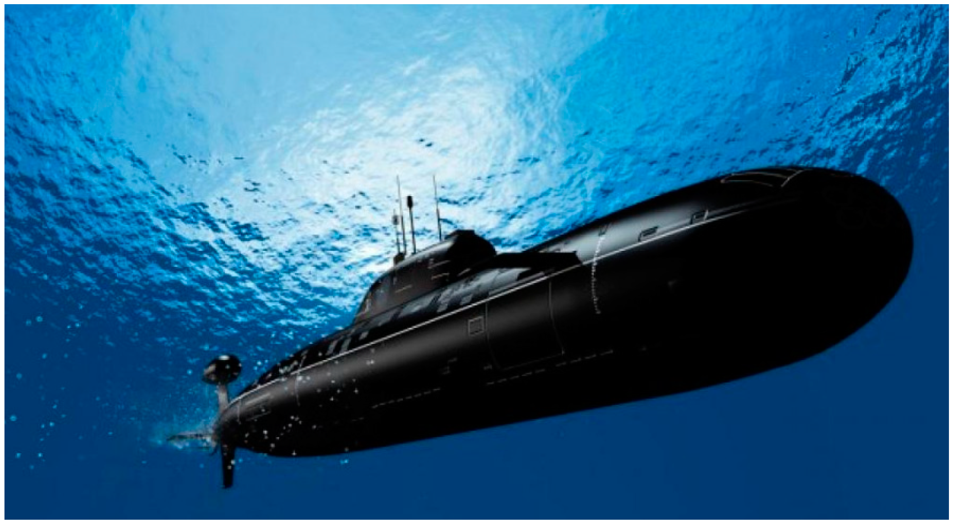
One of the most formidable military instruments in the world is the submarine. Submarines are not only ideally suited for covert operations, the destruction of enemy vessels and intelligence, but they are also capable of carrying nuclear weapons and exercising much pressure on the forces of a potential enemy (
Figure 1) [
9].
1.2. Interaction of an Unsteady Shock N-Wave with a Non-Deformable Shell of the Outer Hull of a Submarine
As has already been noted, in the countries with an extensive coastline, the protection system of its own borders inevitably include measures of antisubmarine warfare. Under present-day conditions, submarines play a leading role in the military struggle at sea. Possessing a combination of factors such as stealth, strength, mobility and capability for self-defense, submarines are capable of destructing onshore objects, missile submarines, groups of surface vessels and disrupting communications. With the advent of missile-carrying submarines, the foremost of which are nuclear-powered, the Navy have become capable of exerting strategic influence on the progress and outcome of contemporary war. It is the latter aspect that reveals the significance of combating against ballistic missile carrying submarines.
Thus, the issues of combating against submarines has been given increasingly more attention. The solution of this issue will first of all depend on the timely detection, classification and determination of an underwater target’s location. The solution of these tasks is mostly through hydroacoustic means. Echo ranging remains a reliable means for detecting an underwater target at present and in the foreseeable future.
The underkeel sonar station has some particular disadvantages, the most essential of which can be deemed the noises of the carrier vessel itself, the temperature jump’s interlayer and other less significant factors. Some considerable advantages over the underkeel sonar stations are the hydroacoustic stations with variable depth arrays (towed and lowered). A receiving–emitting acoustic array, in this case, is installed in the array container and is lowered or towed at a given depth. Vessels, helicopters, etc., can serve as a carrier. Stations with the variable depth arrays have great capabilities, since they operate under the layer of the temperature jump and in the zone of the underwater sonic channel.
The performance by a submarine in a combat mission depends on its invincibility. Without analyzing the integrity of the external pressure hull of the submarine and its subsequent destruction, let us only confine ourselves to the examination of the forced motion of a submarine, devoid of its own motion affected by the acoustic loads to the side of the sound wave spread.
The coefficient c (elasticity of the anchor extensions of the submarine, bow and stern anchor) makes it possible to choose the desired position and the given type of movement of the submarine. Using the coefficient c it is possible to set the stationary state and the required movement of the submarine. Using the coefficient c, it is also possible to introduce the necessary elastic qualities of the anchor chains, and form small vibrations of the submarine’s hull. Additionally, the coefficient c makes it possible to successfully counteract local intense undercurrents at depths below the periscope.
The object of the research is the interaction of the acoustic loads in the form of a shock with the submarine. The purpose of this research is to study the forced motion of a submersible vehicle affected by an acoustic wave. That is, the “stop the engine” mode.
The objective of research is finding out the nature of the translational motion of the hull of the submarine affected by an acoustic wave, or rather its limit value, as being the most important solution for combat missions.
In [
19], the problem of translational rectilinear motion of a cylinder is considered. Such a problem can be reduced to the problem of a steady flow around an immovable shell by an unlimited fluid flow. In accordance with the Lagrange theorem, this will allow us to consider the fluid flow as potential [
20]. Thus, it becomes possible to conduct research as a simpler case of a flat irrotational flow [
21].
These assumptions allowed us to formulate the boundary conditions in the form of equal to zero velocities of infinitely distant flow points, equality of the normal velocity components of the contour points and the particles of the medium in contact with them, as well as the continuity of the flow [
22].
The calculation model of the task is in the form of a thin plate with dimensions along the length and width that are equal to the longitudinal section of the outer hull of the submarine. For the convenience of calculations and obtaining results, we will use the well-developed methodology of the action of a plane wave on a thin plate [
15,
16]. However, in reality, the sound effect has the form of a diffuse field, which is when the propagation of sound in all directions is equally probable. To take this into account, in practice it is customary to perform averaging over Peris of the results, which were obtained in the analysis of the action of a plane wave, i.e.,
, where
is the angle between the wave vector and the normal to the plate.
Usually, integration is performed in the range from 0 upawards, which gives a closer coincidence of theoretical and experimental values. Therefore, we accept .
In the manuscript, the authors consider the external impact on the hull of a submarine in the form of a flat N-wave shock. This allows us to simplify the numerical analysis of the functional state of the submarine as a whole. The perturbed state of the hull of a submarine under conditions of deep-sea bombing can be a combination of a number of external disturbing factors. An underwater explosion from a bomb will generate, first of all, a powerful acoustic impact in the form of an N-wave. A bomb explosion will also create the following: power load on the external rigid body of the submarine; a water hammer; violation of the initial density of the liquid layers adjacent to the boat; and an extremely high temperature gradient of the environment. The authors limit themselves to the study of only one external disturbing effect, namely, a flat sound shock influence of an N-wave. In their calculations, the authors further simplify the model to the presence of overall mass symmetry in two mutually perpendicular planes of the submarine. The solution of the problem, in general, involves clarifying the independent influence of each of the disturbing factors on the external hard hull of the submarine, followed by analysis of the available or permissible mutual relationship between the marked disturbing force factors. A large number of cavitation bubbles of various sizes and densities serve as an excellent reference point for determining the location of a submarine. The study of this phenomenon allows one to use it to mask the submarine.
2. The Investigation of the Movement of Submarines under the Influence of an N-Wave Shock, Provided That the Outer Body of the Submarine is Absolutely Solid
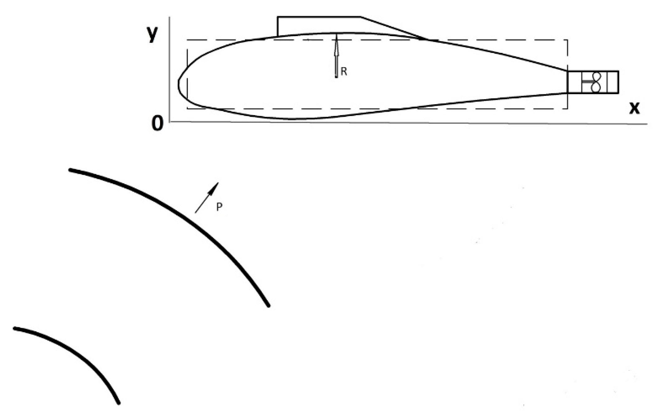
Let us consider the simplest case, when a plane wave affects the submarine’s external pressure hull with the shape of a circular cylinder (
Figure 2).
Let us establish the value of a forced translational motion of a submarine affected by the acoustic loads. Let us focus on the determination of the limit motion as being the most important for combat missions.
We will examine the translational motion of the absolutely rigid external hull of a submerged submarine into ideal liquid (upon absence of viscosity), calculated using a model of motion for the circular cross-section of the submarine (in the plane of frame) of radius
R [
12]:
where
—movement of the apparatus in the direction of the axis
;
—potential of incident wave propagating with speed c;
—potential of waves reflected from rigid fixed cylinder;
—potential of radiated waves caused by the motion of the cylinder; M is the mass of the submersible vehicle;
—the contour of its plane of the frame;
—direction of outer normal to
;
—fluid density;
—time.
With the direction of propagation of the wave, we associate the axis
the reference beginning of which coincides with the initially stationary apparatus (
Figure 2).
Let us analyze the endlessly extended motion of a submersible vehicle in all three dimensions, which is at the resting value of the liquid.
The study will be conducted for the case of ideal, in other words, not viscous liquid. It is worth noting, in advance, that many of the results, based upon such an assumption, can essentially differ from reality. First of all, it applies to the calculation of forces of resistance, which is experienced by translating bodies. The point is that the forces of internal friction or viscosity in a real liquid manifest, most essentially, in the thin layer directly adjacent to the surface of the submersible vehicle. Availability of even a minor viscosity can drastically change the field of velocities and, consequently, may serve as a change in a related field of hydrodynamic pressures around the object.
An exception is provided by the rectilinear and uniform motion of the vehicle in liquid. The created state of liquid movement will obviously be settled in regard to the axes related to the body. For calculation of the field of hydrodynamic pressure based on the Galilean principle of relativity of classical mechanics, let us select the fixed axes rigidly bound to the hull as the main ones. In other words, the objective of the translational rectilinear and uniform motion in liquid, which is in a state of complete rest at infinity, addresses the problem of steady flow around a motionless body by an endless flow of liquid, with boundlessly distant particles having equal velocities as per value and direction.
Let us consider how the simplest case of plane flow, wherein the vehicle is located in the shape of an endless extent cylinder with generatrices, which are perpendicular to the plane of its transverse flow. Let us limit the scope of the analyzed problems by studying the irrotational flow of incompressible liquid.
Boundary conditions. Dirichlet and Neumann problems. The simplest options of motion are given attention. Upon the condition of plane flow in the infinite mass of liquid being in the state of rest at infinity generated by the motion of the cylindrical body, the boundary conditions for the flow function , are in the following form:
- -
for the infinitely remote points of flow (velocity in these points shall be equal to zero)
- -
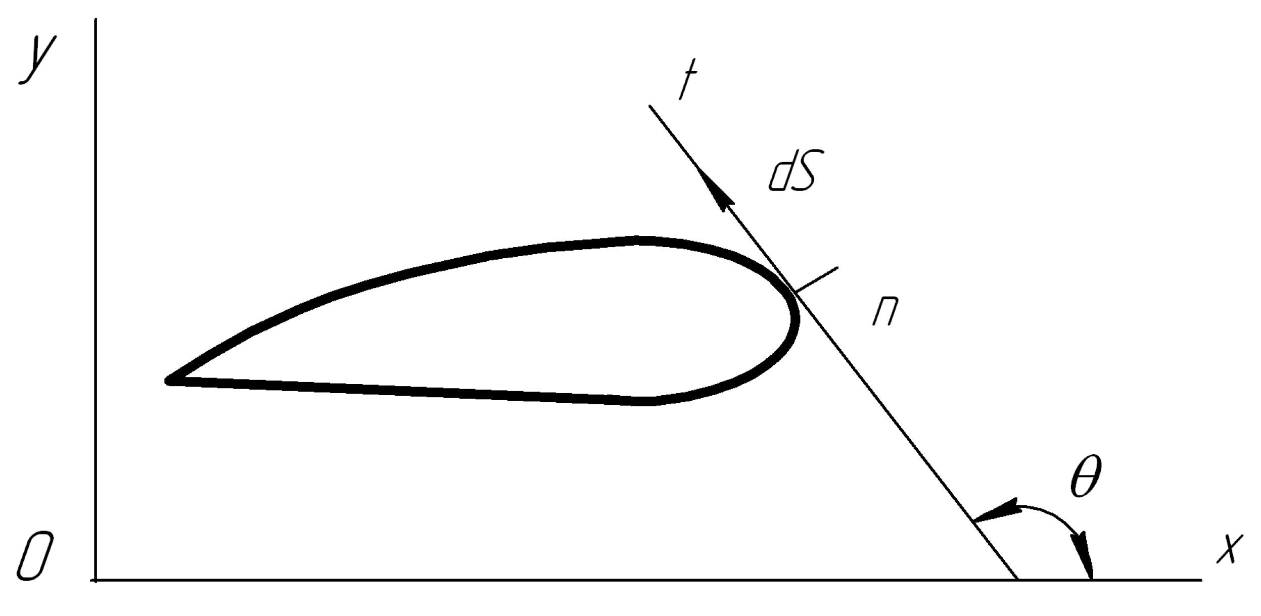
in each point of the vehicle’s contour that is moving, the components of the contour proper and velocities of the adjoining particles of liquid should match normal velocity (
Figure 3).
Take into consideration the following:
where
—angle between the element
of the flow line and axis
. Therefore,
The motionless contour itself should be in contact with the flow line. In this case, with requirements (2) and (3), the boundary condition is attached to the immovable contour is as follows:
If the vehicle is in motion, translationally with a velocity along the axis, then the condition has the following form:
After integration of this expression along the contour, upon the condition that for all points of the contour, we have the following:
For irrotational motion of incompressible liquid, let us present the known ratios as:
The translational circulationless flow of the ideal liquid, with the adopted assumptions about nonseparateness of the flow around the exercises, show no resultant pressure on the circular cylinder.
The nonseparateness equation:
proves that the function
will satisfy the Laplace’s equation.
This is for the whole area of flow, i.e., from the outside of the surface. We consider that the potential is a one-valued function. In each
M point of the surface
the boundary condition will be met as follows:
where
is nothing other than a projection on the external normal “
“ to the surface
of velocity
of the
M point of the same surface.
The condition that the liquid is in the state of rest on the infinitely remote points comes to the boundary conditions:
where
.
It may be considered that the values tend towards zero, if , as with the value , and the function is akin to .
Let the motion of the vehicle start from the state of rest. In this case, according to Lagrange’s theorem, the flow of liquid will be the potential. In addition, let the potential of velocity be a one-valued function (this requirement comes from the assertion that the circulation of velocity along an arbitrary contour in liquid equals zero). With respect to the movable axes , , the flow under these conditions occurs as a nonsteady one, even upon a uniform motion of the cylinder.
The kinetic energy of the dimensionless liquid interlayer of the unit height can be calculated according to the following formula:
where
is the mass of displaced liquid in the volume, accounting for a unit of the cylinder’s weight. The complete kinetic energy of the “cylinder–liquid” system will be equal to:
where
is the weight of cylinder.
Application of the principle of kinetic energy for a unit of the liquid’s mass brings to equality the following:
or:
where
is the external force acting on the cylinder in the direction of the axis
.
The latter equality shows that cylinder experiences the force of resistance upon the condition of its motion acceleration only. On a uniform rectilinear motion, the resistance disappears. The motion of the cylinder affected by the external forces turns out to be such, that the liquid is absent but the cylinder gains an additional mass equal to the mass of the displaced liquid.
3. The Investigation of the Hull of Submarine, When It Have Not Own Movement and It Is in a Suspended State
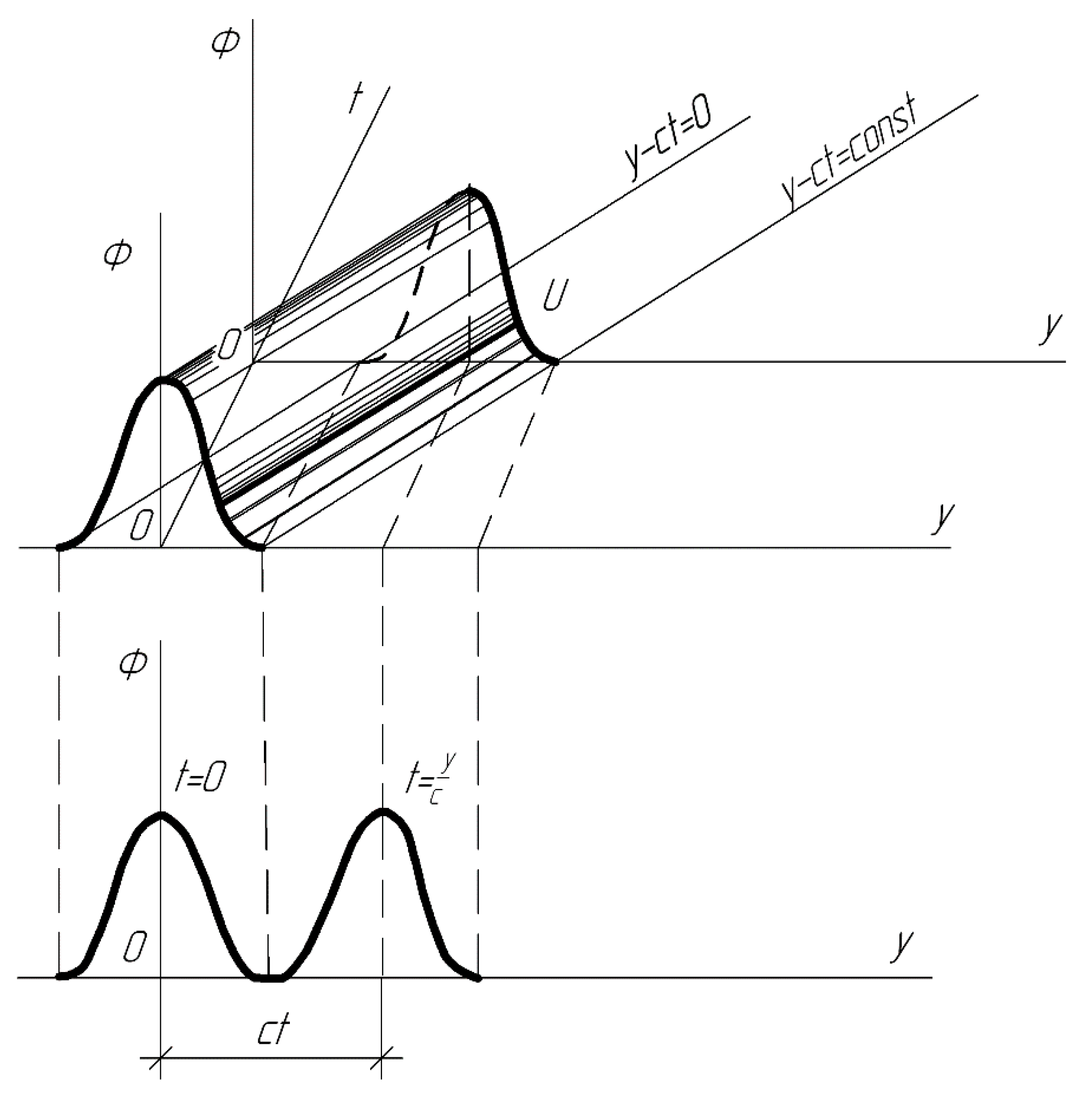
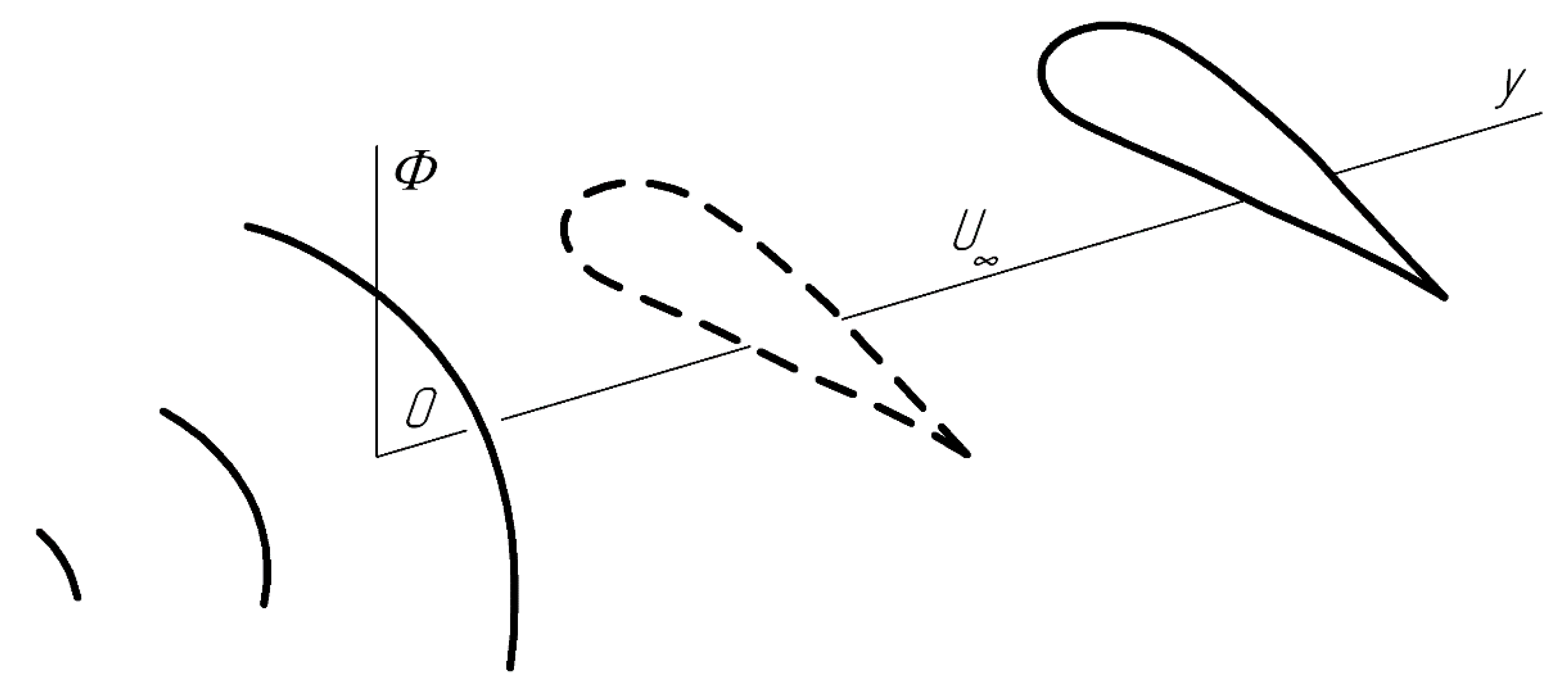
Let us assume that in the liquid surrounding a submersible vehicle, a nonstationary acoustic wave with potential is propagated (
Figure 4).
Let us accept that the submarine’s hull has two mutually perpendicular planes—transversal ones and the plane of frame. In the initial instant of time, the planes are perpendicular to the front of the acting wave.
In the future, this simplification will allow for avoiding cumbersome calculations. Along with this, it is worth noting that the problem can also be solved for the case of arbitrary orientation of the symmetry planes of the submarine and the incident wave’s front.
Movements of the submarine’s hull due to the excessive or negative buoyancy will be neglected for simplicity’s sake.
Concerning the function of the potential of velocity
the following idea will be advanced. On
,
tends towards a particular boundary. The latter will be interpreted so that the total impulse of the pressure wave is as follows:
over the whole period of
, and the action is considered to be limited.
The function
has an unmeasurable configuration and moves along the positive direction of the axis
with velocity “c” (
Figure 4). In the phase plane
the function
maintains a constant value on the lines
. The surface
is cylindrical and its generatrices are parallel to the line
. The guide of the surface
is curved on
, i.e.,
Let us prove that, based on the accepted assumptions concerning the properties of the acting acoustic pressure wave, movements of the hull of the submarine (in the mode of “stop the engine”) will approach some boundary upon . Let us also calculate its value.
The problem is solved in the acoustic approximation.
Change in the amount of motion over the time
equals a complete force of impulse over this time. The force
acting on the submarine’s hull is equal to a partial time derivative of potential, i.e.,
The vector field is the potential if it is a gradient of some scalar field, in other words:
The scalar field is called the potential of the field
. The “minus” sign before
has been chosen for the convenience of further calculations. According to the considered problem, it means that in the direction of the vector
the elementary impulse of force:
is descending.
So, based on the assumption of the symmetry of the hull and on the absence of its own motion, the submarine will move towards the acting pressure wave, i.e., towards the axis .
The differential equation of the submarine’s motion within the mentioned simplifications can be written as follows:
where
—forced motion of submarine owing to the action of acoustic wave;
—vehicle’s weight;
—density of the medium;
—direction of the external normal to the surface
of external (pressure) hull of submarine;
—cross-section contour in the plane of frame;
—angle cosine between the external normal and axis
; the integrations are performed along the whole surface
;
—potential of diffraction wave, which is subordinated to the three-dimensional wave Laplace’s equation:
and to the initial conditions:
If
then the function is
, and the following condition takes place on the hull’s surface:
The following ratios take place in the cylindrical coordinates:
Having twice integrated Equation (8) within the limits from zero to
, we obtain
where
The movement of particles of the liquid surrounding the submarine is expressed through these two functions by the formulas:
where
—movement generated by the incident acoustic wave on the condition of absence of the submarine in water;
—additional motion, which is conditioned by the diffraction of acoustic waves.
The incident acoustic wave is propagated in the direction of
, therefore:
The function
is subordinated to the equation:
and to the boundary conditions on the hull’s surface of submarine:
The expressions (16) and (17) are obtained after the integration in time of Equations (9) and (11), taking into account the conditions of (10).
From the very beginning, it was specified that the impulse of pressure wave is limited in time, naturally, so we will consider that the movement of the submarine’s hull
will also be finite as per the value when directing upon
to a certain value:
The potential of incident wave
and, naturally, its integral
have no peculiarities inside the area occupied by the hull of the submarine. On this basis we can write:
With respect of the second integral in the expression (12), and according to (17), it can be represented in the form of:
So, the transformations (19), (20) will allow for expression (12) and change in the following fashion:
In order to, finally, calculate the movements of the submarine affected by the acoustic wave one has to know the function
, and this, under a generalized statement, is not possible. So, it makes sense not to seek the value
, but rather, the final object’s displacement, in other words:
Simultaneously, this threshold value may not exist. Thus, if the acoustic wave had the form of jump, in the result of its action, the unfixed hull would obtain some constant velocity. Yet if a full impulse of pressure is limited, the particles of water will obtain limited movement and, naturally, to expect that the final one, by value, will be the movement of the submarine.
Let us assume that this is fulfilled. Let us analyze to what such an opinion will lead.
Let us consider
,
. Then, from Equation (21) we obtain:
where
is the mass displaced by the submarine water.
Thus, one has to find:
where:
As has been noted, the function
is subordinated to the right part of Equation (16), which tends towards zero on
, because it is proportional to the pressure in the diffraction wave. So
will be a harmonious function. It is based on
, and on the surface of the submarine’s hull meeting the following conditions:
Hence it appears that may be identified with the boundless ideal liquid when the examined underwater object is moving in it with a constant velocity A towards the axis . Note that within the interests of the assigned task, we are not interested in the function itself but in the integral (24) only.
Let us transform it according to the formula of J. Green, on the condition that at
the function
tends towards zero as
. So,
Thus, the problem comes to finding the integral:
But this is nothing other than the kinetic energy of the ideal incompressible liquid in the problem with the boundary conditions (26). Therefore, it can be written:
where
—is the added mass coefficient for the cylinder moving towards the axis
.
Taking into account the expressions (26) … (29), Formula (22) takes on the form:
Having solved this equation relative to
, we obtain the value of the forced movement of the submarine (
Figure 5):
Thus, the assumption of the existence of the submarine’s finite motion (22) turns out to be justified, since it does not contradict expression (31).
The analyzed case of the forced motion of the submersible vehicle can be broadened and the underwater object can be considered as a random geometric shape. In this case, unlike the already considered one, we will still observe the rotational motion with respect to all three axes. For the six unknowns, we create a linear algebraic system, coefficients of which will depend on 21 added-mass coefficients and static moments of masses.
For the purpose of a more profound understanding of the assigned task’s gist, all subsequent reasoning is based on a particular technical solution—the submarine is affected by acoustic shock, and the motion of the submersible vehicle is absent.
Let the external pressure hull of the submarine with weight M be an absolutely solid body which is in real, for simplification, incompressible liquid and below the periscope depth. The motion of submarine is absent.
Functions determining the displacement of the medium and its interaction with the submarine’s hull have the form:
where
—attached mass (
);
—friction coefficient;
is the Heaviside unit function (equal to zero for negative values in the argument and one for positive);
—delta function of Dirac (the time argument is t and has dimension
), which represents the instantaneous value of the perturbing factor’s pulse and possesses the following properties:
or
where:
where
is the Heaviside unit function. Relation between the functions of Dirac and Heaviside is determined by the dependence:
The following equations take place:
The given relations allow for figuring out the regularity of the submarine’s motion from Equation (1). So, when considering only the friction of the hull against the medium with the submarine’s motion, the differential equation of motion has the form:
By applying the Laplace transformation, upon the zero initial conditions, we obtain:
Let us represent the first fraction in the form of the following:
This expression allows for determining the coefficients A, B, C:
Taking into account the found solutions, we have:
Specify:
and transfer to the original:
If the multipliers
and
expand into a series
then:
In this case, the first and second square brackets can be written in another way:
Thus, the solution of the initial differential equation will have the form:
This result coincides with the formula obtained by V.V. Novozhilov [
23].
From what we obtained, it follows that upon sufficiently minor friction of the hull against the medium, as well as upon a sufficiently large value of the time of motion T
, the movement of the submersible vehicle will be described to the fullest extent by the first summand of this formula, i.e.,
The obtained result is explained by the fact that upon the singular displacement:
for the generalized force
in real liquid, the following equality takes place:
With the passage of the time , the motion of the submarine will decrease, upon the condition that , or vice versa, will increase, if .
The problem can be broadened by limiting the submarine’s state with an anchor.
The obtained equations allow for a more thorough analysis of the disturbed movement of the submarine during deep-sea bombing and can be performed for a specific type of submarine.
4. Results and Observations
The technological risks of the submarine in a combat situation are of interest from the point of view of the stability of the underwater vehicle when the submarine is in use. When the frequency of oscillations surround the boat, the environment will commensurate with the natural frequency of the submarine, such as on elastic anchor extensions of the stern and bow. In this case, the generation of amplitude modulation of the angular movement of the submarine is possible. We are talking about the emergence of a regime where the submarine will make a complex movement in the form of two oscillatory movements—the main oscillation frequency, which is also the amplitude modulation, and another, but with more extended space. The appearance of such a situation is the threshold of frequency resonance. The oscillatory movement of the submarine will take place with the presence of a systematic component developing in time, i.e., there will be diverging vibrations of the submarine. The danger of this mode is that if the submarine already has damage to the hull, then this can lead to an irreversible accident. If the danger of the accident is small, then there are certain difficulties in managing the submarine. This is especially in the case of strong energy disturbances in the aquatic environment, such as an assault situation or intensive bombing from the surface of the water and from the air. Violation of the anchor fastener may even be expected, followed by uncontrolled movement of the submarine.
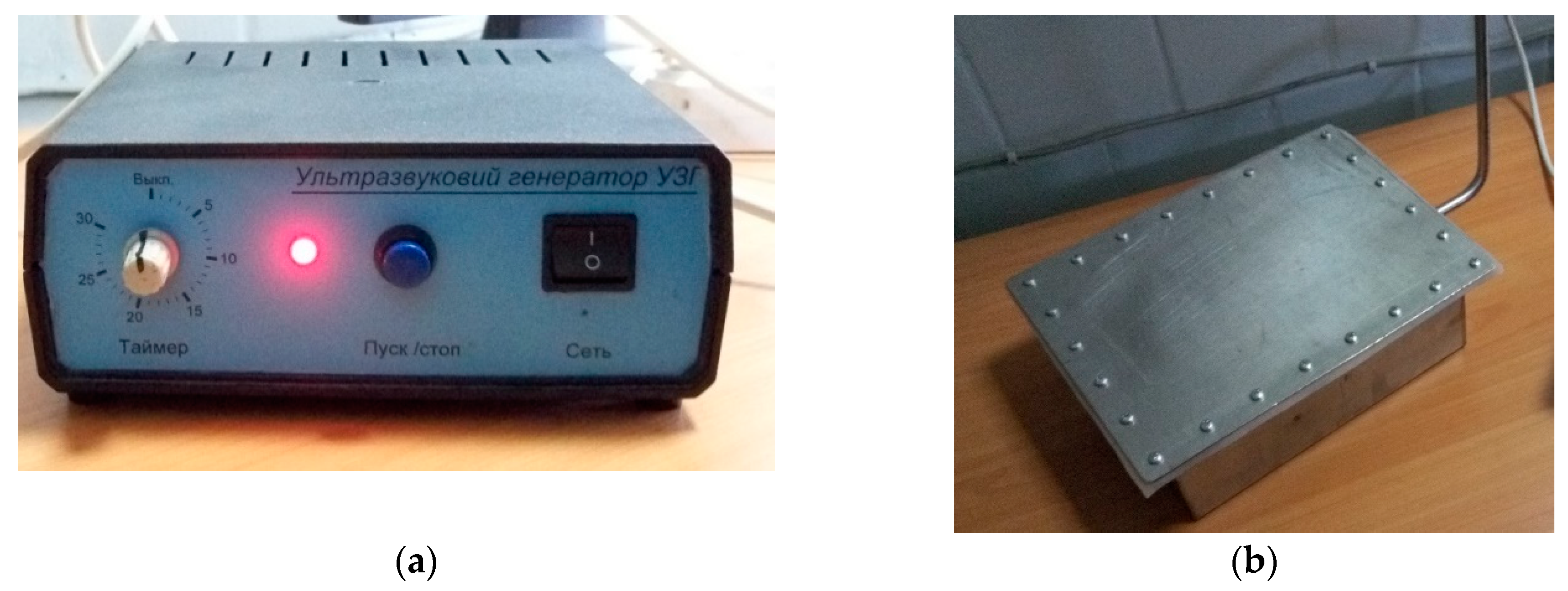
Laboratory studies were performed in the pool of a mass-sized equivalent of a submarine. Studies have been carried out of the analysis of the translational movement of the body under acoustic exposure. As a disturbance factor, an ultrasonic transducer UZP-6-1 was used (
Figure 6a). An ultrasonic emitter was used to create an ultrasound beam with a frequency of 42 kHz and a flat front of a pressure wave, with a power of 300 W and a frequency of ultrasonic vibrations of 1.65 W/cm
3 (
Figure 6b).
Laboratory studies of the effect of the forced disturbed displacement of a submarine model under the influence of acoustic shock have been performed. The influence of the level of acoustic loading on the value of the translational movement of the hull of the submarine to a complete stop is investigated.
To study the elastic properties of the medium by the size and nature of the forced movement of the laboratory model, multicore rubber bands were used. Stranded rubber harnesses were connected to the body and walls of the pool. Studies of the field of elastic forces on the nature and magnitude of the displacement of the model were performed.
The outer shell of the experimental model of the submarine was investigated. The model is approximately 10 cm long in the shape of a metal cylindrical shell. Both ends of the model are equipped with frames of a semicircular shape to ensure the rigidity of the structure as a whole. Such a design eliminates the effects of additional oscillations that impede the assessment. The hull model is installed on braces with a high coefficient of energy dissipation. Thin rubber bands in the form of a tourniquet (small diameter, not more than 1.5 cm) made of thin rubber bands were used. The length of the thin rubber bands is about 20 cm. The model under investigation was immersed in liquid (fresh water at room temperature, approximately 20 °C) to a depth of 20 cm. A sound wave from the ultrasonic emitter UZP-6-1 was directed to this structure under water. The front sound wave was perpendicular to the longitudinal axis of the shell. The influence of hydrodynamic pressure was evaluated visually, without taking into account the influence of diffraction phenomena from the frames and thin rubber bands. The submarine model was submerged by a predetermined value and its displacement under the action of an acoustic wave as a function of temperature was determined. A total of 12 experiments were performed to determine the reliability of the assumptions made. The movement of the body under the action of a sound wave practically did not differ from each other and occurred within 3 seconds at a distance of 15 cm (
Table 1).
To continue the study, it is planned to improve the experimental setup. Studies of temperature heterogeneity in depth, as well as the presence of laminar and turbulent movement of a liquid medium are planned.
Analysis of the obtained results proves the correctness of the assumption that, upon the action of acoustic shock, the elastic deformations of the surface of the external hull of the submarine will not affect the value of the final motion of the submersible vehicle in general, since the values are limited and the residual deformations disappear. In other words, they are equal to zero, and the result of the members corresponding to them are also equal to zero.
In this case, when the functions are not integrable, for example, for the case of real liquid, the weight of the object and deformations of its surface do not influence on the hull’s motion limit.
In the case when deformations of both bodies are elastic and the main central axes as well as their weights (moments of inertia) correspondingly coincide, the final motion of the submarine and the “fictitious” body (medium upon the absence of the submersible vehicle) are equal to each other. The deformations of the “fictitious” body will be elastic, for example, upon the effect of a plane wave, when all of the medium’s particles move to the same distance.
In the case of positive buoyancy, when , the final motion of the vehicle in the medium will exceed the motion of the ideal liquid’s particles. Upon negative buoyancy, there will be less motion of the ideal liquid’s particles. It has been established that in real liquid the weight of the body does not have an effect on the final motion’s value of the submersible vehicle.
The putative contradiction of this assertion is explained by the fact that, when , even slowly, i.e., upon an insignificant friction of hull against the medium, then the body of the positive buoyancy, being more than the liquid of motion, will turn back so that its motion will be equal to the motion of the particles of the liquid. The same situation occurs for the body of negative buoyancy as well.
Based on the obtained research results, it becomes possible to conduct further research:
- -
the study of the unmasking factors of the submarine in full-scale conditions, especially in conditions of asymmetric military operations;
- -
the effect of salinity of sea water and temperature jump;
- -
the formation of a “blende”, which allows for disorienting the means of detection and directing the enemy along a false trail;
- -
study of the influence of the underwater sound channel;
- -
the influence of the N-wave on the dynamic properties of the submarine.
Considering the differential equation of motion of a submarine:
the law of forced, perturbed motion of the submarine (32), assuming its rectilinear motion, under the action of the sound wave
P and in the absence of damping of the medium, will perform rectilinear undamped oscillations about the
X axis with an angular frequency
and amplitude
for an arbitrarily long time. Then, at
, the amplitude of the oscillations will be
.
If we take into account the viscosity of the liquid, then there will be an energy dissipation and, the submarine, under the influence of a sound wave, will translate along the X axis with a frequency and with an amplitude decreasing with time t, that is . The law of translational motion of the submarine will already take the form of decaying in time of oscillations with angular frequency and amplitude , .
Therefore, the amplitude of the oscillations will decrease exponentially with frequency . After making a certain number of oscillations, the submarine is stopped at .
If the damping of the liquid is weak, then the boat will oscillate with a frequency and with an amplitude that decreases rather slowly. As a result, allowing for enough time, the boat will reach the pool wall and stop.
If the damping value, or any other factors, for example, a temperature gradient, salinity, kinematic disturbances, or other factors affecting the state of the medium, significantly lead to an increase in the damping value of the medium, then the submarine, having made a limited number of oscillations, will stop motionless, not reaching the walls of the pool at a distance in the position , where is the final time.
With a significant viscosity of the medium, for example, in the case of violation, the submarine will only translate to its ultimate stop, and without the presence of an oscillating component.


