A Semi-Analytical Load Distribution Model for Cycloid Drives with Tooth Profile and Longitudinal Modifications


Abstract
Featured Application
Abstract
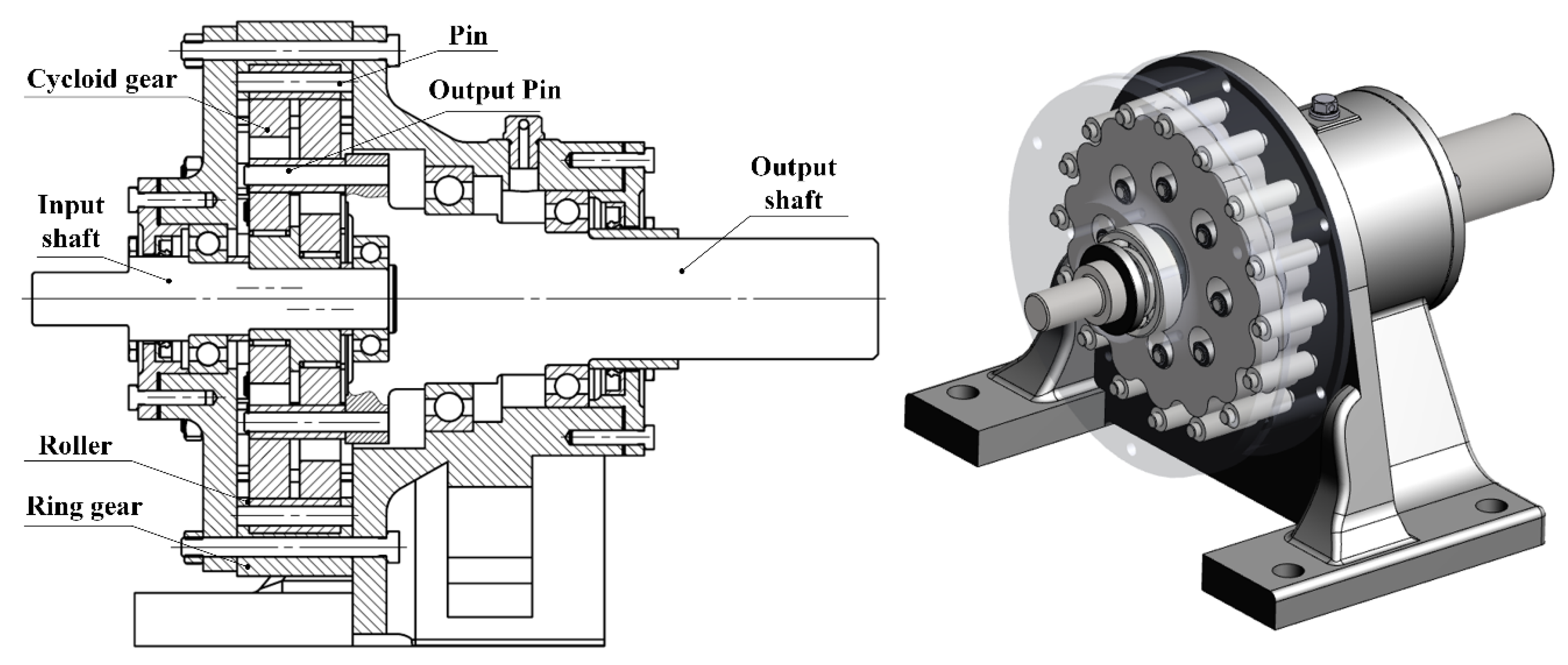
1. Introduction
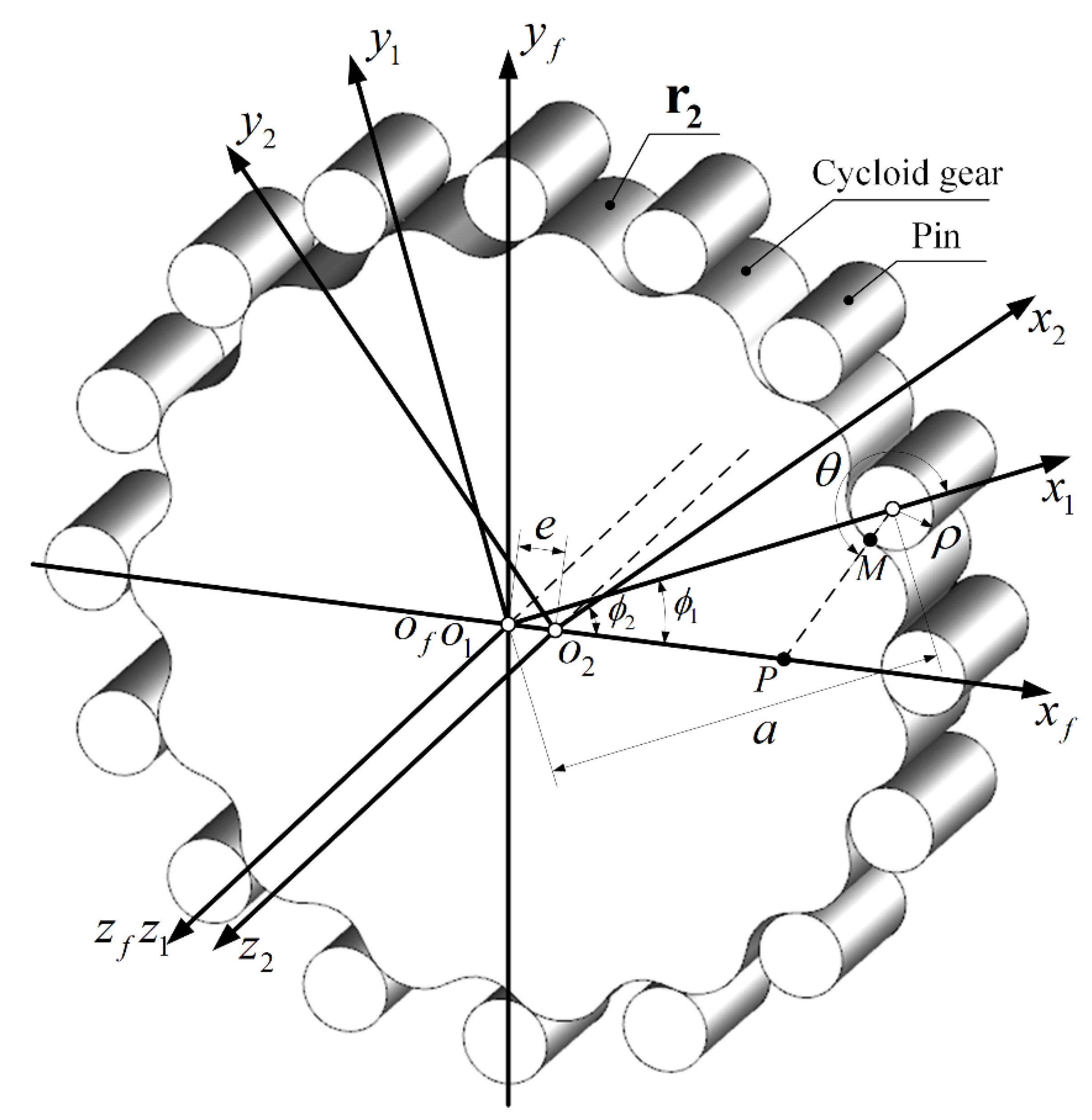
2. Cycloid Gear Tooth Surface Geometry
2.1. Tooth Surface Generation
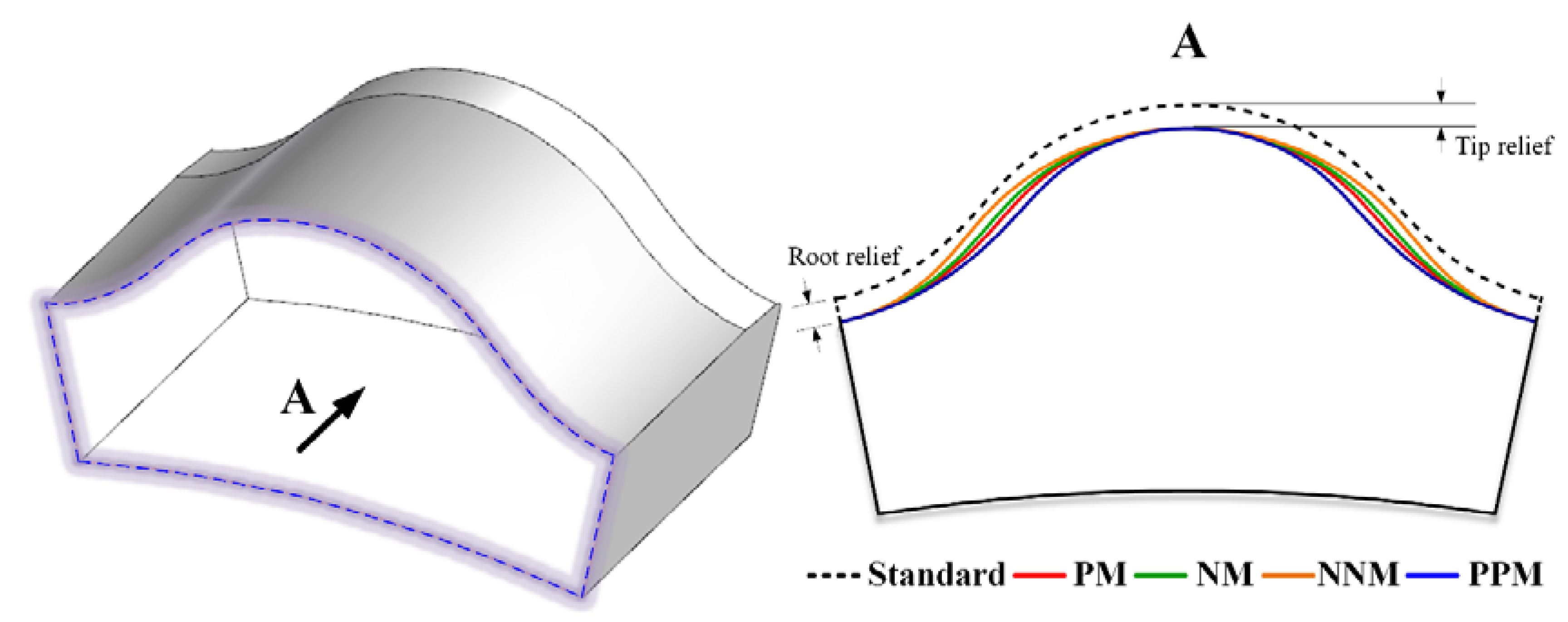
2.2. Tooth Profile Modification
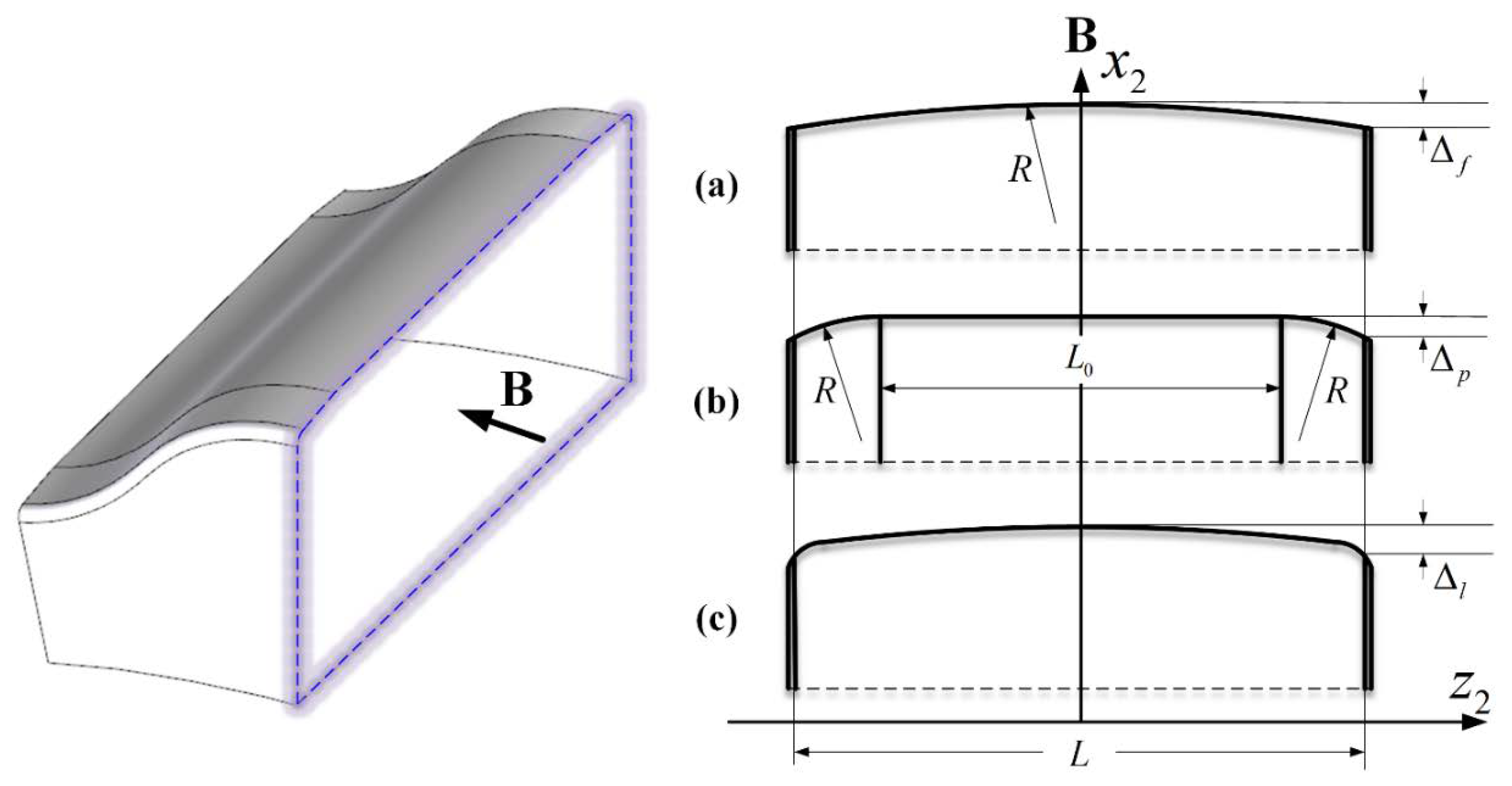
2.3. Tooth Longitudinal Modification
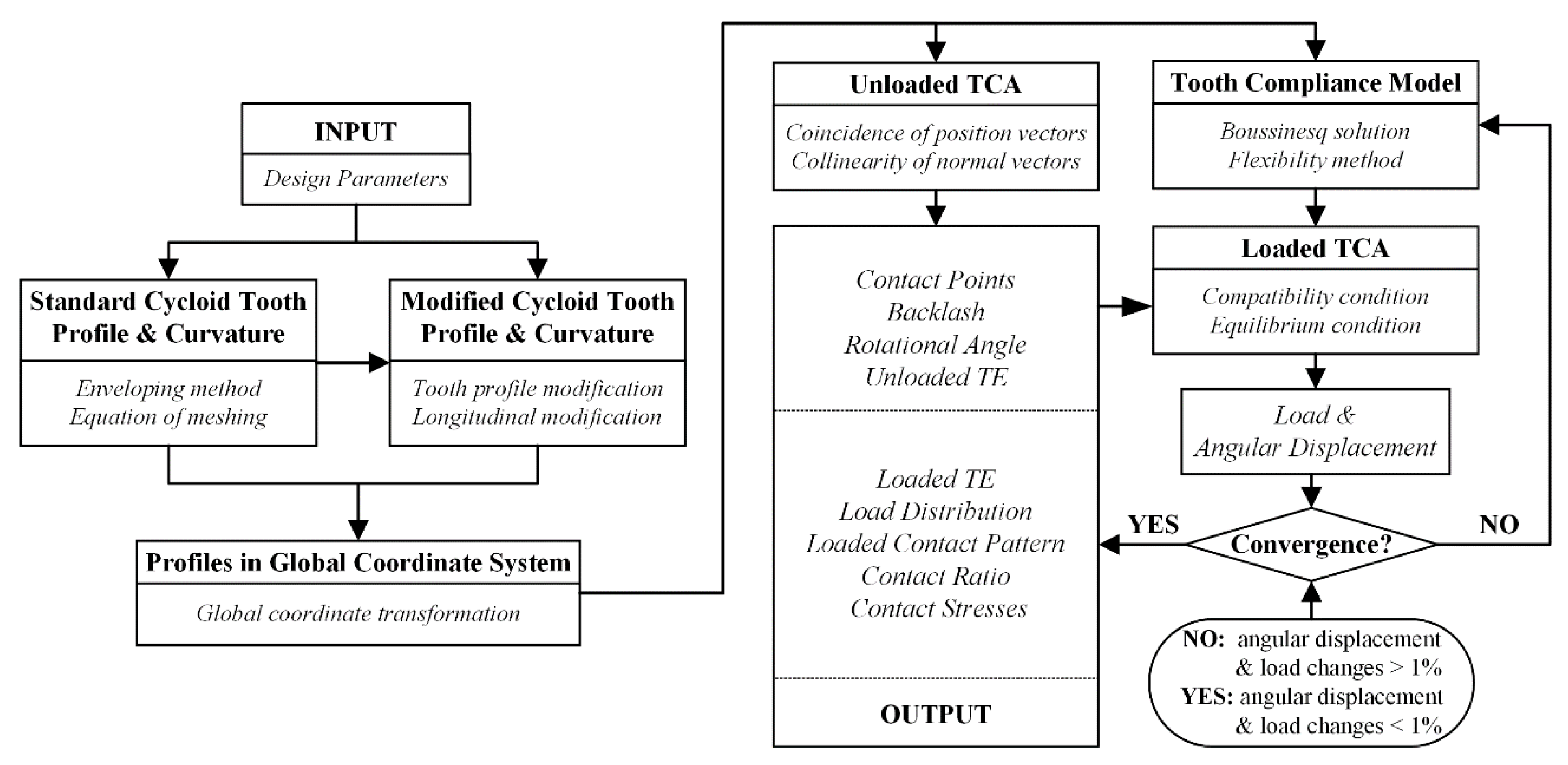
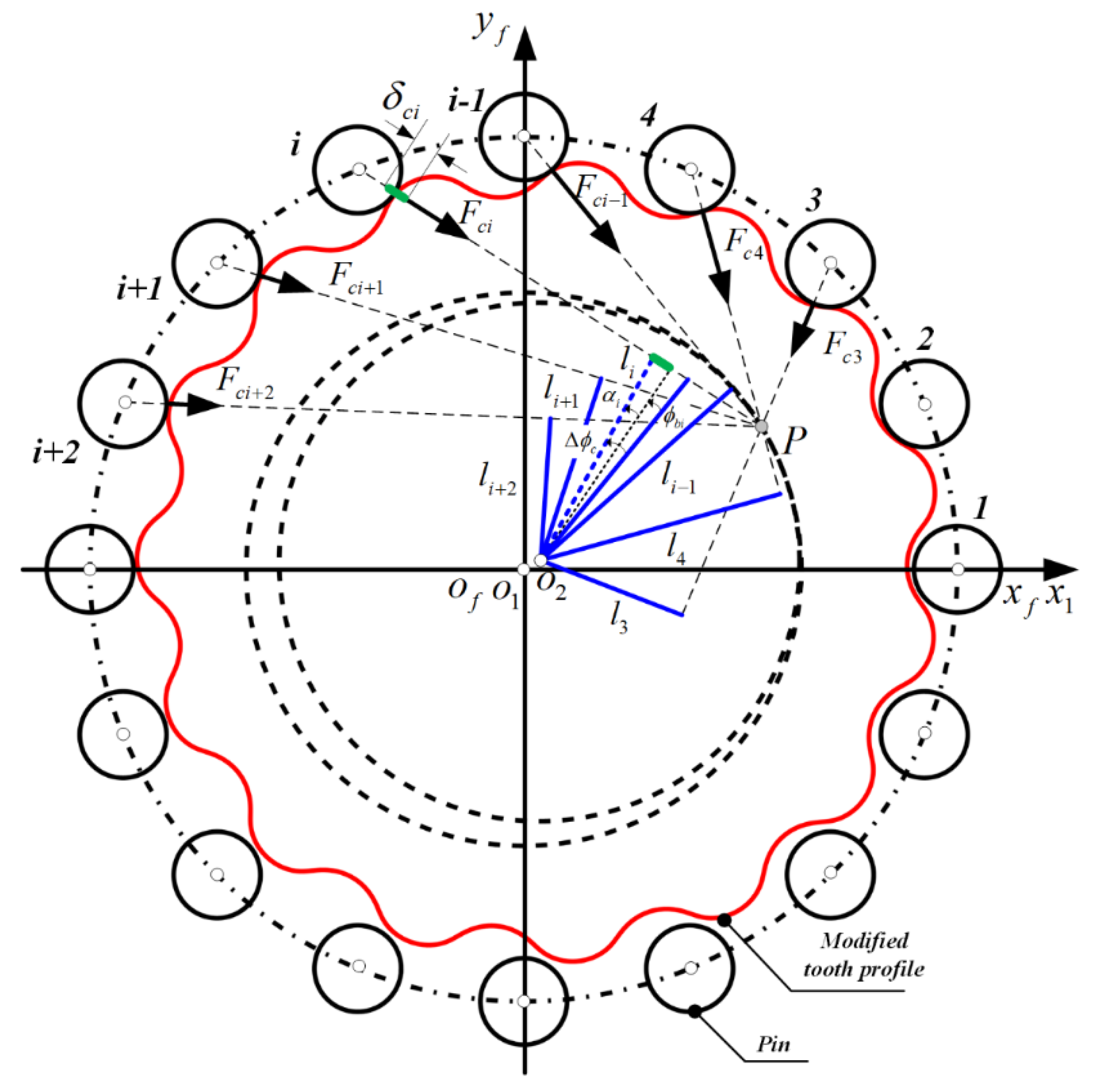
3. Load Distribution Model
- The load distributed on one tooth pair does not affect elastic deformations on adjacent tooth pairs.
- The rotational speed and inertia forces of moving elements are neglected in the quasi-static process.
- The curvature of the gear tooth surface over the contact region is assumed to remain unchanged.
- The friction between contacting tooth pairs is neglected.
3.1. Unloaded Tooth Contact Analysis
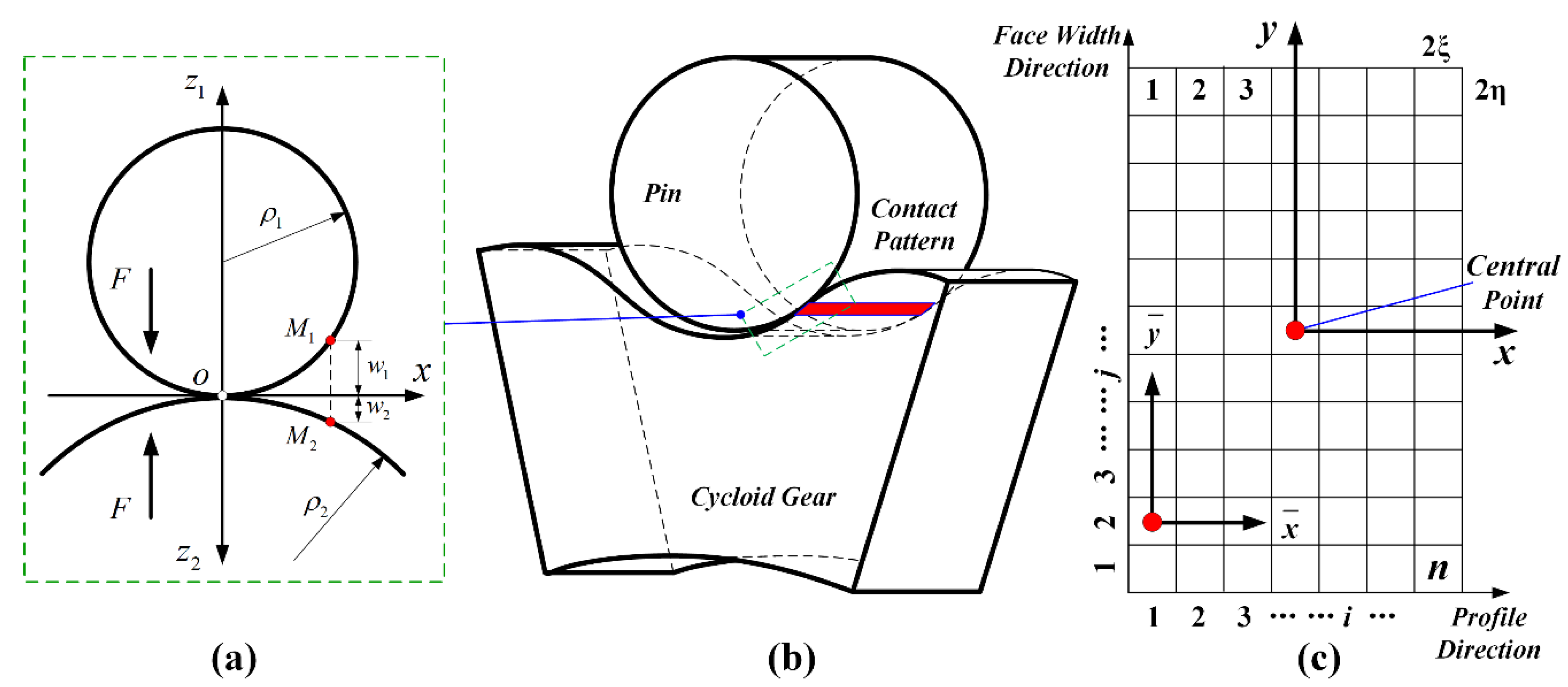
3.2. Tooth Compliance Model
3.3. Loaded Tooth Contact Analysis
4. Numerical Example and Verification
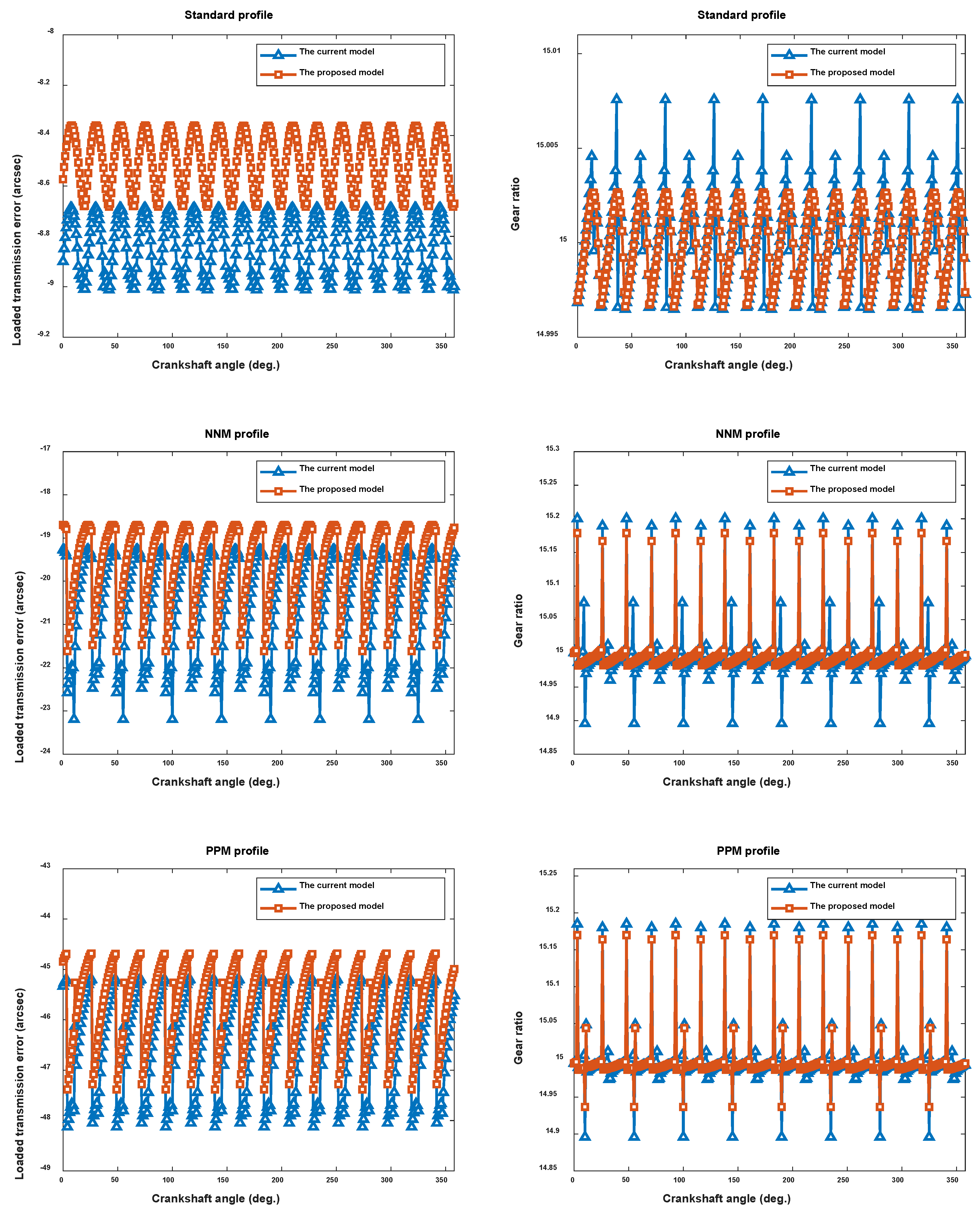
4.1. Verification of the Proposed Model
4.2. Effect of Tooth Longitudinal Modifications
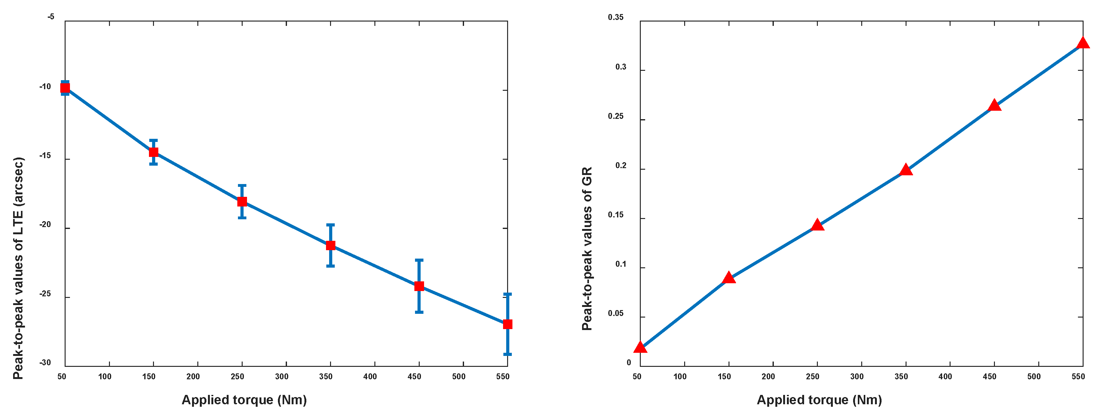
4.3. Effect of Applied Torque Levels
5. Conclusions
Author Contributions
Funding
Conflicts of Interest
References
- Hsieh, C.F.; Fuentes-Aznar, A. Performance prediction method of cycloidal speed reducers. J. Braz. Soc. Mech. Sci. Eng. 2019, 41, 186. [Google Scholar] [CrossRef]
- Hsieh, C.F. Dynamics analysis of cycloidal speed reducers with pinwheel and nonpinwheel designs. J. Mech. Des. 2014, 136, 091008. [Google Scholar] [CrossRef]
- Kumar, N.; Kosse, V.; Oloyede, A. A new method to estimate effective elastic torsional compliance of single-stage cycloidal drives. Mech. Mach. Theory 2016, 105, 185–198. [Google Scholar] [CrossRef]
- Li, S. Design and strength analysis methods of the trochoidal gear reducers. Mech. Mach. Theory 2014, 81, 140–154. [Google Scholar] [CrossRef]
- Li, X.; Chen, B.K.; Wang, Y.W.; Lin, T.C. Mesh stiffness calculation of cycloid-pin gear pair with tooth profile modification and eccentricity error. J. Cent. South Univ. 2018, 25, 1717–1731. [Google Scholar] [CrossRef]
- Malhotra, S.K.; Parameswaran, M.A. Analysis of a cycloid speed reducer. Mech. Mach. Theory 1983, 18, 491–499. [Google Scholar] [CrossRef]
- Blagojevic, M.; Marjanovic, N.; Djordjevic, Z.; Stojanovic, B.; Disic, A. A new design of a two-stage cycloidal speed reducer. J. Mech. Des. 2011, 133, 085001. [Google Scholar] [CrossRef]
- Gorla, C.; Davoli, P.; Rosa, F.; Longoni, C.; Chiozzi, F.; Samarani, A. Theoretical and experimental analysis of a cycloidal speed reducer. J. Mech. Des. 2008, 130, 112604. [Google Scholar] [CrossRef]
- Wang, H.; Shi, Z.Y.; Yu, B.; Xu, H. Transmission performance analysis of RV reducers influenced by profile modification and load. Appl. Sci. 2019, 9, 4099. [Google Scholar] [CrossRef]
- Xu, L.X.; Chen, B.K.; Li, C.Y. Dynamic modelling and contact analysis of bearing-cycloid-pinwheel transmission mechanisms used in joint rotate vector reducers. Mech. Mach. Theory 2019, 137, 432–458. [Google Scholar] [CrossRef]
- Xu, L.X.; Yang, Y.H. Dynamic modeling and contact analysis of a cycloid-pin gear mechanism with a turning arm cylindrical roller bearing. Mech. Mach. Theory 2016, 104, 327–349. [Google Scholar] [CrossRef]
- Sun, X.; Han, L.; Wang, J. Design and transmission error analysis of CBR reducer. J. Mech. Des. 2019, 141, 082301. [Google Scholar] [CrossRef]
- Li, T.; An, X.; Deng, X.; Li, J.; Li, Y. A new tooth profile modification method of cycloidal gears in precision reducers for robots. Appl. Sci. 2020, 10, 1266. [Google Scholar] [CrossRef]
- Li, T.; Tian, M.; Xu, H.; Deng, X.; Su, J. Meshing contact analysis of cycloidal-pin gear in RV reducer considering the influence of manufacturing error. J. Braz. Soc. Mech. Sci. Eng. 2020, 42, 1–14. [Google Scholar] [CrossRef]
- Li, X.; Li, C.Y.; Wang, Y.W.; Chen, B.K.; Lim, T.C. Analysis of a Cycloid Speed Reducer Considering Tooth Profile Modification and Clearance-Fit Output Mechanism. J. Mech. Des. 2017, 139, 033303. [Google Scholar] [CrossRef]
- Sensinger, J.W. Unified approach to cycloid drive profile, stress, and efficiency optimization. J. Mech. Des. 2010, 132, 024503. [Google Scholar] [CrossRef]
- Lin, W.S.; Shih, Y.P.; Lee, J.J. Design of a two-stage cycloidal gear reducer with tooth modifications. Mech. Mach. Theory 2014, 79, 184–197. [Google Scholar] [CrossRef]
- Lin, K.-S.; Chan, K.-Y.; Lee, J.-J. Kinematic error analysis and tolerance allocation of cycloidal gear reducers. Mech. Mach. Theory 2018, 124, 73–91. [Google Scholar] [CrossRef]
- Chen, B.; Zhong, H.; Liu, J.; Li, C.; Fang, T. Generation and investigation of a new cycloid drive with double contact. Mech. Mach. Theory 2012, 49, 270–283. [Google Scholar] [CrossRef]
- Chen, B.; Fang, T.; Li, C.; Wang, S. Gear geometry of cycloid drives. Sci. China Ser. E Technol. Sci. 2008, 51, 598–610. [Google Scholar] [CrossRef]
- Shin, J.H.; Kwon, S.M. On the lobe profile design in a cycloid reducer using instant velocity center. Mech. Mach. Theory 2006, 41, 596–616. [Google Scholar] [CrossRef]
- Dion, J.L.; Pawelski, Z.; Chianca, V.; Zdziennicki, Z.; Peyret, N.; Uszpolewicz, G.; Ormezowski, J.; Mitukiewicz, G.; Lelasseux, X. Theoretical and experimental study for an improved cycloid drive model. J. Appl. Mech. 2019, 87, 011002. [Google Scholar] [CrossRef]
- Litvin, F.L.; Fuentes, A. Gear Geometry and Applied Theory; Cambridge University Press: Cambridge, UK, 2004. [Google Scholar]
- Tran, T.L.; Pham, A.D.; Ahn, H.J. Lost motion analysis of one stage cycloid reducer considering tolerances. Int. J. Precis. Eng. Manuf. 2016, 17, 1009–1016. [Google Scholar] [CrossRef]
- Chang, L.C.; Tsai, S.J.; Huang, C.H. A study on tooth profile modification of cycloid planetary gear drives with tooth number difference of two. Forsch. Ing. 2019, 83, 409–424. [Google Scholar] [CrossRef]
- Jia, C.; Fang, Z.; Zhang, Y. Topography of modified surfaces based on compensated conjugation for the minimization of transmission errors of cylindrical gears. Mech. Mach. Theory 2017, 116, 145–161. [Google Scholar] [CrossRef]
- Simon, V. Optimal tooth modifications for spur and helical gears. J. Mech. Trans. Autom. 1989, 111, 611–615. [Google Scholar] [CrossRef]
- Tran, V.T.; Hsu, R.H.; Tsay, C.B. Study on the anti-twist helical gear tooth flank with longitudinal tooth crowning. J. Mech. Des. 2014, 136, 061007. [Google Scholar] [CrossRef]
- Hong, J.; Talbot, D.; Kahraman, A. A semi-analytical load distribution model for side-fit involute splines. Mech. Mach. Theory 2014, 76, 39–55. [Google Scholar] [CrossRef]
- Kolivand, M.; Kahraman, A. A load distribution model for hypoid gears using ease-off topography and shell theory. Mech. Mach. Theory 2009, 44, 1848–1865. [Google Scholar] [CrossRef]
- Tong, V.C.; Hong, S.W. Characteristics of tapered roller bearings in relation to roller profiles. J. Mech. Sci. Technol. 2015, 29, 2913–2919. [Google Scholar] [CrossRef]


| Profile Modification | Relationship | ||
|---|---|---|---|
| PM (positive roller radius modification) | 0 | Positive | - |
| NM (negative roller position modification) | Negative | 0 | - |
| NNM (negative roller position and negative roller radius modification) | Negative | Negative | |
| PPM (positive roller position and positive roller radius modification) | Positive | Positive |
| Parameter | Description | Value |
|---|---|---|
| Cycloid gear tooth number | 15 | |
| Roller number | 16 | |
| Roller position | 90 mm | |
| Roller radius | 7.2 mm | |
| Eccentricity | 4.5 mm | |
| Width of cycloid gear | 17 mm |
| Standard | NNM | PPM |
|---|---|---|
| μm | μm | μm |
| μm | μm | μm |
| Without TLM | FCM | PCM | LCM |
|---|---|---|---|
| - | mm | mm, mm |
© 2020 by the authors. Licensee MDPI, Basel, Switzerland. This article is an open access article distributed under the terms and conditions of the Creative Commons Attribution (CC BY) license (http://creativecommons.org/licenses/by/4.0/).
Share and Cite
Zhang, T.; Li, X.; Wang, Y.; Sun, L. A Semi-Analytical Load Distribution Model for Cycloid Drives with Tooth Profile and Longitudinal Modifications. Appl. Sci. 2020, 10, 4859. https://doi.org/10.3390/app10144859
Zhang T, Li X, Wang Y, Sun L. A Semi-Analytical Load Distribution Model for Cycloid Drives with Tooth Profile and Longitudinal Modifications. Applied Sciences. 2020; 10(14):4859. https://doi.org/10.3390/app10144859
Chicago/Turabian StyleZhang, Ting, Xuan Li, Yawen Wang, and Lining Sun. 2020. "A Semi-Analytical Load Distribution Model for Cycloid Drives with Tooth Profile and Longitudinal Modifications" Applied Sciences 10, no. 14: 4859. https://doi.org/10.3390/app10144859
APA StyleZhang, T., Li, X., Wang, Y., & Sun, L. (2020). A Semi-Analytical Load Distribution Model for Cycloid Drives with Tooth Profile and Longitudinal Modifications. Applied Sciences, 10(14), 4859. https://doi.org/10.3390/app10144859